
Turboexpander repair and maintenance for sustained performance and profitability
Turboexpanders are critical equipment for many applications including gas processing, industrial gas, power recovery and power generation, and their longevity and sustained performance is often key to the profitability of a business. This article provides an overview of the major elements involved in the work of maintaining turboexpanders. The discussion traces issues related to the design and field operation of the machine, as well as shop repairs. Users will find valuable insights and suggestions made by practitioners with an original equipment manufacturer (OEM) and aftermarket perspective.
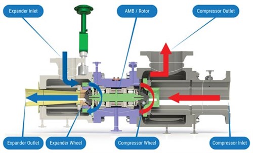
What is a turboexpander? A turboexpander is a rotating machine equipped with a radial inflow expansion turbine and a loading or breaking device, such as a centrifugal compressor stage, a generator or an oil brake. Unlike a power generation or mechanical drive turbine, which works mainly to generate power, an expander’s main purpose is to increase the efficiency of a gas expansion process. FIG. 1 provides a schematic of a typical turboexpander operating in a gas liquification process.1
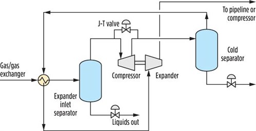 |
| FIG. 1. Typical natural gas liquefaction process. |
Where are turboexpanders used? More than 5,000 turboexpander units are in operation across the globe in a variety of applications. The equipment is standard in the natural gas industry for liquification and dewpoint control, and it is also commonly employed in the petrochemical industry for ethylene plants, air separation and refrigeration.1
In all of these processes, there is a need to change the state of a gas to a given pressure and temperature. For example, a refrigeration cycle requires that the gas be greatly expanded to reduce its temperature. This is referred to as a Joule–Thompson (J–T) effect, which can be accomplished with a throttling valve (gate or otherwise) that achieves a constant enthalpy expansion adiabatically, with no work output.
Turboexpanders can accomplish the same sharp pressure drop more efficiently because the turbine extracts additional work from the gas expansion due to the mechanical motion. In cases in which the loading device is a compressor stage or a generator, the expander provides power recovery.
What are the components of a turboexpander? A typical turboexpander comprises three main sections—namely, the compressor case, the expander case and the mechanical center section (FIG. 2).
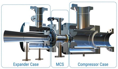 |
| FIG. 2. Turboexpander cross-section. Image courtesy of L.A. Turbine. |
Turboexpander cases are usually radially split and grouped in three distinct parts. The expander casing is usually stainless steel, due to the low-temperature gas it contains. In many designs, it houses the inlet guide assembly. The compressor casing is usually made of carbon steel. It forms the diffuser part of the compressor stage, as well as the collector or volute, depending on the design.
FIG. 3 focuses on the mechanical center section (MCS), which is the heart of the machine. The bearing housing is usually carbon steel and contains almost the entire machine, from the expander wheel to the compressor wheel. It includes the rotor, bearings and seals. The following is an overview of the key components of the MCS and their functions and main design features.
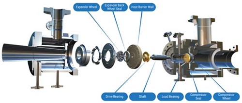 |
| FIG. 3. Mechanical center section detail. Image courtesy of L.A. Turbine. |
Rotor. The rotating element is comprised of a shaft (often made from stainless steel) with a radial inflow turbine wheel attached on one end and the loading device, which in FIG. 3 is a centrifugal compressor wheel, but it could be a generator or a dyno.
Wheels. Wheels are usually computer numerical control (CNC)-milled from a forging, either high-strength aluminum or titanium in some applications. They can be hard anodized or shot peened for additional protection against corrosion.
The wheels can be mounted onto the shaft in a variety of ways, namely, keyed cylindrical or tapered bores, or keyless polygon fits, to name a few. Each wheel can be fastened to the shaft with a high-strength screw bolted onto an internal thread in the shaft. Another common design solution features a hollow shaft with a through-bolt that secures both wheels with end nuts.
The large rotating components are balanced individually first, and later put together as an assembly and balance checked, per the applicable section in API 617. This allows the wheels to be interchanged in the field without having to send the MCS to the shop for a rebalance. However, for some applications, OEMs specify that the rotor be balanced as an assembly and the parts match-marked, in which case the wheels cannot be replaced without a full rotor rebalance.
From a shop inspection perspective, some of the most common findings on wheels include:
- Wear and/or corrosion to the blade surfaces
- Dings to the blades due to foreign object damage (FOD)
- Bent blade tips due to FOD or an error in installation/shipping
- Excessive rubs in the blade tips due to contact with the stationary surface
- Rub damage to the labyrinth teeth of a seal that rides in the back of the wheel, if applicable [this seal is called the expander wheel back seal (see FIG. 3), and it is intended for control of the thrust produced by the expander wheel]
- Cracked blades due to mechanical fatigue.
Findings No. 1 through No. 5 are usually repairable depending on the severity of the damage and the judgement of the repair engineer. For instance, FOD on the blades can be dressed and blended by hand. Aluminum alloy wheels can be hard anodized or shot peened to increase resistance to wear, corrosion or cracking.
In the case of finding No. 5, labyrinth seal rub damage on the wheel can sometimes be recovered by mechanically lifting the seal tip in a lathe and re-machining to reclaim design tolerances. The expander wheel back seals are often coated with a soft metal like babbitt, which is abradable. As part of the repair, it is customary to remove the layer of coating, reapply it and re-machine to design specifications. This allows the wheel to be salvaged without compromising its performance. For any of these repair options, the wheel must be rebalanced per OEM specifications.
Cracked wheels are not uncommon, and a root cause failure analysis must be undertaken. Understanding the root cause will help the repair facility formulate applicable remedial measures, such as coatings or full-blown redesigns or material upgrades. A root cause failure analysis also assists the customer to address process issues, like contamination of the process gas with corrosive elements (e.g., hydrogen sulfide), which might not have been part of the initial design intent of the machine.
FIG. 4 shows an example of finding No. 6 in which replacing the wheel was necessary. Here, an expander wheel blade was cracked during operation. A visual examination shows heavy corrosion damage throughout. A metallographic evaluation shows that the crack likely occurred due to a type of mechanical fatigue that is precipitated by a corrosive element (known as stress corrosion cracking). In such an extreme case, some measures can be taken from a repair or redesign perspective to ameliorate the problem. Ultimately, however, resolution of the contamination problem at the plant process level is inescapable.
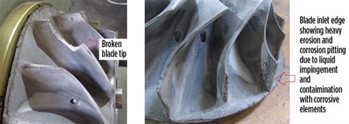 |
| FIG. 4. Wheel with extensive corrosion damage. |
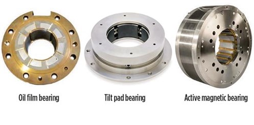
Bearings. These components support the weight of the rotor, as well as overcome the axial force (thrust) originated by the difference in pressures between the front and back of each wheel. Ideally, the thrust in one wheel would be equal and opposite to that of the opposite wheel, but this is rarely the case. In most cases, turboexpanders are equipped with either hydrodynamic oil bearings (FIG. 3) or active magnetic bearings (AMBs) (FIG. 5).
 |
| FIG. 5. Turboexpander equipped with active magnetic bearings. Image courtesy of L.A. Turbine. |
Turboexpanders feature compound radial/thrust bearings on each side of the mechanical center section. Oil bearings are commonly of the fixed-geometry type with babbitted tapered-land journal and thrust surfaces. The oil used is typically ISO VG 32, although ISO VG 64 is not uncommon. The taper in the radial and axial surfaces forms a “wedge” of oil between the stationary and moving surfaces, which generates the necessary vertical lift and axial thrust capacity. The oil wedge also provides the needed damping to attenuate vibrations. Some rotor designs are prone to unstable vibrations, in which case tilting pad bearings are used since they provide rotor dynamic stability.
When a turboexpander is sent to a shop for inspection, it is typical to find moderate to heavy wear on the babbitted areas. The wear can be caused by a number of issues, such as oil contamination and/or degradation, excessive rotor thrust, system upsets, etc. From an aftermarket perspective, the scope of repair involves replacement or reapplication of the babbitt layer, depending on lead time and cost. For older designs, this opens an opportunity to consider various design upgrades that make the bearings more reliable.
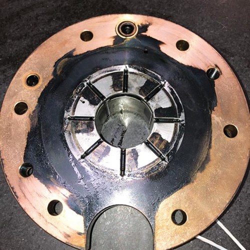
Sometimes a failure analysis is warranted. For example, FIG. 7 shows a case in which oil contamination led to exceedingly high oil operating temperatures evidenced by bearings covered in black residue (upper image). In another instance, a bearing shows damage to the thrust face caused by electrical sparking during operation (lower image).
 |
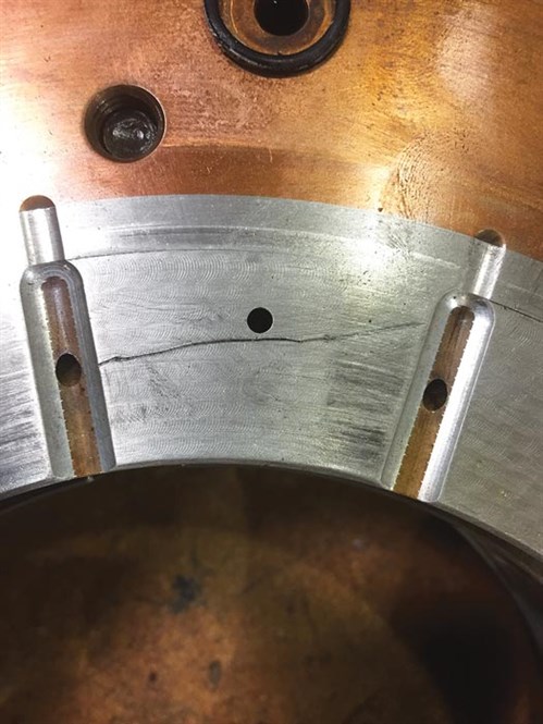 |
| FIG. 7. Oil bearing damage. |
Shafts. Shafts are designed to have some protection in the bearing location with chrome plating, high-velocity oxygen fuel (HVOF) tungsten carbide, or even dry film lubricant. These protective measures provide a barrier between the bearing and the shaft base material. Operational problems with the bearings and the seals often lead to some degree of wear or damage in the shaft. The most common is wear or rub damage in the bearing or seal areas. Many times, shafts can be easily repaired by reapplying the coating.
AMBs are common in the petrochemical industry. These bearings require a high-speed, five-axis controller that maintains the rotor in a stable orbit. From a shop repair perspective, AMBs are typically serviced at the bearing OEM due to their complexity. OEMs will perform a thorough mechanical and electrical evaluation and formulate a scope of work.
Seals. Shaft seals are placed on both sides of the machine and are typically single-port, non-contacting labyrinth seals. The labyrinth teeth can be located on either the stationary portion of the seal or on the rotating shaft. The seal on the expander end is incorporated into the so-called “heat barrier wall” (see FIG. 3 and FIG. 8). The heat barrier wall is manufactured from a glass epoxy laminate that provides mechanical strength, as well as insulation of the bearing cavity from the expander section at very low temperatures.
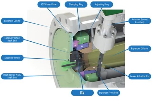 |
| FIG. 8. Variable inlet guide vane assembly. Image courtesy of L.A. Turbine. |
On the compressor side of the machine, the stationary seal element (called a compressor seal, see FIG. 3) can be made of different materials, depending on the application, but an aluminum alloy is common. From a repair perspective, a typical finding is that the seal areas—both on the heat barrier wall and the compressor seal—have experienced some degree of wear due to rubs. Rubs are not uncommon and are related to transient excursions of rotor lateral vibrations, usually during startup. They can be repaired by boring out the damaged section(s), installing a blank insert of a matching material and re-machining the seal features to specification.
Inlet guide vanes (IGVs). The inlet guide vanes are the variable stators of the expander stage. The airfoil-shaped mechanical elements provide an efficient aerodynamic flow path for the expander gas to enter the rotating wheel. They also function like a valve, by closing to pinch the flowrate. OEMs differ widely in their chosen designs for IGVs. Some choose to have four or five vanes with simple adjustment mechanisms. Others opt for a larger number of vanes with complex linkage mechanisms.
Parts inside the IGV are exposed to two wear mechanisms: namely, friction and erosion. The friction stems from repeated sliding motion against contacting parts that are pressurized against each other. Erosion wear is fairly common in the surfaces of the nozzle segments in direct contact with the high-speed part-liquid, part-gas flow; therefore, these parts are often designed with hard coatings, such as HVOF tungsten carbide, to provide a smooth, solid surface for friction protection and a hard surface to slow down erosion. Under normal wear conditions, these components can be repaired by removing and reapplying the coating.
How should turboexpanders be monitored for health? A common question among users is how turboexpanders should be monitored for health. Frequent monitoring of the machine after commissioning and during the first year of operation is critical. Operators should keep a log of important data:
- Process temperatures and pressures in the expander and compressor (if available) streams
- Bearing support system—i.e., lube oil system (if it is an oil-bearing machine)
- Rotor vibrations
- Seal gas filters
- Valves.
Such information is instrumental in providing visibility to mechanical problems or performance deficiencies. Data can be retrieved from the human machine interface (HMI) and/or the distributed control system (DCS), or even written down and kept for future reference. While control systems provide warnings and alarms when the expander operates outside of its design constraints, historical data logs may highlight operational changes not easily observed in the HMI. Operations and maintenance personnel should gather a baseline of how the unit performs to more easily identify unfavorable trends over time, and gauge performance after plant shutdowns or upsets. It is important to remember that process drifts and performance deterioration can occur slowly over a period of years and may go unnoticed as the changes turn into norms.
Another common question is whether turboexpanders have an hourly runtime or a periodic overhaul cycle. The answer is neither, as these machines are designed to run practically indefinitely. A turboexpander can be expected to perform as designed for years without issue as long as some operational conditions are met:
- The process remains largely stable and without upsets
- The seal gas and seal gas filters are kept clean
- The lube oil is regularly tested for contaminants and viscosity
- The lube oil filters are kept in good condition or replaced in a timely fashion
- Contamination in the lube oil system or the process is kept to a minimum.
However, if a condition creates the need to increase the level and frequency of preventative maintenance actions, operators should not hesitate to do so. For example, if a plant’s process has known contaminates that pass to the expander and cause erosion of the wheel blades, then adding inspections, cleaning and possibly performing changeouts of the expander inlet, along with removing and replacing an MCS at regular intervals, may be necessary. Some issues to consider include frequency of system interruptions, a change in the source for process or seal gas, age of equipment, duration of operation since last inspection and particular application (e.g., natural gas processing, air separation, geothermal power generation).
Several major preventative maintenance inspections should be performed:
- Lube oil should be checked every 3 mos–6 mos. Oil sampling should be performed to ensure there is no breakdown in the integrity of the lube oil or presence of contaminants that could affect the performance and efficiency of the turboexpander.
- Routine readings should be documented for operating conditions, processing gases and seal gas to ensure that the turboexpander is operating within engineering design ranges (as previously noted).
- Critical checks include:
a. Seal gas differential pressure
b. Thrust pressure and differential pressure instruments
c. Lube oil differential pressure (oil-bearing systems)
d. Lube oil supply and drain temperatures (oil-bearing systems)
e. Lube oil viscosity (oil-bearing systems)
f. Lube oil filter differential pressure (oil-bearing systems)
g. Reservoir oil level (oil-bearing systems)
h. Auxiliary lube oil pump test (oil-bearing systems) - Replace HMI battery every 2 yr
- Filters should be replaced as they become clogged over time, usually indicated by high differential pressure across the filters.
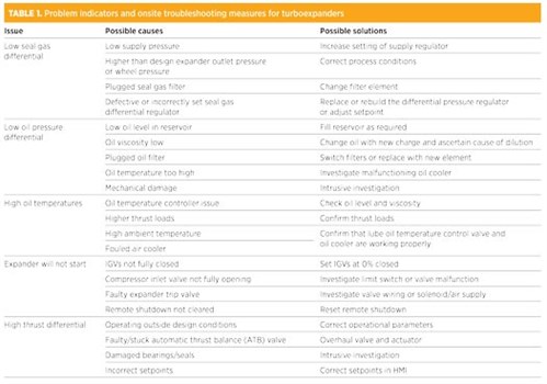
Even following the best preventative maintenance programs, and often as a result of multiple contributing factors, unscheduled maintenance may eventually be required. TABLE 1 summarizes typical problem indicators and onsite troubleshooting measures to be performed.
 |
To provide some perspective, the rotating element may spin from 8,000 rpm to 80,000 rpm, and the gaps (or clearances) with the stationary components (bearings, seals and wheels) are often on the order of just a few thousands of an inch. When an issue or upset causes one part to contact another and is damaged, multiple other parts are also affected and become damaged very quickly.
If a problem leads to a shutdown situation, then users can minimize downtime by having a complete spare MCS and complete spare IGV assembly on hand. Swapping the MCS will typically require a downtime of 3 d–5 d, whereas ordering emergency spare parts can take up to several weeks to manufacture and deliver. It is preferable to refrain from swapping out individual MCS or IGV spare parts in the field unless the work can be performed by a qualified technician with proper experience with these machines. Multiple critical clearances, torques, assembly techniques and other standard measurements must be followed with significantly tight tolerances. One missed clearance can easily destroy many major internal parts within seconds.
Turboexpander evaluations and repairs. Troubleshooting over the phone or with the help of an onsite field service technician can solve many customer issues. However, in some instances, shop repair may be required. The damaged MCS and/or IGV assembly will need to be shipped to a qualified repair shop with specific experience in turboexpanders.
Repair times vary depending on the severity of the damage. Most turboexpanders are designed for a specific plant’s process. Although OEMs have standardized some components, most critical parts are unique to a specific machine, and one OEM’s standardization does not correlate to another OEM’s standardization initiatives. Rarely does any turboexpander OEM stock parts, even when duplicate units have some standardized parts. Most parts are manufactured to order for each repair. This should be an incentive to operators and maintenance teams to maintain a healthy spares package for turboexpanders.
With the time it takes to inspect and make a proposal, issue a purchase order, repair and manufacture the machine, and assemble and ship the machine, major repairs can take 4 mos–6 mos for oil-bearing machines, and potentially significantly longer for a magnetic-bearing machine.
Upon arrival to the shop for evaluation, the machine will go through a number of general steps before a detailed disposition report can be issued to the customer for consideration:
- Checking for rotor rotation (is the rotor stuck?) and key clearances, such as rotor end play, etc.
- Disassembly and photographic record
- Inventory of parts received
- Visual inspection and recording condition of parts, noting findings of wear, rubs, cracking, corrosion, discoloration, etc.
- Cleaning of parts and photographic record
- Non-destructive examination (NDE) of the wheels and other key components
- Runout inspections on shaft (mechanical and electrical)
- Dimensional record of key components (wheel fits, seal areas and bearings).
Spare parts inventory recommendations. Components are rarely stocked at the OEM. Requested parts are ordered by the OEM from suppliers, or are manufactured to order, usually with long lead times. The following spares are recommended for each turboexpander:
- Major spares include:
- MCS assembly
- IGV assembly
- Repair kits and systems spares from vendors include:
- Accumulator repair kit
- Lube oil repair kit
- Regulator differential repair kits
- Temperature control valve repair kits
- Pressure transmitter gauge
- Pressure differential indication transmitter
- Speed pickup
- Speed transmitter
- Resistance temperature detector
- Vibration probes
- Vibration transmitters
- Programmable logic controller (PLC) relay
- Fuses
- Consumables from vendors include:
- Filters
- Lube oil
- Seal gas
- Seals
- O-rings
- Cup seals (used for low-temperature applications)
- Gaskets.
A final and important note should be made as to how to store spare parts. For a spare MCS, the wheels should be bubble-wrapped, the ports plugged and the section should be placed in a wooden crate. If an expander has been sitting unprotected for an extended period, as a precautionary measure, it may need to be inspected in a repair shop before the next outage (planned or unplanned). Any corrosion across the expander shaft hub and bearings is a cause for concern, as it could amount to a bearing failure.
The most common method of storage is vacuum packing. After manufacture or repair, the MCS should be placed in a vacuum bag with desiccant, sealed and placed in a wooden crate for long-term storage. This system can provide corrosion protection for approximately 10 yr. After this time, the spare MCS should be inspected by the OEM and resealed.
A costlier, but very effective method of storage is a nitrogen purge container. The container is more robust and is equipped with indicators to show if the purge has been compromised. If the purge is maintained, then there is no end to the shelf life.
IGV assemblies should be crated and placed in a sealed bag with desiccant. Seals, O-rings and gaskets should be kept away from contaminates and in the original packing. The life of Teflon seals and O-rings is usually limited to a 10-yr shelf life from the manufacturer.
Conclusion. Turboexpanders are critical equipment for many applications, and their longevity and sustained performance are often key to the profitability of a business. This article provides an overview of the major elements involved in the work of maintaining turboexpanders. The discussion traces issues related to the design of the machine, field operation and shop repairs. Users will find valuable insights and suggestions by practitioners with an OEM and aftermarket perspective. GP
 |
|
FIG. 6. Bearing options. Images (center and right) courtesy of Waukesha Bearings. |
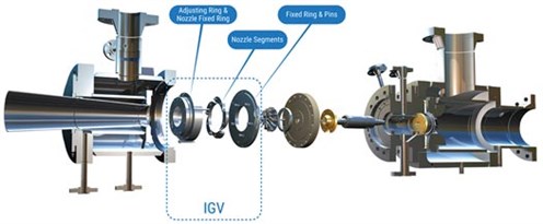 |
| FIG. 9. Inlet guide vane example. Image courtesy of L.A. Turbine. |
LITERATURE CITED
1 Avetian, T. and L Rodríguez, “Fundamentals of turboexpander design and operation,” Gas Processing & LNG, May/June 2020.
 |
LUID E. RODRIGUEZ is a Design Engineer at L.A. Turbine, a Chart Industries Company, responsible for the mechanical design of turboexpanders. Prior to L.A. Turbine, he worked for 10 yr at Sulzer Turbo Services in La Porte, Texas. Mr. Rodríguez is a Texas-registered professional engineer with a BS degree from Universidad Simón Bolívar in Venezuela and an MS degree from Texas A&M University.
 |
RUSTY HOCH is Regional Sales Manager at L.A. Turbine, a Chart Industries Company, responsible for fostering new customer relationships, managing current customer partnerships and providing turboexpander aftermarket services and solutions. Mr. Hoch is an Air Force veteran who holds a BBA degree from Texas A&M University and an MBA degree from Webster University.


Comments