
Are cylinder liners necessary for high-speed reciprocating gas compressors?
Wear is common in reciprocating gas compressors (RGCs) due to sliding and rotational motion of parts. In the design of RGCs, wear study and calculation by empirical formulas are conducted to estimate and forecast the life of the parts. However, wear during real working conditions is different from theoretical estimations and, sometimes, catastrophic failure is experienced during operation due to considerable mechanical or chemical wear.
Wear in the cylinder wall due to reciprocating motion of the piston is a good example of such circumstance and the main subject of this article. Low- and moderate-speed RGCs are normally furnished with a cylinder liner; however, high-speed RGCs may or may not be furnished with a cylinder liner. In this article, the main differences between low-, medium- and high-speed RGCs are discussed; the wear mechanism in the cylinder is explained; the importance of cylinder liners to RGCs is addressed; and the author’s recommendations for decision-making when considering liners are explained.
Standards for RGC operation. The American Petroleum Institute (API) produced API Standard 618 (1964)1 and API Standard 11P (1976).2 These standards are frequently used for the design and manufacture of RGCs. API 618 (Edition 1) was published in 1964 based on the operating experience of 1950s compressor models. During that time, manufacturing and materials technology were not advanced and the speed was limited to 100 rpm, which is why the 1st edition of API 618 covers only low-speed compressors.
Manufacturers encouraged coupling RGCs to gas and diesel engines with speeds of 800 rpm and higher, which increased their size and cost. This led to the publication of API 11P in February 1976, approximately 12 yr after the publication of the first revision of API 618. Moderate-speed units were derived from high-speed units and added to API 618 in 1995.
RGCs are classified into three types in terms of rotational speed, as shown in TABLE 1. High-speed, packaged RGCs for oil and gas service are covered under API 11P, which has been withdrawn by API and replaced by ISO 13631 (2002), “Petroleum and natural gas industries—Packaged reciprocating compressors.”3 The driver can be either an engine or an electric motor. Sometimes they are coupled via a gearbox. Their operating speed is typically 800 rpm–1,800 rpm, based on the author’s experience, with engine drivers above 1,000 rpm and motor drivers of 800 rpm–1,000 rpm.
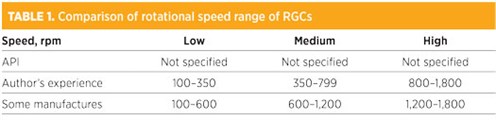 |
High-speed RGCs are skid-mounted and packaged. They are easy to install, easily transportable to different sites due to their modularized and compact design, and have a relatively small CAPEX. High-speed RGCs have higher maintenance costs than low- and medium-speed compressors. Low- and medium-speed compressors run at speeds of 100 rpm–799 rpm. These compressors have lower speed, higher stroke and higher efficiency over a wide range of operating conditions and require less maintenance than the high-speed units because of their lower speed. However, low- and medium-speed compressors usually must be field-erected and require heavy foundations. They have high degrees of vibration and pulsation suppression compared to low- and medium-speed compressors. Large low-speed compressors are shipped to the site as loose items (e.g., throws, frame, driver, etc.).4
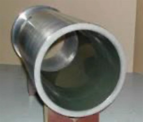
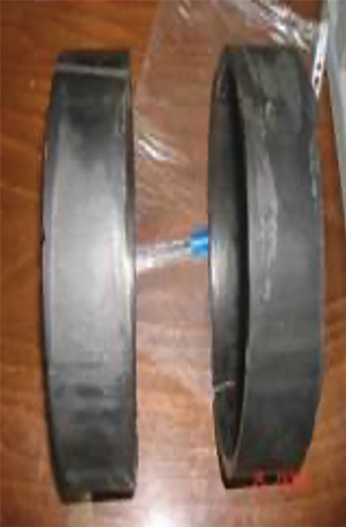
API 618 compressor cylinders are frequently supplied with liners (FIG. 1) to reduce reconditioning costs. RGC cylinder liners are removable in case of accidental scoring or wear over a long period of service. In general, liners are not used in high-speed machines (API 11P/ISO 13631) where the rotating speed is higher than 800 rpm. Liners are almost always used in API 618 compressors, especially in critical services where the gas being handled is corrosive, toxic, low-temperature or high-pressure, and in special designs like free-floating piston.
 |
|
FIG. 1. API 618 compressor cylinders are frequently supplied with centrifugally cast, removable liners to reduce reconditioning costs. |
However, API 618 does not define the meaning of “critical services.” Liners have become a standard design for many refining, gas and petrochemical industry applications, even though the gas involved may not be corrosive, toxic, low-temperature or high-pressure. Some end users insist on liners in their compressors based on maintenance lessons learned. Liners are a key subject during the RGC engineering and procurement stages, and they may increase the CAPEX of RGCs; however, liners have a significant positive impact on OPEX, especially for large or multistage cylinders and where service is critical or special, without any standby. Another benefit of a liner is to reduce the cylinder bore size to meet certain operating capacity conditions. By installing liners with different bore sizes, the same cylinder can be used to accommodate a range of capacity and pressure conditions. This is useful when renting a compressor, as opposed to buying one.5
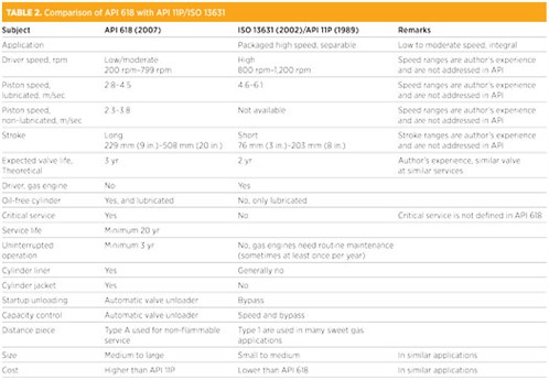
API 618, API 11P and ISO 1363 do not define low-, medium- and high-speed compressors in terms of the piston and rotating speed. Normally, they are defined in the client’s specifications. The main differences between API 618 (5th edition) and API 11P (ISO 1363) are summarized in TABLE 2.
 |
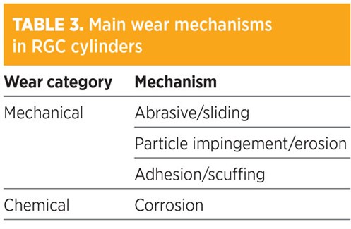
Definition of wear. Wear may be defined as material or mass removal from the surface of any part due to contact with another surface. Wear can also result due to mechanical or chemical behavior of the material. Cylinders experience wear at the point of contact with the piston rings. In horizontal arrangements, cylinder wear is greatest at the bottom because of piston weight. In compressor cylinders, different types of wear can occur, as outlined in TABLE 3.
 |
Sliding wear. Surface-to-surface interactions happen whenever one surface slides relative to another over a distance. Friction between two parts is the main cause of this kind of wear. In RGCs, sliding wear generally happens between parts such as cylinders with piston rings. Also, hard particles may form inside cylinders, which may cause abrasive wear in the cylinder. Cylinders in RGCs are at risk of abrasive or sliding wear due to reciprocating motion and the risk of contacting the piston with the cylinder wall due to wear band ring failure (FIG. 2).
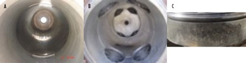 |
| FIG. 2. Cylinder sliding wear (a), piston sliding wear (b) and cylinder wear (c). |
Particle impingement/erosion. This type of wear may be due to different causes:
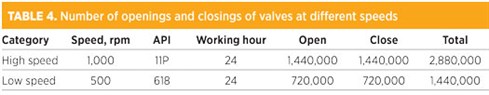
- Solid particles enter the cylinders with gas and impinge on the cylinder from an external source (FIG. 3)
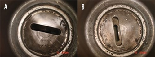
FIG. 3. Solid particles may enter the valve port and cylinders during first startup. - Solid particles from broken parts, such as a broken valve due to fatigue (i.e., high vibration over a period of time), which is common.
API 618 requires valves and cylinders to be designed so that neither the valve guard nor the assembly bolting can fall into the cylinder, even if the valve assembly bolting breaks or unfastens (Clause 6.9.1.5). However, a channel design from the valve port may be needed for the inside of the cylinder, or a special valve bracing bracket may be used.
Based on the author’s experience, many manufacturers deviate from this requirement due to the cost impact on casting or fabrication of the cylinders. If a broken valve is removed from the cylinder, it may drop inside the cylinder and damage the piston and cylinder wall. The author experienced a valve failure due to fatigue, which caused the broken parts of the valve to damage the piston, cylinder head and cylinder wall/liner (FIG. 3B). Note that the cost and time of replacing the cylinder head, piston and other parts are much less than the cost and time required to replace the cylinder.
Adhesion or scuffing. Adhesion or scuffing is defined as local welding between piston rings and the cylinder wall or liner. This is generally caused where lubrication is insufficient and compression temperature is high. Due to high friction and a lack of lubrication, significant heat is generated and microscopic local welding of rings and cylinders occurs. In a high-speed compressor, all cylinders must be lubricated; also, there is no jacket water in high-speed RGCs.
To remove heat from the cylinder, piston and rings due to friction (not gas compression), the vendor must inject a considerable amount of oil into the cylinders. The oil consumption of high-speed compressors may reach to 900 l/mos or higher, depending on the number of throws, the size of the cylinder, the piston speed, etc. Any lack of cylinder lubrication in high-speed compressors can cause catastrophic cylinder and piston ring wear and damage (FIG. 4).
 |
| FIG. 4. Wear band adhesion. |
Corrosion. A complex phenomenon, corrosion sometimes occurs in compressor cylinders due to poor material selection or preservation during shipment, construction or long storage (FIG. 5). It is less likely to happen due to improvements in material science and manufacturing technology.
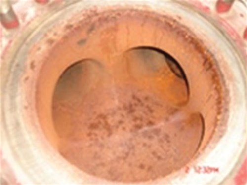 |
| FIG. 5. Cylinder rusting due to poor preservation. |
Wear due to chemical behavior is not considered, assuming that material selection is carried out carefully.
Wear calculation. The wear rate is different in dry and lubricated sliding surfaces; however, general wear depends on many factors such as temperature, pressure, sliding speed, relative hardness, material microstructure, surface finish, sliding distance, etc.
As a good estimation of wear on a macro scale, the Archard equation (Eq. 1) may be used:
W = K × P × V × t (1)
where:
W = Worn volume or wear depth
K = Coefficient of wear
P = Applied load
V = Sliding velocity of piston
t = Running time.
According to Eq. 1, the wear rate of the cylinder, piston rings, wall/liner, etc. are functions of piston speed. Therefore, it is important to clarify the maximum allowable piston speed for lubricated and non-lubricated machines at the early phase of the project. The instantaneous piston speed varies from zero at the end of the stroke [i.e., top dead center (TDC) and bottom dead center (BDC)] to a maximum near the middle of the stroke, where the crankshaft is parallel to ground level. It can be concluded that piston speed changes as a sine wave. The maximum and average piston speeds are calculated as shown in Eqs. 2 and 3:
Vmax = 2∏rN (2)
where:
Vmax = Maximum piston velocity
r = Crank arm length
N = Rotational speed
∏ = Pi.
Vm = 2S [N ÷ (60 × 1,000)] (3)
where:
Vm = Average velocity, m/sec
S = Stroke, mm
N = Rotational speed, rpm
60 = Conversion for changing minute to second
1,000 = Conversion for changing mm to m
2 = In each rpm, the piston travel two times its stroke.
Considering Eqs. 1 and 3, a low-rotational-speed compressor (i.e., API 618, long stroke) with average speed and pressure loading at the wear band is equal to a high-rotational-speed compressor (API 11P, short stroke) and may be expected to have similar sliding wear rates. However, the former does not normally have a cylinder liner, and the risk of other types of wear are still high.
Valves are not the subject of this paper; however, it is worth mentioning that increasing the rotational speed has a significant impact on the valve service life as one of the most critical compressor parts. Each suction or discharge valve in a compression cycle opens and closes one time. The number of openings and closings of a valve in a single stage of a single compressor with two different speeds is shown in TABLE 4.
 |
In an RGC with a constant capacity, if the stroke is decreased and the rotational speed is increased, then reciprocating forces acting on the piston, cross-head, connecting rod, piston pin, etc., will increase and a higher load will be imposed on the crank shaft. In parallel, higher rotational speed causes increased acceleration of gas coming to or exiting from the cylinder via valves, which leads to greater wear of the valve components.
Under constant rotational speed, a compressor with higher stroke causes more wear on cylinder and piston rings. As an example, suppose a packaged, separable RGC (API 11P) with a double-acting, gas engine drive with speed of 1,000 rpm experiences a 1-in. increase in stroke, which causes: 1 in. × 2 × 1,000 rpm × 24 hr × 60 min × 365 d × (1/12) ft = 87,600,000 ft/yr = 26,700,480 m/yr = 26,700.5 km/yr additional movement of the reciprocating parts and the equivalent amount of additional wear. This is about three times the east-to-west distance of Russia—i.e., 10,000 km!
Increasing the cylinder diameter does not impact the velocity or acceleration of the piston. However, the volume of gas displaced by the piston increases significantly. The larger cylinder requires a larger piston, which causes higher piston weight and higher pressure in the wear band ring and cylinder. The cylinder diameter, stroke and piston velocity must be decided carefully to mitigate the risk of wear and vibration and also to minimize clearance losses.
High-speed compressor without cylinder liner. Consider a single-stage, single-acting reciprocating compressor. The theoretical capacity or the displaced volume by piston is calculated as shown in Eq. 4:
Qt = ∏ × (D2/4) × S × N × n (4)
where:
Qt = Compressor theoretical capacity or the displaced volume by piston, m3/min
D = Cylinder internal diameter, m
S = Stroke, m
N = Compressor rotational speed, rpm
n = Number of cylinders
∏ = Pi.
With reference to Eq. 3, if the piston speed is assumed to be constant, then the stroke and compressor rotational speed have a reverse relation. For a constant capacity, to decrease the piston stroke, it is necessary to increase the compressor rotational speed. Decreasing the compressor stroke means decreasing the dimension of the compressor, which results in less material, less space and lower cost. In general, high-speed compressors are cheaper than low-speed API 618 compressors due to their lower stroke and lower dimension.
Adding a liner to the cylinder of a high-speed compressor has a negative impact on compressor performance and volumetric efficiency because the fixed clearance in the valve area is increased (FIG. 6). The valve area cannot be increased to compensate for the clearance loss due to the liner because a larger cylinder is required. A larger cylinder needs a larger piston, and a larger piston means heavier load in the wearing band, cross-head, connecting rod, bearings and crank shaft. Also, a larger piston will increase the clearance loss due to greater gas leakage from the rings.
 |
|
FIG. 6. Adding a cylinder liner results in a higher clearance pocket in the valve area. |
Adding a liner in the cylinder of a high-speed compressor can reduce the volumetric efficiency and flexibility of the variable volume clearance pocket. This is largely why manufacturers of high-speed compressors do not use liners for cylinders.
The volumetric efficiency of a reciprocating compressor is the ratio of the discharged gas from the compressor to the displaced volume of the first stage, as shown in Eq. 5:
ηv = 1 – {[Z1 ÷ Z2] × [(P2 ÷ P1)i]1/γ – 1} C-L (5)
where:
ηv = Volumetric efficiency
Z1, Z2 = Gas compressibility factor at suction and discharge condition
(P2 ÷ P1)i = Compression ratio at ith stage, largest compression ratio
P2, P1= Absolute pressure at discharge and suction, respectively
γ = Polytrophic coefficient = 1.3–1.35
C = Clearance loss (%), to be determined by vendor (e.g., 10% < C < 15%)
L = Ring clearance for lubricated cylinder, 0.05–0.06
L = Ring clearance for non-lubricated cylinder, 0.09–0.1.
It is obvious that if C = 0, then ηv = 1; however, practically, ηv < 1 (e.g., 0.97). Therefore, Eq. 5 can be rewritten as Eq. 6:
ηv = 0.97 – {[Z1 ÷ Z2] [(P2 ÷ P1)i]1/γ – 1} C-L (6)
For ideal and real gas at low pressure, Eq. 7 can be used:
ηv = 0.97 – {[(P2 ÷ P1)i]1/γ– 1} C-L (7)
For Eqs. 4 and 5, the actual capacity of a single-stage, single-acting reciprocating compressor is calculated as shown in Eqs. 8 and 9:
QA = Qt × ηv (8)
Qt = Vs × N × n (9)
where:
Qt = Compressor actual capacity, m3/min
Vs = Displaced volume by piston, m3 = (∏ ÷ 4)(D2 – d2) × S + (∏ ÷ 4) (D2) × S = (∏ ÷ 4)(2D2 – d2) × S
D = Cylinder internal diameter, m
D = Piston rod diameter, m
S = Stroke, m
N = Compressor rotational speed, rpm
n = Number of cylinders
∏ = Pi.
According to Eq. 4, with constant piston speed, high-speed compressors have lower stroke and size compared to low- and medium-speed compressors. Adding a cylinder liner to a high-speed compressor increases the value of valve clearance loss and impacts volumetric efficiency and actual capacity. This is the main reason that cylinder liners are often not used on high-speed compressors.
Cost comparison. In case of damage in a cylinder bore, a liner can be replaced, or the entire cylinder can be replaced or repaired (e.g., by metal spraying). Repairing the damaged cylinder by machining, grinding or metal spraying requires time. In the author’s experience, the metal sprayed on the cylinder bore will peel and flake and give less service life compared to replacing the liner. Repair may require the cylinder bore to be machined to an oversized diameter to accept a liner or larger-size piston rings.
Also, sometimes it is not possible to repair the damaged cylinder due to the cylinder thickness, jacket water location, closeness to the repair shop, etc., and it is necessary to replace the cylinder. Replacing the cylinder is more costly compared to replacing the liner, especially for large-bore cylinders and/or multi-throw configurations. Sometimes it may be difficult or very expensive to order a new cylinder after 10 yr or more because the sub-vendor that casted or forged the original cylinder may no longer be in operation, and a stock cylinder may not be available. GP
LITERATURE CITED
- American Petroleum Institute, API Standard 618, “Reciprocating compressors for petroleum, chemical, and gas industry services,” 5th Ed., December 2007, Errata 2, July 2010.
- American Petroleum Institute, API Standard 11P, “Specification for packaged compressors for oil and gas production services,” January 1989, Revised 1999.
- International Standards Organization, ISO Standard 13631, “Packaged reciprocating gas compressors,” 1st Ed., August 2002.
- Bloch, H. P., Compressors and Modern Process Applications, John Wiley & Sons, 2006.
- Griffith, W. A. and E. B. Flanagan, “Online continuous monitoring of mechanical condition and performance for critical reciprocating compressors,” Proceeding of the 30th Turbomachinery Symposium, Texas A&M University, Houston, Texas, 2001.
 |
SHAHAB ZARDYNEZHAD is a registered Senior Mechanical/Pipeline Engineer in Alberta and British Columbia with more than 29 yr of experience working in the world’s largest oil, gas and petrochemical projects. He has experience in engineering, procurement services, manufacturing, installation, commissioning, startup, reliability, maintenance and operation of pumps, compressors and turbines. He holds a BS degree in mechanical engineering from the University of Petroleum of Iran, an MS degree in industrial engineering from IUST Iran and MS degrees in mechanical engineering and project management from the University of Calgary in Canada. He is also a certified API inspector for rotating equipment.


Comments