
Reduce emissions and save energy with an unconventional flare gas recovery system
An unconventional flare gas recovery system (FGRS) can be designed without a gas compressor to collect the boiloff gas from the ethane tank to the boilers at the utility area. This innovative recovery system will provide significant capital and operating cost savings by eliminating the installation and operation of a gas compressor as part of the conventional FGRS. The FGRS scheme includes the use of a gas ejector with high-pressure motive gas to boost low-pressure ethane flare gas to the intermediate pressure, which is required to return the gas to the boilers at the utility area.
The case study included here explains how the unconventional FGRS was applied at Saudi Aramco’s Yanbu NGL fractionation plant to continuously recover approximately 1.1 MMsft3d of valuable C2+, which is equivalent to 1,961 MMBtu/d in fuel energy savings. The proposed FGRS scheme will also minimize greenhouse gas emissions and provide positive environmental benefits.
Project introduction. Flare systems are essential parts of any oil and gas processing plant. These systems, which essentially consist of flare headers and laterals, liquid knockout drums and flare stacks, serve as one of the last layers of protection for the plant to safely relieve pressure from plant equipment during an overpressure condition. As part of safety requirements, flare headers are normally provided with continuous purging to prevent vacuums within the system, keep air out of the system and prevent possible explosions.
The major component of any conventional FGRS is the gas compressor. It is required to compress the low-pressure flare boiloff gas to a pressure that can return the gas to the process. The recovery gas compressors have recurring maintenance, operating spare and reliability issues, similar to any other rotating equipment in a process plant. It would, therefore, be an attractive and economic venture if the use of a gas compressor can be eliminated from the FGRS without jeopardizing the performance and safety of the system. To this end, a scheme was evaluated using a gas ejector that can provide additional operating flexibility and reliability to the system.
At the Yanbu NGL fractionation plant, the purge gas used is ethane. To ensure no air ingress into the flare headers, a minimum flowrate of purge gas must be continuously maintained for each flare system at the plant. One 100% ethane tank flare system is in use. The system has a flare header of 12 in.–16-in. diameter; therefore, the maximum continuous load of ethane boiloff to flare system is 1.1 MMsft3d. The total flared gas is available to be continuously collected and routed back to the boiler utility area.
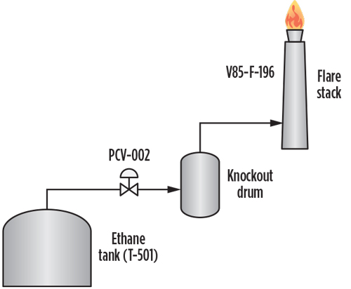
The study revealed that it is feasible to recover the continuous flared gas by connecting new piping from the flare system upstream of the flare knockout drum to the boiler utility area, to allow continuous boiloff and utilize it as fuel for the boilers. FIG. 1 shows a schematic of the ethane tank flare system arrangement at the Yanbu NGL processing facility.
 |
|
FIG. 1. Schematic of ethane tank flare system at the Yanbu NGL processing plant. |
The unconventional FGRS scheme was established and carefully evaluated through hydraulic and process simulations, using both in-house programs and proprietary software,a as described in the following section.
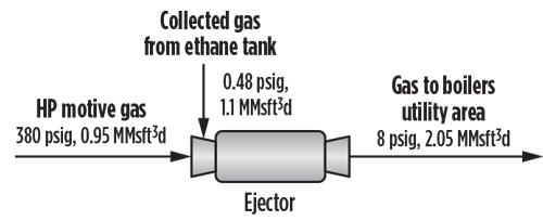
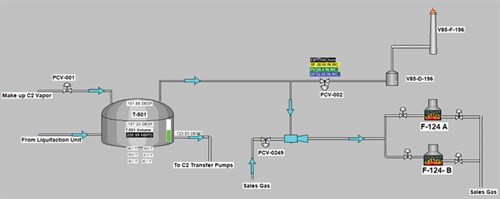
Ejector-based FGRS. The scheme was developed by utilizing a suitable ejector to collect the 1.15 MMsft3d of continuous flare gas at 0.48 psig, using 0.95 MMsft3d of available high-pressure gas as motive gas. The process scheme was modeled, simulated and confirmed possible, using proprietary software.a To this end, a recovery system utilizing high-pressure gas at 380 psig as motive gas—in an ejector to transport the gas from the flare site to the boiler utility area—was established. FIG. 2 shows the calculated flowrates and pressures for the feeds and outlet streams of the ejector. FIG. 3 shows the flow scheme for the ejector-based FGRS.
 |
|
FIG. 2. Calculated flowrates and pressures for the Yanbu FGRS ejector. |
 |
|
FIG. 3. Flow scheme of ejector-based FGRS at the Yanbu facility. |
This flare gas recovery approach is possible based on the fact that there is enough room in the boiler utility area to accommodate the flared gas volume. Flare gas recovery at the plant requires only the means to transport the gas from the ethane tank flare system site to the boiler utility area at the gas plant (a total distance of approximately 1.7 km) within the limited differential pressure. Appropriate pipe sizes within the available differential pressures were determined by careful analysis of the hydraulic simulation results. The results show that 2.05 MMsft3d of mixed high-pressure fuel gas and ethane at 17.5 psig will arrive at 8 psig at the utility area, using 6-in. piping.
In the proposed recovery system, the pressure control valve already exists between the flare gas offtake points and the flare knockout drum. This design maintains a slight positive pressure in the flare header and prevents both an undesirable opening condition for the control valve and the release of ethane to the flare system. Whenever the amount of gas released into the flare system exceeds the capacity of the recovery system (1.1 MMsft3d), a pressure control valve on the flare recovery line will act to maintain the flow at 1.1 MMsft3d. The proposed recovery scheme is illustrated by the flow scheme shown in FIG. 3.
Simulation results. The ethane recovery system is designed to take ethane from the ethane storage tanks and compress it for firing at 1.5 psig–2 psig and for delivery at approximately 3.7 psig to the two boiler skids.
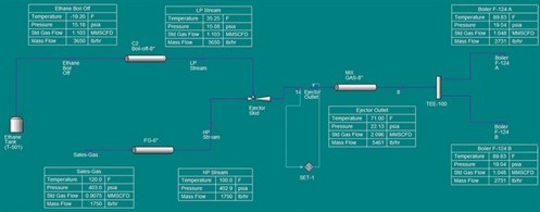
The ethane recovery system was simulated, using proprietary softwarea to perform the hydraulic analysis and predict the process conditions (FIG. 4). Actual pipe lengths for the existing and new pipes are taken from an isometric drawing, to account for the pressure losses from the ethane tank to the boilers at the utility unit. The design flow used to size the recovery system is 0.4 MMsft3d–1.1 MMsft3d, with an ethane composition of 98%.
 |
|
FIG. 4. Ethane recovery system simulation. |
The results of the hydraulic analysis indicated that new and existing pipes are of adequate size to avoid backpressure on the ethane tank under normal operation, and they are able to deliver the mixed gas stream at a pressure of 3.7 psig to the boiler skids. A sensitivity analysis, including summer and winter conditions, was also run to calculate the system pressure drop. The calculated pressure drop for the 8-in. ethane line from the tank vapor line to the ejector skid inlet is 0.1 psig. The simulation results also validate the pressure drop calculation performed by a third party.
Takeaway. The established FGRS scheme has multiple economic benefits. First, it will recover approximately 1.1 MMsft3d of valuable C2+, which is equivalent to 1,961 MMBtu/d in fuel energy savings.
Second, the system will operate without any energy consumption or rotating equipment (all installations are static equipment—i.e., no moving parts). The system will utilize energy that would otherwise have been wasted or flared since plant startup.
Third, the flare gas recovery system will improve the reliability and life span of the flare tip, thereby reducing the recurring cost of flare tip replacements. The proposed system will minimize greenhouse gas emissions and provide a positive environmental impact.
Finally, operation of the established FGRS at the Yanbu NGL fractionation plant will provide an operating experience base within Saudi Aramco for other facilities to adopt. GP
NOTES
a HYSYS
 |
ABDULAZIZ H. AL-TIJANI is an Engineering Specialist at Saudi Aramco’s Process and Control Systems Department in Dhahran, Saudi Arabia. He holds a BS degree in chemical engineering from King Fahd University of Petroleum and Minerals (KFUPM) and a MS degree in oil and gas surface facilities from KFUPM (in partnership with IFP). Mr. Al-Tijani supports company operations and project design, mainly in flare and relief systems and flare gas recovery applications. He supports Saudi Aramco and joint-venture oil and gas operational facilities, pipelines, process simulations and various phases of projects.
 |
IRFAN ASHIQ is a Senior Operations Engineer for Saudi Aramco at the Yanbu NGL fractionation plant. He has more than 22 yr of professional experience in process design, operation and commissioning for upstream oil and gas, heavy oil and petrochemicals. Prior to joining Saudi Aramco, he was the Lead Process Engineer at SNC Lavalin in Canada and a Senior Process Engineer at Propak Systems Ltd. in Canada. He holds an MS degree in chemical engineering from the University of Calgary in Canada and a professional certification from the Association of Professional Engineers and Geoscientists of Alberta (APEGA).


Comments