
Natural gas liquids extraction and separation
Natural gas liquids (NGL) are a group of hydrocarbons, sometimes referred to as purity NGL, that includes ethane, propane, normal butane (n-butane), isobutane and natural gasoline (pentanes plus). NGL made their inroad into fuel markets in the 1910s, when the issue of gasoline loss while stored under normal conditions was addressed, leading to a way to bottle liquid gas.
NGL are produced predominantly in gas processing plants and, to a lesser extent, in refineries as homogeneous liquid blends of purity NGL. The NGL extracted from natural gas make up the so-called Y-grade NGL from which ethane, propane, n-butane, iso-butane and pentanes plus are separated by fractionation in a distillation unit. A subset of NGL is liquid petroleum gas (LPG). LPG is a blend of propane, n-butane and i-butane.
All natural gases contain NGL. Although the quantity of liquids is not always great enough to be economically recovered, there are cases where NGL extraction is desired either to meet sales specifications (minimum and maximum high-heating-value requirements) or to produce transportable gas—i.e., a gas that can be piped without hydrocarbon condensation along the pipeline (dewpoint control).
This article provides an overview of technology for the recovery of NGL, as well as a brief discussion on the economic reasons that justify the extraction of NGL from natural gas and provide the foundation for different processing facility configurations.
Fundamentals of NGL economics. NGL have a wide variety of applications, including feedstock for petrochemical production, as fuel for vehicles and as specialized fuels for space heating and cooking.
Among individual NGL, ethane has the largest share of NGL field production, followed by propane. Together, they make up 90% of the NGL barrel. Ethane is largely used to produce ethylene, the monomer used to produce polyethylene, ethylene oxide, ethylbenzene and dichloromethane, which are raw materials for the production of a wide variety of everyday objects.
Propane is the precursor of polypropylene, which is used to produce plastics, resins, rubbers and other materials. It is also used as a residential and commercial heating fuel, as a drying agent for crops, as a ripening agent for fruit, and so on.
N-Butane is used to produce butadiene, the key component in synthetic rubber. Butane is also used during winter as a fuel additive in motor gasoline. I-Butane is mainly used in refineries as feedstock for the alkylation process to produce alkylate. It is also used in refrigerators, as fuel, and as propellant in cooking spray and hairspray. Pentane is used as a blending fuel in refineries to make motor gasoline, as petrochemical feedstock and as diluent for heavy crudes.
As can be inferred, NGL markets are rather convoluted as they entail five different, volatile markets sharing a common source of supply. Moreover, the transportation and storage of NGL are expensive as they require relatively high pressure and low temperature to be maintained in the liquid state.
Since NGL are mixtures with low density and low viscosity, they can be used as diluent for heavy crude oil so that it can be efficiently transported via pipeline. When the crude oil is worth more than the weighted average value of NGL as gas, the condensate can be used for crude spiking. In doing so, not only are the NGL valued as crude, but also the crude may be upgraded due to the increase of API gravity and sold at a higher price per barrel.
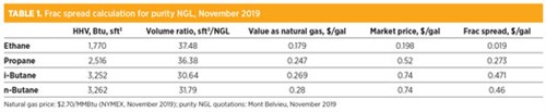
Recovery of NGL might be economically attractive if they are worth more than their value in sales gas; the relative value of liquids against gas is given by the frac spread—i.e., the difference between the NGL market prices and the value of retaining them in the natural gas. Eq. 1 explains how the frac spread is calculated:
Frac spread = $l – $g × HHVCi × Fi ÷ 1,000,000 (1)
where:
$l = Price of a purity NGL, $/gal
$g = Price of natural gas, $/MMBtu
HHVCi = High heating value of the purity NGL, Btu/sft3
Fi = Gas volume to liquid volume conversion ratio.
An example of a frac spread calculation is provided in TABLE 1. As shown, in November 2019 the market values of purity NGL in the U.S. exceeded their values as natural gas in the U.S., providing gas processors with an economic incentive to extract C3+ and reject C2, since the frac spread of the latter probably does not cover its transportation costs (roughly $0.05/bbl).
 |
The frac spread is a key element of the gas processing plant. However, to achieve effective production planning, other factors must be considered. Among these, the following are spotlighted:
- Liquid-to-gas ratio. This ratio is expressed either in gal of liquid per 1,000 ft3 of gas (gal/min) or in m3/MMm3. Generally, a liquid content equal to or greater than 3 gal/min makes NGL recovery profitable.
- Energy content of raw natural gas. NGL enter the processing plant as gas and leave as liquid, so less hydrocarbons are left in the gas, which shrinks both in volume and in energy content. The minimum heating value (typically 1,030 Btu/sft3) required for the sale gas may limit the level of NGL that can be extracted from a specific stream of inlet gas, while the dry gas pipeline specification may limit how much ethane can be left in the residue gas.
- Shrinkage or extraction loss. The reduction of natural gas value as a result of NGL recovery must be taken into consideration for production configuration decision-making.
If a gas processor finds that ethane recovery is not profitable at a particular time, then the operator will choose to leave ethane in the residue gas (or “tailgate gas”). This operating mode is known as ethane rejection mode.
Since the purity NGL markets are volatile markets, the ethane price may in time rise to a level that makes ethane recovery desirable. The processing plant, therefore, should be designed to be capable of either rejecting ethane when its price is too low or producing ethane when the price is high enough to justify its extraction from raw gas.
Liquid extraction processes. The recovery of Y-grade NGL is typically carried out in a central processing facility at field level; however, not every central processing facility splits NGL into individual components. Sometimes, the Y-grades are delivered to a central fractionation plant (straddle plant) located close to an end market or hub.
The extraction of NGL might be necessary either for meeting the sales gas specification or for producing a gas suitable to be transmitted via pipeline without slug formations (two-phase flows where chunks of liquid hydrocarbons run along the line with a velocity comparable to that of gas). In these cases, the extraction of NGL is done in a hydrocarbon dewpointing process unit.
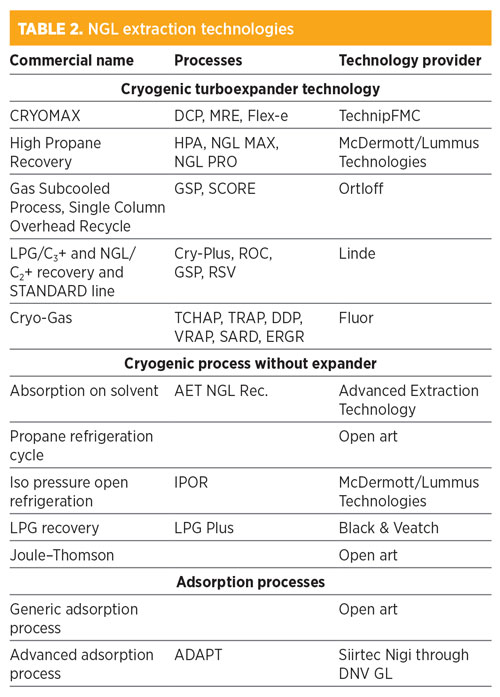
The process technologies used to carry out an NGL extraction can be categorized into three groups: cryogenic turboexpander recovery technology, mechanical refrigeration and absorption processes. TABLE 2 provides an overview of the best-known NGL technologies available at present.
 |
Cryogenic turboexpander technologies. The base diagram of a turboexpander process for a rich natural gas is shown in FIG. 1. It consists of a cooling train followed by a stabilization column. The condensation of NGL is achieved by combining heat integration and external refrigeration with propane. Methane is stripped from the liquid during ethane extraction in the stabilization section, and ethane is stripped during ethane rejection mode.
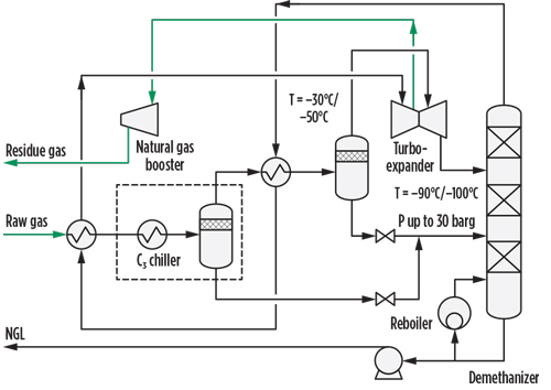 |
| FIG. 1. Turboexpander process flow diagram. |
The raw gas at high pressure (often 70 barg) is first cooled against the de(m)ethanizer overhead stream, and is then cooled to approximately –40°C in the evaporator of a propane closed-loop refrigeration package. The resulting two-phase flow is separated in the first separator; the liquid is sent to the de(m)ethanizer, and the gas (after further cooling and separation) is expanded, generally to 20 barg–30 barg, in a turboexpander, where its enthalpy variation turns into mechanical work.
The cold two-phase stream from the expander heads to the de(m)ethanizer, where the light components dissolved in the condensate are stripped out according to the operating mode (C2 extraction or rejection mode). The Y-grade NGL are extracted from the bottom of the de(m)ethanizer and routed to the fractionation section of the facility, while the residue gas is compressed in the compression end of the turboexpander.
Since only a fraction of the mechanical work produced by the expander can be transferred to the compressor, the pressure of the residue gas is significantly lower than that of the raw gas. To feed the downstream pipeline, a booster compressor must be installed to restore the pipeline pressure. The booster compressor is a major consumer of electric power in the process plant. Some processing technology (e.g., Fluor’s TCHAP) has been specifically developed to minimize this recompression cost.
It is worth mentioning that in cryogenic service, the most widely used heat transfer equipment is the brazed aluminum heat exchanger (BAHE) or the more recent printed circuit heat exchanger (PCHE). A BAHE is a stack of alternating layers of parting sheets and heat transfer fins. Each layer is provided with inlet and outlet ports for the streams and is sealed along the edge by means of a side bar, as shown in FIG. 2. The block of layers is bounded by cap sheets at the top and bottom and is provided with headers and nozzles for the entrances and exits of process flows.
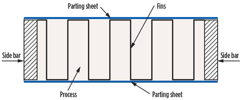 |
| FIG. 2. Key elements of a BAHE. |
BAHEs feature a large surface area per unit volume, high heat transfer, a minimum temperature approach as low as 1°C, and the ability to handle multiple process streams. Compared with a shell-and-tube heat exchanger, a BAHE can be 80%–85% smaller and lighter. BAHEs are generally made of aluminum. Since aluminum is prone to mercury corrosion, the use of BAHEs require a mercury removal unit in the pretreatment section of the central processing facility. Moreover, aluminum is a weak material, making BAHEs vulnerable to thermal shocks during startup and shutdown operations.
PCHEs are compact heat exchangers without gaskets, joints or welds. The core of the heat transfer is obtained by means of diffusional bonding, which is a solid state joining process. A number of platelets are stacked in a pile, pressed together, heated at 50%–70% of the material melting point and then allowed to rest so that the material grains can grow and fill the gaps between the surfaces. In doing so, a monolithic block of core heat exchange is obtained. The channels for fluid flow are obtained by chemical etching or pressing.
Designs to accommodate market volatility. When designing central processing facilities for NGL production, processing facilities must be made to accommodate both the ethane extraction and ethane rejection modes to tune the plant operation to market volatility. Rejecting ethane entails a partial loss of propane, which is generally more valuable as a liquid than as natural gas. Therefore, a design goal would be to maximize the propane recovery while ensuring the maximum ethane rejection.
The different ways in which these objectives have been pursued has given rise to different distinctive features of the various processing technologies. The fundamental concepts underlying these different ways can be traced to the basic concepts outlined in the following sections.
Dual column. A dual column consists of the installation of an absorber tower between the turboexpander and the deethanizer (FIG. 3A). A cold, ethane-rich stream coming from the deethanizer is pumped to the top of the absorber, and the bulk of the C3+ rich stream is extracted from the bottom. Generally, the dual column also entails the dual reflux concept for the bulk removal of NGL in the absorber. In this arrangement, the deethanizer overhead gas is partially condensed, and the liquid is used to reflux both the deethanizer and the absorber towers. In the dual-column, dual-reflux configuration, as much as 99% of propane can be recovered.
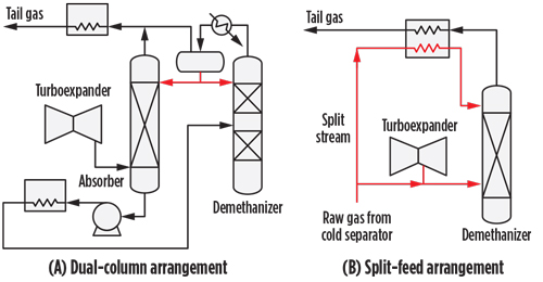 |
| FIG. 3. Dual-column and split-feed arrangements. |
Split-feed gas subcooled process. A slipstream (FIG.3B), typically 15%–30% of the main stream exiting the separators of the cooling train, is subcooled against the cold residue gas and refluxed to the de(m)ethanizer tower (in the case of a single-column arrangement) or to the absorber tower.
Tailgate gas recycle. A slipstream of compressed tailgate gas is cooled in the feed multi-stream plate-fin exchanger, expanded and fed to the top of the de(m)ethanizer. This arrangement improves the C2+ extraction.
Once the Y-grade NGL have been extracted from natural gas, each purity NGL is obtained by separation of the Y-grade in the fractionation end of the production chain. The fractionation is accomplished by means of a direct sequencing operation of distillation, in which the lightest component is taken overhead in each column. Ethane is first separated from the liquid blend, and then propane, n-butane, iso-butane and natural gasoline are separated in sequence.
Absorption on solvent. In this process, a stream of gasoline (C5+) is used as solvent for extracting NGL in a regenerative absorption process where the raw gas is contacted counter-currently with a cold lean solvent. The rich solvent drawn from the bottom of the absorber is regenerated in a fractionation tower and recycled back in the absorber. The refrigeration duties required to reflux the columns are provided by a propane refrigeration cycle.
Arguably, this process is less efficient and more expensive relative to the more competitive and simpler expander plant. This explains why few industrial NGL plants are based on this technology.
Mechanical refrigeration. In this process, NGL are partially liquefied by cooling natural gas to a temperature as low as –37°C to –40°C against an evaporating refrigerant fluid, normally propane, in a kettle-type heat exchanger of a closed-loop refrigeration system. Part of the refrigeration duty is recovered in the gas-gas heat exchanger (GGHE), where the raw gas is cooled against the residue gas from the low-temperature separator (LTS) (FIG. 4).
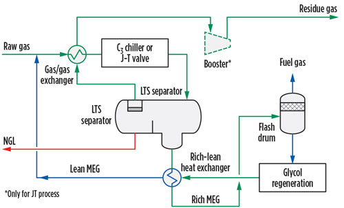 |
| FIG. 4. Simplified PFD of a mechanical refrigeration plant. |
During the cooling step, the gas crosses the hydrate formation envelope and the risk of heat transfer equipment clogging increases; therefore, a hydrate inhibitor must be injected upstream of the GGHE. The inhibitor can be either methanol or glycol—mainly monoethylene glycol (MEG). The former is a relatively volatile chemical; therefore, MEG is generally preferred to methanol. The mechanical refrigeration is, in practice, an isobaric process; therefore, it can be implemented only if the operating conditions fall beneath the cricondenbar.
Joule–Thomson (JT) process. In this process, the gas refrigeration is achieved by exploiting the cooling effect caused by the pressure drop across a throttling valve (JT control valve). The process scheme is similar to that of mechanical refrigeration. Indeed, in the JT process scheme the mechanical refrigerator is replaced with the JT valve.
As the pressure let down is an isoenthalpic and isoenthropic transformation, the final temperature achievable with this process is lower with respect to the external refrigeration, but higher compared to the expander technology. Therefore, the JT process allows the recovery of a greater quantity of NGL than the external refrigeration with propane, but a smaller quantity than the expander.
For tight pressure difference between the raw gas and the residue gas (the majority of cases), the JT process will eventually require the installation of a booster compressor to restore the gas pressure, with sizeable OPEX penalization.
Adsorption on silica gel. Adsorption on silica gel is a separation process (FIG. 5) based on surface chemistry, more specifically on physi-sorption consisting of hydrocarbon and water bonding on hydroxyl groups distributed throughout the surface of the silica gel. Being an amorphous material with mesopores of approximately 20 Å, the pores of the silica gel are also the locus of C6+ capillary condensation; this characteristic enhances the efficiency of natural gasoline separation.
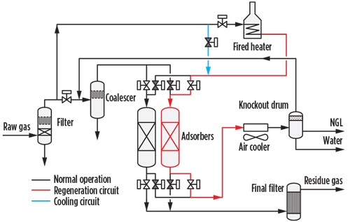 |
| FIG. 5. Process scheme for adsorption on silica gel. |
By increasing the temperature, the interactions between hydrocarbons and silica gel loosen. After all the sorbent hydroxyl groups have been engaged and the bed has become saturated, the adsorbent can be regenerated by heating. Overall, the removal process with silica gel is a dynamic process, where the adsorption stage at temperatures lower than 38°C for a single bed is followed by a regeneration stage at 230°C–270°C.
A silica gel plant consists of at least one fixed-bed column in adsorption mode, one in regeneration mode and one in cooling mode. The continuity of the operation is achieved through sequencing of the columns.
The ADAPT technology utilizes the heat pulse technique, which consists of heating up only a portion of the bed and then exploiting the heat accumulated in this portion to heat up the remaining part of the bed. This technology makes possible the regeneration and cooling in a single column. In doing so, the equipment count and the related, costly cyclic valves and headers are considerably reduced, with sizeable CAPEX savings.
Recently, the ADAPT technology has been extensively implemented for dewpoint control for international transmission of more than 125 Bm3/yr of natural gas through long, submarine pipelines without intermediate recompression facilities. This process requires deep NGL removal to avoid slug formation in the pipelines. GP
 |
LORENZO MICUCCI is a Senior Director at Siirtec Nigi SpA. He has more than 30 yr of experience in the engineering and contracting industry, most of which have been spent in the natural gas sector. In 2001, he joined Siirtec Nigi in Milan, where he directed the process design and operations department and the research and development department. During his time as R&D head, three patents have been granted to Siirtec Nigi, two of which have been implemented on an industrial scale. At present, he is the Senior Director of the technology and marketing departments. Mr. Micucci also worked for Saipem (Snamprogetti) as a Plant Designer for integrated gasification combined cycle and gas-to-liquids plants. He holds an MS degree in chemical engineering from the University of Bologna in Italy and is enrolled as a Qualified Engineer in the Register of Milan Order of Engineers.


Comments