
Increase separation efficiency with enhanced slug catcher internals
Gas facilities use slug catcher vessels to separate arriving gas and liquids. These vessels are typically three-phase separators designed with vane-type mist eliminators. Mist eliminators are not highly efficient in eliminating the liquid carryover from the slug catchers, which will affect downstream separation processes, such as acid gas removal units.
This article discusses enhancements created for the slug catcher’s internals to achieve higher separation efficiency and minimize the process design, sizing, material grade and future inspection and maintenance impact on downstream processing units at Saudi Aramco’s Tanajib gas plant project in Saudi Arabia.
Issues with existing slug catcher system. Highly effective separation of oil and gas from different impurities during upstream operations is a matter of paramount importance. All downstream activities and the process equipment service life depends on the purity level obtained in these first steps.
Historically, slug catcher vessels designed with vane-type mist eliminators are not very effective in eliminating the liquid carryover from the slug catchers. The impurities in liquid carried over have a direct negative impact on downstream separation processes (e.g., acid gas removal units), directly affecting the process design, sizing and material grade selection. Simultaneously, the entrained solid particles can cause fouling of the demisting mesh pads and other downstream components, significantly increasing inspection and maintenance costs and timelines.
At the Tanajib gas plant, it was found that mist eliminators or a vane pack alone were not effective in the separation of small liquid droplet sizes (i.e., smaller than 2 µm); therefore, they were not capable of removing most of the droplets, resulting in a very low separation efficiency and high liquid carryover. When the operating pressure was above 870 psig/60 barg (typical for inlet facilities), the droplets were usually smaller and the efficiency of separation was, therefore, vulnerable. Furthermore, the plant’s processing capacity was often reduced to minimize the accumulated liquids in the downstream scrubber of slug catchers, with frequent draining required for this scrubber.
With myriad problems faced in the Tanajib plant’s original slug catcher design, the following design considerations were reviewed extensively, which resulted in the following stringent design requirements:
- Maintain the liquid carryover from the slug catchers equal to or below 0.1 gal/MMsft3.
- Maintain separation efficiency of 98% for droplets larger than 10 µm.
Existing slug catcher designs. Two designs for slug catcher configurations are discussed in the following sections.
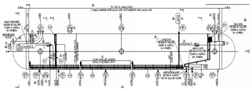
Slug catcher 1 design. Slug catchers in many existing facilities are designed with vane-type mist eliminators (FIG. 1). The specified efficiency of 98% for droplets larger than 10 µm and carryover of liquid < 0.1 gal/MMsft3 required for the Tanajib plant would not be achieved using a vane pack mist eliminator, mainly because of the very high operating pressure of the slug catchers.
 |
| FIG. 1. Slug catcher example from existing facilities. |
Historically, a vane pack (FIG. 2) was found to be unsuitable for operating pressure above 60 bar due to the fact that a small liquid droplet size will be expected due to the high pressure of the vessel. The vane pack will not be capable of removing most of these droplets, resulting in very low separation efficiency and high liquid carryover.
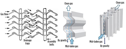 |
| FIG. 2. Typical vane pack configuration. |
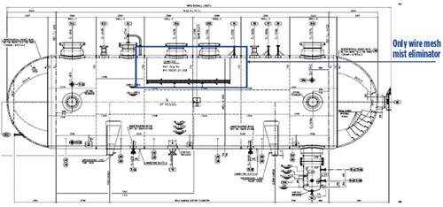
Slug catcher 2 design. In a second slug catcher design configuration, the existing design had only a wire mesh mist eliminator at the gas outlet nozzle. Due to the high gas load factor, the mist eliminator would not be able to achieve the required separation efficiency (FIG. 3).
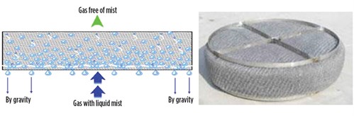 |
| FIG. 3. Typical wire mesh mist eliminator configuration. |
Design improvements. Improvements to the designs of both slug catchers were implemented, as outlined in the following sections.
Slug catcher 1 improvements. To achieve 98% efficiency (for droplets > 10 µm) and 0.1 gal/MMsft3 carryover, axial cyclonic mist eliminators were deployed to further increase slug catcher performance. The top section of the calming baffle was equipped with a proprietary, fouling-resistant vane packa preconditioner. This supports the demisting operations by coalescing the liquid droplets to form larger aggregates that are easier to be captured.
Additionally, a horizontal-flow axial cyclone was identified as an ideal high-capacity system able to remove all liquid droplets while withstanding fouling.b
Slug catcher 2 improvements. To achieve 98% efficiency (for droplets > 10 µm) and 0.1 gal/MMsft3 carryover, a cyclonic mist eliminator design was found to be an ideal solution based on design validation. The same horizontal-flow axial cycloneb was used as for slug catcher 1.
Design validation. The design was validated by simulating the coalescing and separation efficiency by a computation fluid dynamics (CFD) model. In the CFD study, the following assessments were carried out for the performance of the slug catcher:
- The separation of two-phase flow consisting of gas and liquid, with single-phase gas flow simulations.
- The effect of gas flow on liquid interface.
- Carryover of liquid particles.
The CFD simulations proved that two perforated inlet distribution baffles, together with the proprietary vane packa and the horizontal-flow axial cycloneb deck at the outlet nozzle of the slug catcher, provided outstanding demisting performance that met the requisite separation efficiency (FIG. 4).
 |
| FIG. 4. Illustration for a slug catcher with baffles and an axial mist eliminator. |
The CFD also proved that the particle tracking study for gas-liquid separation revealed that only 98% of liquid droplets carryover of 10 µm will reach the proprietary vane pack.a Heavier liquid droplet sizes above 250 µm, separated due to their gravity along the perforated baffle, will not reach the proprietary vane packa and will eventually collect at the bottom of the vessel.
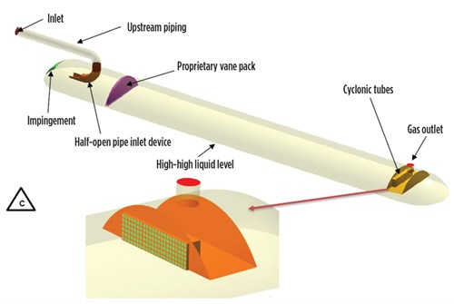
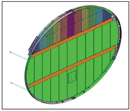
Internals description. The following internals were incorporated in the slug catcher design (FIG. 5) to meet the liquid carryover with gas less than or equal to 0.1 gal/MMsft3:
 |
| FIG. 5. Revised slug catcher design drawing with new internals. |
- Feed inlet device: half-cut elbow open pipe at inlet
- Perforated inlet distribution baffles
- Proprietary vane packa
- Axial cyclonic mist eliminator (proprietary horizontal-flow cycloneb).
The new feed inlet device induction has a large settling area before the calming baffles. The calming perforated baffles were installed after the inlet nozzle. They ensure proper distribution of gas streams entering the mist eliminator and optimize liquid residence time.
The first perforated baffle is a half-diameter baffle, and the second is associated with the proprietary vane pack,a as shown in FIG. 6.
 |
| FIG. 6. Proprietary vane-type mist eliminatora preconditioner. |
The proprietary vane pack preconditioner at the inlet nozzle area is situated on top of the second perforated baffle. The preconditioner ensures the capture of small droplets that coalesce into large droplets, which will further pass with gas entering the cyclone mist eliminator and ensure the removal of small droplets with a cyclone mist eliminatorb (FIG. 7).
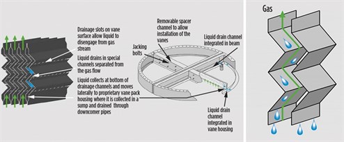 |
| FIG. 7. Simple proprietary vane pack profile with countercurrent drainage of liquid from the vane surface. |
The axial cyclone mist eliminatorb (FIG. 8) is placed at the gas outlet nozzle. The centrifugal forces of the cyclone combine with the high separation efficiency of the mist eliminator. The mist eliminator combines axial cyclonic and cross-flow separation technology to create an efficient, high-capacity separator.
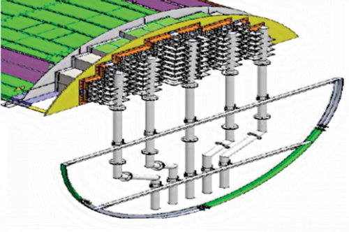 |
| FIG. 8. Cyclone mist eliminator. |
Takeaway. A primary concern at the beginning of the Tanajib project was to overcome the perennial problem of separation inefficiencies and fouling issues in slug catchers with conventional mist eliminators. The typical design was ineffective in eliminating the liquid carryover that affected the downstream separation processes at existing plants.
The appropriate internals selected and performance values set for the slug catchers, as discussed in this study, resolved the impacts on the downstream processes. Accurate CFD analysis has proven beyond a doubt that these enhancements to the slug catchers will help avoid fouling issues and associated pressure-drop scenarios affecting unit performance.
The methods and means adopted have created a superior solution to the existing design problem at the Tanajib gas plant, and could provide a retrofit solution for many existing gas plants. GP
NOTES
a Mellachevron vane pack
b VersiSwirl
 |
SHUJA ALHARBI is a Saudi Aramco employee with a BSc degree in mechanical engineering. He is a certified PMP with more than 13 yr of experience in the oil and gas industry, turbomachinery and static equipment.
 |
TURKI ALGHAMDI is a Saudi Aramco employee with a BSc degree in chemical engineering. He specializes in natural gas and NGL fractionation processing facilities with experience in project management, phase design, construction management and facility startup.
 |
ABDULLAH ALHAZMI is a Project Engineer at Saudi Aramco with a BS degree in applied mechanical engineering from King Fahd University of Petroleum and Minerals. He started his career as a Maintenance Engineer at the Shedgum gas plant and is now a Project Engineer at the Marjan project. He holds PMP and SMRP certificates.


Comments