
The natural gas dehydration process
Natural gas from wells invariably contains humidity. Gas also becomes wet in the sweetening unit of a gas processing facility when it comes into contact with the aqueous solution of a solvent, such as methyl diethanolamine (MDEA), used to remove the acid gases contained in the raw gas.
Water must be removed from natural gas because its possible condensation may result in several problems:
- Corrosion of pipelines in the presence of CO2. CO2 dissolves in condensed water, forming carbonic acid (H₂CO₃), which dissociates in bicarbonate (HCO₃–), carbonate (CO₃²-) and hydrogen (H+) ions. The latter is reduced at the steel surface to form H₂ (2H+ + 2e- → H₂). The two electrons needed for reducing H+ are donated by iron (Fe), which dissolves into the aqueous solution (Fe → Fe²+ + 2e–). For pipeline transportation, the allowed residual humidity generally ranges from 1 lb/MMsft³–7 lb/MMsft³, depending on the environmental conditions.
- Slugs formation. In two-phase flow, liquid waves can reach the top of the pipework encroaching the gas cross-section. When this happens, liquid slugs travel in the same direction as the stream, with relatively high velocity, albeit lower than that of the gas. This results in vibrations and mechanical shocks to the piping fittings (e.g., bends and valves). The fittings superimpose a change to the direction of the velocity vectors. The change of the flow direction generates the thrusts on the piping walls according to the macroscopic momentum balance. Since the slugs are randomly formed, their impingement on the piping/equipment wall may result in dangerous vibrations and mechanical stress on the materials of construction.
- Hydrates formation. In natural gas processing, hydrates are hard crystalline structures wherein water molecules encompass molecules of CH₄, C₂H₆, CO₂ or H₂S, which are trapped in molecular “cages.” The water molecules of the reticular structure are tied to each other by H₂ bonds, and they are tied to the guest molecules through van der Waals interactions. These solid structures are a source of erosion and plugging. This latter is particularly troublesome, as decomposition of hydrates during removal can generate large volumes of gas with explosion hazards.
In addition to the above challenges, water vapor increases natural gas volume while decreasing heating value. It can also cause plugging in cryogenic plants, which call for a water dewpoint specification of less than –100°C. These issues can be effectively addressed by removing the humidity contained in natural gas by means of gas dehydration processes. These processes can be grouped into two categories: absorption on glycol and adsorption on solid sorbent.
Absorption on glycol. The most-used glycols are diethylene glycol (DEG) and triethylene glycol (TEG). In the glycol molecules, hydroxyl groups (–OH) and ether functional groups (–CH₂-O-CH₂–) are present. These groups give rise to H₂ bonds, which explains their remarkable hygroscopicity and their desiccant properties.
Since their molecular weight is greater than water, the glycol molecules boil at a comparatively higher temperature. Glycols can be easily regenerated by distillation. It should be observed that both DEG and TEG are subject to thermal degradation; therefore, the distillation temperatures must be kept below the initial decomposition temperatures—i.e., 328°F (164°C) and 404°F (207°C), respectively—which are lower than their normal boiling points.
Generally, DEG is preferred in hydrates inhibition service where the concentration of the lean glycol (i.e., the glycol coming from the regeneration unit) is required to be in the 85%–95% range and can be regenerated at relatively low temperature. TEG is preferred in gas dehydration service.
Dehydration with glycols is a regenerative absorption process. Generally, it includes a high-pressure absorption column (contactor) where gas at high pressure contacts, in countercurrent, with a stream of lean glycol. After absorbing the water contained in the gas, the lean glycol becomes rich glycol—i.e., water-diluted glycol to be sent to the regeneration unit.
The contacting internals may be trays, random packing or structured packing. The latter is preferred for its specific gas capacity and low glycol entrainment, which require a comparatively smaller contactor diameter. Free water and condensate possibly entrained in the raw gas are knocked out in a separator upstream of the contactor.
As the regeneration step is carried out at near-atmospheric pressure, the high-pressure rich glycol withdrawn from the contactor bottom is let down through a level control valve (FIG. 1). The resultant two-phase flow is then routed to the glycol flash drum, where the absorbed hydrocarbons and part of the inert gas are separated from the rich glycol.
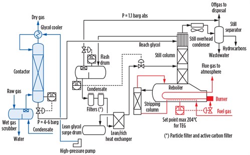 |
| FIG. 1. The TEG dehydration process. |
After filtration and pre-heating, the rich glycol is sent to the still column for water-glycol separation.
The cost-effective design of a gas dehydration unit is the result of the optimum combination of the glycol circulation rate, the lean glycol concentration, the contactor temperature, the stripping gas flowrate and the number of contactor trays or the number of height equivalent to a theoretical plate (HETP) for structured packing.
FIG. 2 shows that by increasing the glycol flowrate, the dewpoint depression (i.e., the difference in dewpoint temperature between the gas entering and leaving the contactor) increases for a given lean glycol concentration.
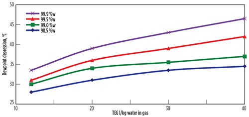 |
| FIG. 2. Effect of glycol rate and glycol purity on dewpoint depression. |
For a given flowrate, the dewpoint depression increases with glycol purity. Since the rich glycol must be pressurized up to the operating pressure of the contactor and since the duty of the reboiler is correlated to the glycol flowrate, the lower the glycol flowrate, the lower the energy consumption of the gas dehydration process. Therefore, a sound design practice aims to achieve the highest possible glycol purity.
The glycol purity can be increased beyond the purity attainable with a distillation operation by sequencing the still column with a small stripping unit (also known as a Stahl column), where water is further removed by means of a stripping gas (typically fuel gas). The wet stripping from the Stahl column is sent to the still column and ends up as offgas for disposal at a pressure close to atmospheric. Typically, the offgas is flared because the pressure is too low to be used as fuel.
FIG. 3 shows how the glycol purity rises with increased stripping gas. However, the curve tends to flatten out. Beyond 30 sm³/m³ of TEG, the gain of glycol purity becomes marginal. Therefore, continuing to increase the stripping gas flowrate does not make economic sense, as valuable fuel gas would be wasted.
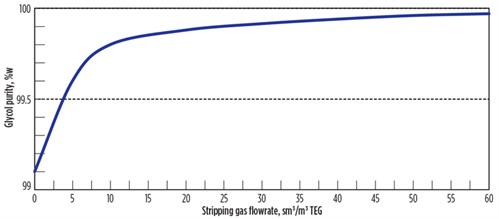 |
| FIG. 3. Effect of stripping gas on glycol purity. |
Advanced technologies have been developed to attain a glycol purity greater than 99% without using an external stripping gas. One processa makes use of a water exhauster where part of the vapor in equilibrium with the lean glycol is locally condensed. As water is removed from the vapor phase, further drying of the lean glycol flowing through the water exhauster is obtained. This technology achieves lean glycol purity of greater than 99.9%.
Another process,b based on azeotropic distillation, has a third component to remove water. In this process, the water and the hydrocarbon contained in the still overhead vapor are condensed and separated from the non-condensable gas. The hydrocarbon stream is then kicked back in the regeneration section of the dehydration unit after being heated to 150°C.
A third processc uses the non-condensable gas exiting the still overhead separator as stripping gas. In this case, the gas from the separator is directed to the stripping gas heating coil of the reboiler. In this arrangement, it is possible to use any flow of stripping gas without having to import fuel gas.
Both the secondb and thirdc processes are able to produce a lean glycol with a purity greater than 99.98%, and ultimately achieve a dewpoint depression of 100°C against the 45°C of a standard gas dehydration unit when the contact temperature is approximately 25°C. However, it must be said that these advanced processes entail additional equipment relative to standard glycol units.
Adsorption on solid sorbent. This family of technologies is based on the van der Waals interactions between water and the surface of a solid desiccant, typically accommodated in fixed-bed columns. Due to these interactions, it is possible to dry natural gas to less than 0.01 ppm. The van der Waals bonding is not as strong as chemical bonding. Upon heating, the increased kinetic energy of the adsorbed molecules loosens these bonds, enabling the separation of water from the sorbent. This phenomenon is used to regenerate the sorbent when it has become exhausted.
As the top layer of fresh desiccant comes into contact with the wet natural gas, it soon becomes water-saturated, and a mass transfer zone (saturation front) forms. Above the mass transfer zone the bed is saturated—i.e., the “wet” sorbent is in equilibrium with the wet inlet gas, and the water concentration in the gas flowing through the upper side of the mass transfer zone remains unchanged. No further adsorption takes place in this zone. Below the mass transfer zone the desiccant is in contact with dry gas, and so it remains fresh.
Within the mass transfer zone, the water content is reduced from the inlet concentration, Cin, to the equilibrium value of the fresh adsorbent, as represented by the green line in FIG. 4. It is highlighted that the mass transfer zone can be seen as the length of the bed involved in the absorber process at time τ.
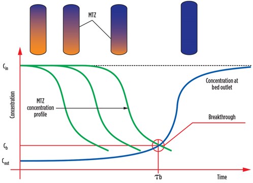 |
| FIG. 4. Adsorption process principles. |
As time passes, the mass transfer zone moves downward through the bed until it reaches the bottom of the column. At this point the entire bed has become water-saturated, and the adsorption process comes to an end. In time, the water dewpoint at the tower outlet draws an “S” curve, known as the breakthrough curve, represented by the blue line in FIG. 4.
When the water concentration at the bed outlet touches the (Cb, τb) point (the water dewpoint corresponding to the gas specification) on the breakthrough curve, the fixed bed is considered exhausted. It is then excluded from the production cycle and regenerated. In industrial practice, the end of the production cycle is not set by the analytical measurement of water dewpoint in the treated gas; rather, it is set by a predetermined time τ (estimated to be close to τb).
Activated alumina, silica gel and molecular sieves are the most-used sorbents for drying natural gas. Activated alumina is the least-expensive sorbent material for drying natural gas to –70°C. The major disadvantages of activated alumina are the coadsorption of hydrocarbons, which results in a reduced water load and loss of production, and the rehydration by contact with wet gas at high temperature during the regeneration stage. Silica gel features a high water adsorption capacity and can also adsorb C₅+ components, making it available for the simultaneous removal of water and gasoline from natural gas. The water dewpoint attainable with silica gel is around –55°C to –60°C.
Molecular sieves are synthetic zeolites (i.e., metal aluminosilicates) with three-dimensional crystalline structures containing interconnecting cavities of uniform size, separated by equally uniform, narrower openings. Molecular sieves can dry natural gas to a dewpoint lower than –100°C. For this reason, these materials are eligible for drying the raw gas intended for cryogenic hydrocarbon recovery applications.
A gas dehydration plant based on solid sorbent comprises at least two towers, one in adsorption mode and the other in regeneration mode. FIG. 5 shows a basic process scheme of a common gas dehydration unit based on the adsorption process. In this scheme, the adsorption circuit is highlighted by the green lines, the heating loop by the red lines and the cooling loop by the blue lines.
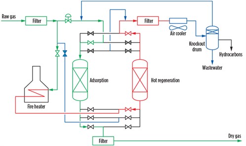 |
| FIG. 5. A typical adsorption process. |
Adsorption is a dynamic process involving batch-wise operations; the continuity of the entire system is ensured by the synchronicity of the columns. When one tower is in adsorption mode, the other is in regeneration mode. When the adsorption tower becomes exhausted, the previously regenerated tower can promptly enter the production cycle.
The adsorption process is favored by low temperature. After a bed has been heated, typically at 170°C–260°C, it is cooled to 30°C–40°C to make it fresh again. Therefore, a regeneration cycle includes both heating and cooling stages.
In the process arrangement shown in FIG. 5, a slipstream (typically 10%–20% of the raw gas) is used as regeneration gas. To create the driving force needed to circulate the gas through the regeneration loop, the regeneration gas is taken upstream of the control valve and reinjected into the adsorption circuit downstream of the control valve. The overall driving force for the regeneration gas circulation is provided by this control valve.
The major disadvantage of this process arrangement is the relatively high pressure drop between the raw gas and the dry gas, which requires an increasing energy consumption when the dry gas must be compressed. In such cases, the pressure drop can be minimized by inserting a recycle compressor in the regeneration loop, as illustrated in FIG. 6.
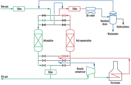 |
| FIG. 6. A low-pressure-drop adsorption process. |
In the process configuration shown in FIG. 6, the recycle compressor is fed with a slipstream of dry gas. In other configurations it recirculates the wet gas exiting the three-phase separator. Dry gas is more effective in removing water and does not partially rehydrate the bed during the cooling cycle.
In both FIG. 5 and FIG. 6, the regeneration gas is fed to the bottom of the tower during heating and cooling. Note: During the cooling cycle, the bottom part of the regenerated bed picks up a small quantity of water when wet gas is used as regeneration gas, as shown in FIG. 5. This water pickup does not take place when dry gas is used for the upflow regeneration pattern. In this case, the bottom of the bed is always contacted by dry gas, and the result is a more efficient regeneration step. A similar effect can be attained with the downward regeneration pattern, in which the regeneration gas flows from the top to the bottom of the tower.
Both process setups have filter systems. At the gas dehydration unit inlet, a filter is necessary to remove solid materials (piping scales and rust), along with the free water possibly entrained by the gas. The solid materials must be removed because they foul the sorbent bed, causing a higher pressure drop along the bed and even clogging. Free water must be removed by means of coalescer filters because it causes breaking and powdering of the sorbent.
Since each tower is subject to cyclic temperature swing, over time some sorbent beads crash, producing fines and powder. These solid materials can cause operational troubles in downstream processes and to the gas cooler of the regeneration loop. Therefore, mechanical filters must also be installed on the outlet sides of the gas dehydration unit and upstream of the gas cooler.
Finally, it is worth noting that the cycle length of an adsorption process is established on the basis of an operating labor schedule, resulting in usual 8-hr, 12-hr, 16-hr and 24-hr cycles. Shorter cycle lengths are more economical in terms of equipment sizing and desiccant charge; however, operating costs may be higher due to more frequent operation of valves and shorter desiccant life, which entails more frequent replacement. GP
NOTES
a Coldfinger process
b DRIZO process
c DRIGAS process
 |
LORENZO MICUCCI is a Senior Director at Siirtec Nigi SpA. He has more than 30 yr of experience in the engineering and contracting industry, most of which have been spent in the natural gas sector. In 2001, he joined Siirtec Nigi in Milan, where he directed the process design and operations department and the research and development department. During his time as R&D head, three patents have been granted to Siirtec Nigi, two of which have been implemented on an industrial scale. At present, he is the Senior Director of the technology and marketing departments. Mr. Micucci also worked for Saipem (Snamprogetti) as a Plant Designer for integrated gasification combined cycle and gas-to-liquids plants. He holds an MS degree in chemical engineering from the University of Bologna in Italy and is enrolled as a Qualified Engineer in the Register of Milan Order of Engineers.


Comments