
Process selection for deep COS removal from feed gas
A plan by Saudi Aramco to increase Saudi Arabia’s crude processing capacity includes grassroots facilities for processing approximately 2,500 MMsft3d of feed gas from various offshore fields. As part of this development, two NGL fractionation trains will be constructed to process propane plus (C3+) NGL feed streams and produce propane, butane and natural gasoline products that adhere to Saudi Aramco product specifications. At a later stage of the project, a higher content of carbonyl sulfide (COS) was found to be present in the feed gas. If left untreated, high COS in feed will cause the propane stream to fail product specification requirements.
This article discusses Saudi Aramco’s methodical approach to address this challenge during the design stage. It includes an analysis to shortlist the technologies available to remove COS and an explanation of the technology that provides the most optimum solution. This article also highlights key issues to be considered during the design stage and the technology selection approach to ensure that overall plant operability is not jeopardized.
Project scope. The NGL fractionation trains will receive a C3+ stream from the demethanizer bottoms and a C3+ stream from the condensate stripper bottoms feed from the plant. The NGL fractionation train will fractionate the C3+ NGL feeds into propane, butane, pentane, natural gasoline and color body products.
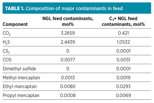
The composition of contaminants, particularly sulfur species for both feed streams, is summarized in Table 1. The simplified flow diagram for the NGL fractionation trains is shown in Fig. 1. The fractionated products will be stored onsite for domestic use or for export.
 |
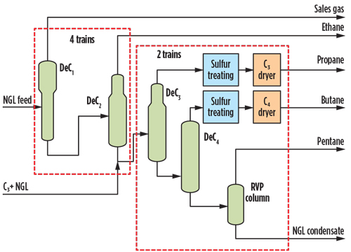 |
| Fig. 1. NGL fractionation simplified flow diagram. |
Propane and butane products are treated through a typical caustic-based process for mercaptans removal. The treated stream is then routed to a liquid dehydrator to meet a company water specification of 0.1 ppmv. Both treated liquid propane and butane products are then routed to their respective storage for either domestic consumption or export use.
One of the major challenges is the presence of COS that arrives in the feed fluids to the gas processing plant. COS contained in the inlet gas will tend to concentrate in the propane product stream. After fractionation of the treated gas, approximately 89% of the COS ends up in the C3 stream, while 5% and 6% remain in the C2 and treated gas fraction, respectively.1,2,3 The COS presence in the product could cause product off-specification problems in downstream units.
Propane product must meet Saudi Aramco product specifications SAPS-A-140 and SAPS-A-147:4,5
- 5-ppmw hydrogen sulfide (H2S)
- 30-ppmw total sulfur (as S)
- Copper strip test 1b (dark orange) for corrosive compounds.
Impact of COS on product specifications. COS by itself is not detectable in dry LPG product. Due to the hydrolysis of COS in the presence of water to form H2S and CO2, COS must be removed to maintain the product allowable corrosivity specifications. While COS is not a corrosive compound, its hydrolysis product, H2S, is corrosive, especially in the presence of water.
In addition to corrosion, hydrolysis of COS may act as a catalyst poison to downstream users. The LPG product can also fail the standard test for corrosivity, the copper strip corrosion test,6 upon retesting if the contaminated LPG comes into contact with air or water contaminants introduced at a later stage. It is, therefore, important to effectively remove COS from the product stream.
One article has indicated that a COS concentration of 58 ppm (mass/mass), presumably through COS hydrolysis, will cause failure of the copper strip corrosion test. Other researchers have challenged this threshold.7 It has also been reported that COS had no tarnish effect on copper up to a concentration of 20 ppmw, but a slight discoloration was observed at 100 ppmw.8 If COS is suspected, additional product testing9,10 and treatment are recommended to prevent the introduction of COS into the distribution system. Minimally, the COS concentration must be removed to meet the total sulfur content.
It is important to address any possible COS contamination during the early design stage to avoid late investment of a treatment system for a particular development.
COS treatment—literature review. COS can either be removed in the gas stream or the LPG product stream. COS present in the gas stream is typically removed through a potassium carbonate solution resulting from a hot potassium carbonate process for CO2 removal downstream of the steam reformer. COS can also be converted to H2S by hydrogenation or hydrolysis before H2S removal. This thermal and catalytic conversion is typically performed for coal gasification product gas.11 It is important to remove COS due to the risk of the hydrolysis reaction that can form H2S in the product.
It has been reported that COS can form through the conversion of H2S and CO2, in the absence of water, through an endothermic hydrolysis reaction in molecular sieve dehydration beds. The catalytic activity and structure of molecular sieves have a significant influence on COS formation in the presence of H2S and CO2.12,13 Therefore, it is indicated that the use of adsorbent materials for dehydration can be a major cause of COS formation. Theoretically, this suggests that residue H2S in the treated gas is converted to COS in the molecular sieve dehydration units on a mol-to-mol basis. The use of small-pore molecular sieves (e.g., 3A vs. 4A) is also suggested to avoid the reactions that form COS within the pores.14,15
For adsorbent treatment, the technology can be based on regenerable or non-regenerable processes. Due to the low polarity of COS, it cannot be adsorbed by most molecular sieve materials. Therefore, a chemically reactive adsorbent material that bonds in a nonreversible reaction with COS was used instead of molecular sieve materials for the adsorbent treatment.
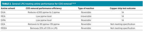
In the fractionation unit, the majority of the COS ends up in the propane stream.16 In the LPG product, COS can be removed through amine LPG treating and adsorbent treatment. Each amine has a different COS removal performance, depending on the thermodynamic reaction associated with the particular amine. The performance for each amine is tabulated in Table 2. It is reported that, even though MEA can reach the expected copper strip test outcome, MEA is not suitable since it is susceptible to degradation by COS.17 The MEA irreversible reaction has made DIPA and DGA the most preferred solvents for use in COS LPG treatment.
 |
The COS removal efficiency using amines can be enhanced by using formulated caustic wash (i.e., MEA added to the caustic) downstream of the amine/LPG treater. It is reported that an MEA concentration of at least approximately 1.5 wt% in the caustic can be used to achieve COS removal of less than 0.04 ppmw reported as S.11 The spent caustic with MEA presence will be exported for further treatment.
It is important to note that the polar compounds (e.g., H2O, CO2 and H2S) must be removed prior to COS removal in adsorbent beds.16 It is reported that if COS is the only contaminant present, then adsorbent treatment is the most economical process compared to amine processes.14
Other nonconventional processes have been developed based on the use of physical solvents and a hybrid of heterogeneous catalysis with amine treatment to remove COS from the gas stream.3 At present, not many plant references are available in literature on the use of the unconventional processes.
Study methodology. A step-by-step approach was developed to design the proper treatment for the LPG product:
- Process simulation to identify sulfur distribution
- Identification of COS removal options
- Selection of optimum solution.
Process simulation. It is important to understand the sulfur species distribution across the fractionation train. This will enable the process designer to determine the expected total sulfur content and accordingly identify the amount of COS required to be removed to meet the total sulfur specification.
Two proprietary simulation programs20,21 were used for comparison purposes. Distribution of the main sulfur contaminants (e.g., H2S, CS2, COS and light mercaptans) across the fractionation units was then compared between the two simulation programs.
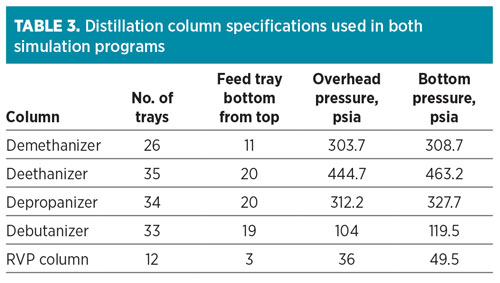
The sulfur-containing compounds in the NGL products were simulated using the software programs, based on the Peng–Robinson equation of state and respective software built-in binary interaction parameters. The column specifications used in the simulation are summarized in Table 3. Since the gas will be treated with a proprietary solvent at the acid gas removal unit, the simulations developed will be compared to sweet gas product, which has 6 ppmv of COS feeding the demethanizer.
 |
The results for the sulfur species distribution for the two programs with 6 ppmv in the demethanizer inlet feed are shown in Table 4 and Table 5, respectively. It is evident from both simulation programs that 80% of the CO2 is discharged with demethanizer overhead product, while approximately 99% of the H2S will typically flow with the ethane stream.
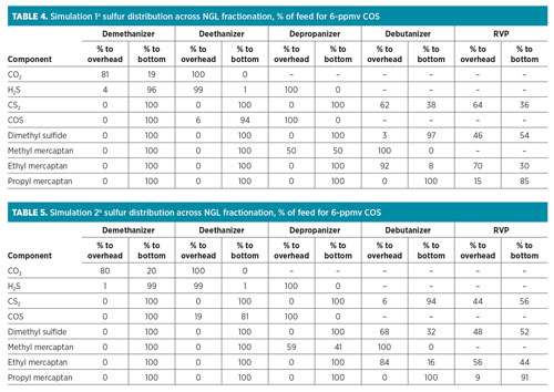 |
For COS, as per Simulation 1,a 6% of the content from the feed will be with the ethane product, while the remaining feed will flow with the propane stream. For Simulation 2,b the approximate amount of COS in the feed that will be with the ethane product was simulated as 19%, while the remaining will be with the propane product. The overall distributions across the NGL fractionation summary for both simulations are indicated in Fig. 2.
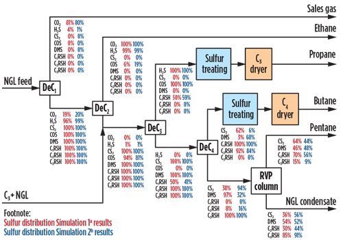 |
| Fig. 2. NGL fractionation simplified flow diagram for 6-ppmv COS in the inlet feed. |
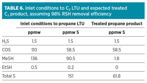
Based on the results, Simulation 1a provides a more conservative approach for the expected COS estimated composition in the propane product. Taking this into consideration, COS in the depropanizer overhead was estimated to be approximately 110 ppmw.
Assuming the propane product is treated with a conventional caustic wash process for its liquid treatment unit (LTU), the expected total sulfur content in the treated propane product is 61.8 ppmw (assuming 98% removal efficiency for mercaptans and no removal of H2S and COS as tabulated in Table 5). It was demonstrated that COS accounted for approximately 95% of the total sulfur content in the treated propane product. This concentration exceeded the maximum total sulfur specification of 30 ppmw. It is necessary to remove as much COS as possible to meet the total sulfur specification for the propane product stream.
 |
Identification of COS removal options. Several alternative options to caustic treatment were evaluated to manage the total sulfur concentration within the required specification by removing COS. The shortlisted options were:
- Option 1: Regenerable adsorption bed. One option is a regenerable adsorption bed, which uses a proprietary activated alumina. The process must operate with a dry feed, otherwise water would be preferentially adsorbed, leading to increased bed size. The unit is located downstream of the LPG product treating unit and dehydrators, as shown in Fig. 3.
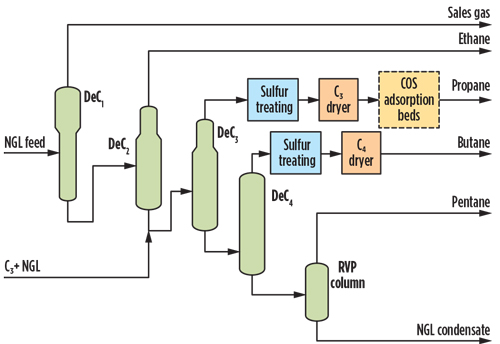
Fig. 3. Option 1 NGL fractionation simplified flow diagram with COS regenerable adsorption beds.
The main advantages are that the process is easy to operate, does not require licensed technology and can treat high COS levels to reach approximately 1 ppmw as S in the treated product. The disadvantages associated with this option are an expected large regenerable adsorption bed size, particularly if other contaminants are expected; high adsorbent materials cost; and challenges in integration of the regeneration system with the plant, particularly the discharge location for the spent regeneration gas. The options here are either to route it to a thermal oxidizer or to recompress and route it directly as sales gas if the total sulfur composition is not affected. - Option 2: MEA-enhanced caustic prewash. Caustic scrubbing is an effective technology for removing trace amounts of H2S and mercaptans. It is not effective in removing COS. The removal efficiency of COS in the caustic system can be enhanced using amines (i.e., MEA added to the caustic), as shown in Fig. 4. The enhanced caustic is installed upstream of the LTU to remove the COS prior to the main LTU process. A water wash is located downstream of the caustic wash to remove any dissolved or entrained salts.
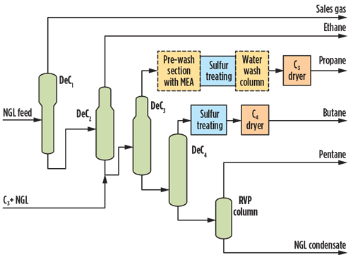
Fig. 4. Option 2 NGL fractionation simplified flow diagram with enhanced prewash.
The presence of a small MEA concentration allows the plant to achieve COS removal of less than 0.04 ppmw reported as S. At the expected COS concentration of 104 ppmw as S in the feed, it is understood from a potential licensor that treatment of up to 150 ppmw as S is feasible by modifying/adding some equipment in the licensed LTU process—i.e., by adding a small MEA concentration. Spent or diluted caustic is disposed of and replaced with fresh caustic to maintain removal efficiency. Above 170 ppmw, COS as S in the feed and large liquid effluent losses, including caustic, were considered unacceptable.
One of the major challenges with this option is the disposal handling. The disposal option could include an alternative third-party contractor offering a salt-tolerant incinerator and wet air oxidation. The use of MEA to enhance COS removal may complicate effluent treatment and increase associated costs. Therefore, pursuit of this option will require a reduction in the expected effluent flowrate to a more practical level.
- Option 3: LPG product amine/solvent treating. The only feasible absorption process for COS removal from liquid propane is to use a licensed amine solvent to reduce COS to within specification. This solvent is installed upstream of the propane liquid treatment unit, as shown in Fig. 5. Licensed solutions are available to reduce COS to a low enough concentration to meet the total sulfur concentration. Amines such as DIPA and accelerated MDEA are known to remove COS to low levels, but the performance can be guaranteed only in a licensed process.
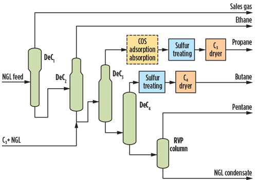
Fig. 5. Option 3 NGL fractionation simplified flow diagram with COS amine absorption.
The advantage of upstream amine treatment is that there is no impact on the LTU bidder selection process or licensor guarantees. Another advantage is its high efficiency, which avoids the need for other downstream treatment to remove COS in the liquid stream. The disadvantage is that this would need to be licensed, or a proprietary amine supply would be required to achieve the COS level provided to the LTU bidders, which adds to the expected higher CAPEX and OPEX costs.
As this is a regenerable process, the anticipated acid gas stream will need to be handled in the existing acid gas regeneration system if the same type of solvent is being used. The project schedule will be affected, since the amine selection is already completed without consideration for the high COS content, which was confirmed at a later stage of the project. - Option 4: Enhanced amine for acid gas removal (AGR). In a technical paper, the deep COS removal capabilities of accelerated MDEA formulated solvent were investigated. A strong correlation between the removal rate of CO2 and COS was demonstrated at a Canadian pilot plant. The results showed no COS removal for pure MDEA solvent at up to 80% CO2 removal. COS removal sharply increased as the 80% removal efficiency was exceeded, and it achieved almost complete removal when CO2 was completely absorbed.22
If this option is selected, the expected COS concentration using a licensed, tailor-made, accelerated MDEA solvent is estimated to be approximately 1 ppmv at the treated gas outlet. Consequently, at this concentration, the expected COS concentration in the propane product is reduced to approximately 34 ppmw, or 18 ppmw as S. Although it is below the total sulfur specification, this is still considered a tight margin from an operational perspective, especially in the case of a process upset in the AGR. The maximum COS concentration for the gas sweetening treated gas to reach 30 ppmw total sulfur specification in liquid propane is approximately 1.8 ppmv.
The required COS concentration to meet the total sulfur specification is very tight, which leaves no margin for the removal of mercaptans in the LTU. Therefore, additional measures must be considered to mitigate risk and ensure that the COS concentration is within a comfortable design margin, in case any process upsets are observed. - Option 5: Option 2 + 4 hybrid, enhanced amine for AGR with MEA caustic prewash. Although the enhanced AGR can reduce the COS content of the treated gas ex-AGR to less than 1 ppmv, there is still a risk of exceeding the COS content beyond 2 ppmv, which would result in the propane product total S being off-specification. As a solution to the risk identified in Option 4, additional measures must be considered to mitigate risk and ensure that the COS concentration is within a comfortable design margin, in case any process upsets are observed.
One option is to integrate Option 2 and Option 4, as shown in Fig. 6. This hybrid approach ensures that the polishing step is available if any diversion from specifications is observed, without the need to over-design the polishing system. Maximizing COS removal in the gas sweetening unit acts as the first step for COS treatment, which provides the C2+ NGL feed to the NGL fractionation train depropanizer. The reduction in COS to 1 ppmv, resulting from improved AGRU performance, enables a more feasible secondary polishing treatment option through an enhanced caustic wash system.
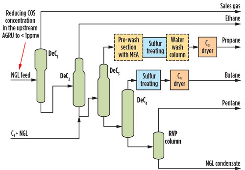
Fig. 6. Option 5, maximizing COS removal in the AGRU while polishing with enhanced caustic.
The effect of reducing COS from the AGRU and enhancing the caustic with the MEA addition allows potential licensors to meet the total sulfur specification while reducing the expected effluent rate. Considering that the H2S concentration would also be reduced by increasing the COS removal efficiency, the expected effluent rate (based on 25% removal of COS in prewash with enhanced caustic) is reduced by approximately 22% from the original value—i.e., 1,020 gal/d vs. 1,300 gal/d of effluent flow.
Installing enhanced caustic as the polishing step also allows for operational flexibility if COS hydrolysis occurs in downstream transmission systems. To completely eliminate the possibility of COS hydrolysis, COS removal to low levels (close to 100% removal) is recommended, which results in an increase of effluent flow by 33%—i.e., 1,770 gal/d vs. 1,300 gal/d. For all cases, a safe disposal location for the spent sulfidic caustic must be considered.
Selection of optimum solution. As identified at a later stage of the project, a higher content of COS will be present in the feed gas. The technology selected must result in the lowest impact to the project and process equipment without jeopardizing process specifications. A simplified technical matrix was developed to summarize the relative advantages and disadvantages of the various options, as shown in Table 7. Each option is compared against the relative consequences in terms of process scope, maintainability, project deliverability and complexity. At this stage, the cost impact is not included, as the primary focus is the schedule impact.
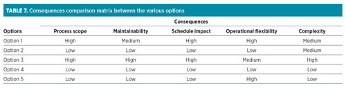 |
Most of the treatment options are without material consequence, in terms of both equipment addition/modification and operating/integration complexity. Treatment downstream of the LTU, as per Option 1, is not favored due to difficulties with licensor guarantees with respect to the measurement of COS into and out of the unit. Also, the size and cost of adsorption units, along with the potential disposal of regeneration gas, makes these options less attractive.
COS removed within the LTU (Option 2), through an enhanced caustic prewash system, appears to have the least impact on process equipment and operations. COS may also be removed by amine treatment, as per Option 3. Although it is simpler to remove COS in a liquid stream rather than a gas phase, a licensed solution at this stage of the project will have a significant impact on the schedule. Additionally, the handling of the acid gas ex-regenerator requires the stream to be routed to the sulfur recovery unit or flare gas recovery unit, which may affect the process sizing of the particular system. In the meantime, relying on COS removal to 1 ppmv, as per Option 4, poses a risk during operational upset, as the total sulfur specification of 30 ppmw may be exceeded.
Therefore, synergizing Option 2 and Option 4 with the reduction in COS—resulting from improved AGRU performance, as per Option 5—creates effluent levels comparable to previously bid values. Additionally, the solution can be designed so that it provides operational flexibility to reduce the effluent if COS can be removed to less than 1 ppmv in the gas sweetening unit. It can also increase the necessary caustic flow to ensure the complete removal of COS to avoid any hydrolysis occurring downstream. Option 5 provides a favorable technical solution that minimizes the impact on the project.
Takeaway. Determining the optimum technology to treat NGL products, particularly in the middle of a design stage, poses a challenging task for the responsible team. After understanding the mechanism principles that cause COS to affect product specifications, a step-by-step approach is necessary for designing the proper treatment.
The first step is to perform process simulation to identify sulfur distribution across the NGL products. It is clear from the literature review and from process simulation, using two simulation tools, that all the COS will end up in the propane stream. It is interesting to note that Simulation 1a provided a higher COS content in the propane stream than Simulation 2b—almost 13% higher. For conservative purposes, Simulation 1a estimates were used as the design basis. The comparison also provided an opportunity to verify which simulation tool gives a more accurate sulfur distribution across the NGL products, allowing further optimization of design.
In the second step, the various options to remove COS must be developed and shortlisted. Considering the stage of the project, only proven and less complex technologies should be selected. Finally, it is recognized that most of the treatment options are without material consequence, both in terms of equipment addition/modification and operating/integration complexity. Note: The technology selection is dependent on the feed contaminants, amount of sulfur, project stage and available systems at the facility. It is unique for each project. For all cases, it is important to know the scope of feed contaminants, including COS, as early as possible to avoid changes at a late stage of the project.
For this particular condition and at this stage of the project, the hybrid option is the most feasible approach. The hybrid approach consists of maximizing sulfur removal in the feed gas by selecting the proper gas sweetening solvent and enhancing sulfur treating units for the LPG product. The optimum solution was based on the technology with the least impact in terms of process equipment, operations and project delivery. This solution provided operational flexibility and did not jeopardize the process specifications. GP
Acknowledgments
The authors would like to thank various personnel within Saudi Aramco’s project management team that provided data related to COS treatment.
Notes
a HYSYS
b ProMax
Literature cited
- Moshfeghian, M., “Distribution of sulfur-containing compounds in NGL products,” PetroSkills, February 1, 2010, online: http://www.jmcampbell.com/tip-of-the-month/2010/02/distribution-of-sulfur-containing-compounds-in-ngl-products/
- Moshfeghian, M., “Distribution of sulfur-containing compounds in NGL products by three simulators,” PetroSkills, May 1, 2010, online: http://www.jmcampbell.com/tip-of-the-month/2010/05/distribution-of-sulfur-containing-compounds-in-ngl-products-by-three-simulators/
- Magné-Drisch, J., J. Gazarian, J. Gonnard, J.-M. Schweitzer, D. Chiche, et al., “COSWEETTM: A new process to reach very high COS specification on natural gas treatment combined with selective H2S removal,” Oil & Gas Science and Technology—Revue de IFP Energies nouvelles, Institut Français du Pétrole, 2016, Vol. 71, Iss. 3., May/June 2016.
- Saudi Aramco product specification SAPS-A-140, Saudi Arabian Oil Co., Dhahran, Saudi Arabia.
- Saudi Aramco product specification SAPS-A-147, Saudi Arabian Oil Co., Dhahran, Saudi Arabia.
- ASTM D1838-16, “Standard test method for copper strip corrosion by liquefied petroleum (LP) gases,” ASTM International, West Conshohocken, Pennsylvania, 2016.
- Andersen, W. C. et al., “The ASTM copper strip corrosion test: Application propane with carbonyl sulfide and hydrogen sulfide,” Energy & Fuels, 2004.
- Clark, P. D. and K. L. Lesage, “An examination of interfering factors in the ASTM D-1838 copper strip test,” GPA Research Project No. 982-2, March 2006.
- “Tentative method for the determination of carbonyl sulfide (COS) in un-odorized liquid propane,” GPA Standard No. 2290, 1990.
- UOP212-05, “Hydrogen sulfide, mercaptan sulfur, and carbonyl sulfide in hydrocarbon gases by potentiometric titration,” ASTM International, West Conshohocken, Pennsylvania, 2005.
- Kohl, A. and R. Nielsen, Gas Purification, 5th Ed., Gulf Publishing Company, Houston, Texas, 1997.
- Yan, T., C. Honggang and H. Jinlong, “Formation of carbonyl sulfide during molecular sieve dehydration process from high sour matural gas in China,” SPE 131908, International Oil & Gas Conference and Exhibition, Beijing, China, 2010.
- Bathen, D., V. Chowanietz and C. Pasel, “Formation of COS on different adsorbents in natural gas treatment plants,” Oil Gas European Magazine, Vol. 42, Iss. 2, June 2016.
- “Study compares COS-removal processes,” Oil & Gas Journal, September 22, 2003, online: https://www.ogj.com/articles/print/volume-101/issue-36/processing/study-compares-cos-removal-processes.html
- Rhinesmith, R. B., P. J. Archer and S. J. Watson, “Carbonyl sulfide (COS) removal from propane,” GPA Research Project No. 991, June 2001.
- Harrison, M. et al., “Achieving product specifications for ethane through to pentane plus from NGL fractionation plants,” Gastech, Bilbao, Spain, March 14–17, 2005.
- Little, R. J. et al., “Kinetics of COS with primary and secondary amines in aqueous solutions,” AIChE Journal, Vol. 38, Iss. 2, February 1992.
- Cantrell, J. et al., “Operational considerations of side reactions in gas sweetening systems,” Laurence Reid Gas Conditioning Conference, Norman, Oklahoma, February 26–March 1, 2017.
- Huttenhuis, P. J. G. et al., “Absorption of carbonyl sulphide in aqueous piperazine,” University of Twente, the Netherlands, IChemE Symposium, 2006.
- ASPEN HYSYS Version 9.0, Aspen Technology Inc., Cambridge, Massachusetts, 2016.
- ProMax 4.0, Bryan Research and Engineering Inc., Bryan, Texas, 2016.
- Katz, T. and V. Giesen, “The challenge of deep COS removal: Which options do we have,” BASF, GPA Europe, May 2009.
 |
Megat Ahmad Rithauddeen is a Process Engineering Specialist at Saudi Aramco. He joined the company in 2011 and is part of the Upstream Process Engineering Division, which provides engineering expertise in the processing of natural gas and light hydrocarbons. Prior to joining Saudi Aramco, he was a Process Specialist in the Process Optimization Engineering Unit of RasGas Ltd. in Qatar for 5 yr, and a Senior Process Engineer at Malaysia LNG for almost 7 yr. Mr. Rithauddeen has more than 20 yr of experience in the oil and gas industry in the Middle East and Malaysia, with a focus on gas processing, NGL and LNG. He is also an active member of two Saudi Aramco Standards committees—Oil & Gas Processing and Flow Assurance. Megat graduated in chemical engineering (with honors) from Monash University in Melbourne, Australia. He is also a chartered engineer, a member of the Institution of Chemical Engineers (IChemE) and a certified professional engineer with the Board of Engineers of Malaysia.
 |
Ahmad Fadzil is a Process Engineer at Saudi Aramco. He joined the company in 2013 and is part of the Upstream Process Engineering Division, which provides engineering expertise in the processing of natural gas and light hydrocarbons. Prior to joining Saudi Aramco, he was a Senior Process Engineer at Qatar Petroleum and at OGP Technical Services (a Petronas subsidiary). Mr. Fadzil has more than 23 yr of experience in the oil and gas industry in the Middle East and Malaysia, with focuses on gas production, gas processing, and NGL recovery and fractionation. He graduated in chemical engineering (with honors) from Universiti Teknologi in Malaysia. He is an associate member of IChemE.
 |
Eid Al-Helal is a Process Engineer at Saudi Aramco in the Process and Control Systems Department of the Upstream Process Engineering Division. He has also worked as an Operation Engineer in two operating facilities within Saudi Aramco—1 yr at the Waist gas plant and 2 yr at the Juaymah NGL fractionation plant. Mr. Helal earned a BS degree (with honors) in chemical engineering from Oregon State University. He is also a member of the American Institution of Chemical Engineering (AIChE) and the Society of Petroleum Engineers (SPE).
 |
Saud Al-Mudaibegh is a Process Engineering Specialist at Saudi Aramco. He joined the company in 1995 and is part of the Upstream Process Engineering Division. He worked at the Uthmaniyah gas plant for 3 yr as an operation engineer. He has 25 yr of experience in oil and gas processing, with focuses on gas sweetening, dehydration, NGL recovery, modular process unit design and fabrication. Mr. Mudaibegh holds a BS degree in chemical engineering from King Fahd University of Petroleum and Minerals in Dhahran, Saudi Arabia. He is also the Chairman of the Oil and Gas Process Engineering Committee at Saudi Aramco.


Comments