
Cost-effective, modular technologies for butane, propane and NGL treating
Hydrocarbon processing plants often encounter challenges with feedstocks containing high levels of mercaptans, which concentrate in hydrocarbon condensates and NGL when the mercaptans are not removed upstream by the acid gas removal unit (AGRU) or molecular sieve unit. While hydrogen sulfide (H2S), as well as carbon dioxide (CO2), are removed by amine treating units, most will remove little to no mercaptans. Only when physical solvents are used is removal possible.1,2
When NGL or condensates recovered in gas processing contain high levels of mercaptans, off-spec fractionated products can occur, the hydrocarbon can have negative odors and the value of the hydrocarbon can be decreased, resulting in loss of revenue. Additionally, the NGL, condensate or its fractionated products often will not meet total sulfur or will fail a quality test, such as a copper strip corrosion test.
The two most commonly used technologies for mercaptans removal are UOP’s Merox and Merichem’s Thiolex systems. UOP’s Merox process utilizes a proprietary catalyst, known simply as the Merox catalyst, along with heat and air to oxidize mercaptans to a disulfide in the regeneration stage.
The Merox process is a demonstrated and proven process for mercaptans removal. However, the large capital expense for these systems typically makes them viable only for large-scale applications. The Merox process is generally used for large-scale applications where caustic regeneration is required to make the operating economics viable. In addition, as part of the Merox process, a waste liquid stream (dimethyl disulfide) is formed after caustic regeneration. Therefore, provisions must be taken for its proper disposal or reprocessing.
Merichem’s Thiolex process utilizes a chemical mechanism similar to the UOP Merox process, with caustic extraction and regeneration via a catalytic oxidation stage to separate, transform and remove mercaptans. It also has a liquid waste stream (dimethyl disulfide) that must be disposed of. This process system carries high capital expenses, similar to the UOP Merox system. Both systems are also subject to caustic waste disposal, and many systems use a bleed and feed of fresh caustic to maintain a high pH.
Due to limited technologies to cost-effectively treat hydrocarbon streams containing low-tonnage mercaptans and H2S, one companya set a goal to develop a small and flexible system to address those needs. As an alternative for large-scale systems, this company has developed a systemb that is specifically designed to treat hydrocarbon streams with less than 1 tpd of mercaptans. These systems can be skid-mounted, are compact and require a minimal footprint. The technology has a chemical injection stage, followed by a proprietary contacting and separation process. The proprietary chemical converts H2S, carbonyl sulfide (COS) and mercaptans into stable, non-hazardous and water-soluble compounds. The spent chemical is stable and easily disposed of by any of several methods, depending on the plant infrastructure.
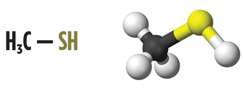
H2S, mercaptans and mercaptans removal. Mercaptans, or thiols, are a group of sulfur-based components that are found in many hydrocarbon streams, mainly as an impurity. Mercaptans are similar to alcohols, but with the oxygen atom replaced by a sulfur atom. This change confers to mercaptan molecules distinct chemical and physical properties. Organoleptic properties are also affected; for example, mercaptans have a particularly foul odor. The change from a more electronegative atom (oxygen) to sulfur also imparts to mercaptans a more acidic character compared to their alcohol counterparts due to the sulfur atom’s stabilizing effect. Mercaptans, however, are only slightly acidic, and this acidity is reduced as the molecular weight of the mercaptan increases. Fig. 1 shows the molecular formula and structural 3D model for one of the most common mercaptan contaminants, methyl mercaptan (also named methylthiol or methanethiol).
Relative to alcohols, mercaptans are more acidic. Butyl mercaptan has a pKa of 10.5 compared to 15 for butanol. Phenol mercaptan has a pKa of 6 compared to 10 for phenol. Therefore, mercaptanate (or thiolate) salts can be created by treating mercaptans with alkali hydroxides, such as sodium hydroxide or caustic. In fact, caustic is a common removal method for mercaptans in liquid streams (water and hydrocarbons). The chemical equations for the reaction of mercaptans (R-SH) and alcohols (R-OH) with sodium hydroxide are indicated in Eqs. 1 and 2:
R-SH + NaOH → NaS-R + H2O
(Forward reaction) (1)
R-OH + NaOH } NaO-R + H2O
(Equilibrium reaction) (2)
In addition, mercaptans have weaker intermolecular forces. They show little association by hydrogen bonding with water molecules or among themselves. Mercaptans have lower boiling points and are less soluble in water and other polar solvents than alcohols of similar molecular weight. Mercaptans will hence have a higher-equilibrium vapor pressure and will be more soluble in hydrocarbon phases.
 |
| Fig. 1. Molecular structure (left) and molecular model (right) of methyl mercaptan. |
Some mercaptans are also gaseous at ambient conditions in comparison to their oxygen analogues, due to their lower boiling point. One example is methyl mercaptan (gas) in comparison to methanol (liquid). The electronic configuration of mercaptans (namely the presence of d-orbitals in sulfur atoms) provides them with highly interactive properties with many surfaces (especially metals). This interaction is the basis of some of the common metal surface friction reducers. Sulfur molecules can also serve in many instances as metal ion chelants and metal stabilizers.
From health, safety and process perspectives, the removal of mercaptans is often necessary. Some mercaptans present strong odors and can cause serious disruptions to daily life. In fact, humans are highly sensitive to mercaptans at very low levels. For this reason, mercaptans are used as odorizers in consumer and commercial natural gas to alert to gas leaks. Some mercaptans can cause corrosion, and often lead to copper strip test failures under certain conditions. Mercaptans can negatively affect catalysis and solid adsorption beds, such as silica gel or alumina, by competing for access to the same active sites.
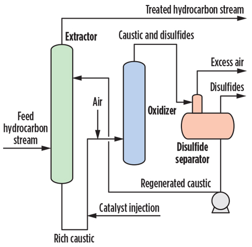 |
| Fig. 2. General regenerative caustic mercaptans removal process. |
Mercaptans removal is also necessary for reducing sulfur emissions, as combustion and emissions of mercaptans-containing compounds will lead to SOx formation. Mercaptans removal can be accomplished by a number of methods. The most common method utilized today is the reaction with caustic (sodium hydroxide), shown earlier. Oxidation by a strong oxidant reagent (such as sodium hypochlorite, oxygen and hydrogen peroxide, among others) has also been used. The chemical reactions for mercaptans oxidation are indicated in Eqs. 3 and 4:
2 R-SH + ½ O2 → R-S-S-R + H2O
(Oxidation by oxygen) (3)
R-SH + 3 H2O2 → R-SO3H
+ 3 H2O (Oxidation (4)
by hydrogen peroxide)
Other methods for mercaptans removal from hydrocarbon streams are available, including oxidation using ozone, biological removal processes, catalytic decomposition, adsorption into solid beds (i.e., functionalized activated carbon) and specialized solvents. However, only the latter two methods are commonly used in the industry. The use of sodium hydroxide for mercaptans removal is perhaps the most common worldwide.
The reaction with caustic is effective, but is also a reversible equilibrium. Sodium hydroxide is readily available at low cost. Non-regenerative caustic treatment produces a spent caustic stream that must be treated or managed properly. Regenerative caustic treatment produces disulfide oil and a waste caustic bleed. Fig. 2 shows a typical regenerative caustic mercaptans removal process.
The use of caustic for mercaptans removal causes high salt content. In many cases, an odor release occurs. In some cases, the spent or rich caustic can be regenerated using a catalytic process and oxygen. The oxygen regenerates the rich caustic so that it can be reused in the process; however, it also produces a secondary disulfide oil (DSO) byproduct. Disulfides (also called red oil) are water-immiscible materials that can be a challenge for disposal in a gas plant. The chemical reactions for the regenerative caustic removal of mercaptans are indicated in Eqs. 5 and 6:
2 R-SH + 2 NaOH → 2 NaS-R +
2 H2O (Extractor reaction (5)
with excess NaOH)
4 NaS-R + O2 + 2 H2O →
2 R-S-S-R (water immiscible
DSO) + 4 Na+ + 4 OH– (6)
(Regeneration)
where R = hydrocarbon group.
Alternative products were developed especially for mercaptans removal. The concept was to use a nonregenerative mercaptans removal method where the waste or byproduct can be easily treated at low cost. This not only minimizes capital costs but also reduces any post-treatment costs. The reaction pathway does not involve the use of caustic and eliminates the need for secondary treatments, such as regeneration of spent caustic or spent caustic disposal. The chemicalc is a specialized polyhydric alcohol molecule, stabilized by hydroxyl materials, that enables the removal of H2S, mercaptans and COS. The general chemical equation for the reaction with mercaptans is shown in Eq. 7:
R-SH + CA → R-S-S-R +
R-S-SO-R + R-R + SO4–2 + (7)
H2O (Oxidative coupling)
where R-S-SO-R = sulfoxide species (water soluble and does not affect the process).
The reactions show that water, sulfate (SO4–2) and other oxidized components are products of the reaction. The water-soluble sulfate ion is removed from the condensate in the aqueous chemical phase. The chemical additive (CA) is designed for use with process equipment, such as a phase separator downstream of the injection point. The challenge was to create a specialized system to operate with high efficiency and impart flexibility for its use. The developed systemb has a low capital cost relative to other mercaptans removal units in the industry today. The system also has a much smaller footprint, shorter delivery times and can be designed as a modular system, if necessary. The process can provide total filtration of the liquid hydrocarbon to be treated to protect the contactor from fouling. A chemical injection point was established for the chemistry, followed by a mixing and contacting stage for mass transfer and for enabling the reaction to occur more effectively. The system is also highly effective for treating the liquid hydrocarbon, as well as for removing water emulsions and water-soluble impurities.
System validation protocols. A gas plant near Alberta, Canada was selected to validate the technologyb. The plant required a cost-effective solution for the removal of low-molecular-weight mercaptans (C1–C3) present in a stabilized condensate stream. The facility was required to meet a mercaptans specifications for condensate below 175 mg/kg to meet a future pipeline specification. The average levels of C1–C3 mercaptans did not, however, meet the required specifications.
To determine if the devised system was feasible for mercaptans removal, an onsite test was performed using a miniaturized unit. The unit was designed to test any liquid hydrocarbon stream up to 5 gpm. This article outlines the field validation protocols and performance results for mercaptans removal in a hydrocarbon condensate stream. The onsite processing of a stabilized condensate slipstream, using a miniaturized unit, along with the injection of a proprietary chemicalc to remove the mercaptans, followed by a water wash stage, is shown in Fig. 3.
 |
| Fig. 3. Miniaturized systemb used for mercaptans removal validation. |
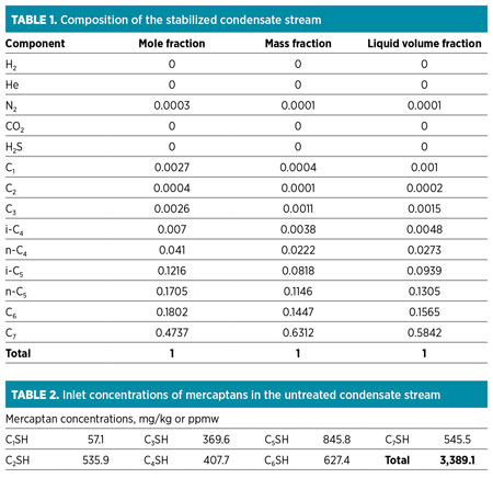
The stabilized condensate composition at the site is shown in Table 1. The inlet concentrations of mercaptans are presented in Table 2. The flow, temperature and pressure of the condensate stream at the moment of the system onsite validation were nearly 2,000 bpd, approximately 270°F and approximately 100 psig, respectively.
 |
The selected slipstream point for the condensate was located at the outlet of the stabilizer unit prior to cooling and at high temperature. The miniaturized system was assembled, using the same treatment configuration as a full-size system. Fig. 4 shows the schematic of the miniaturized system, including the injection points for the chemical and water, valve arrangement, contactor/extractor, water wash and effluent streams. The schematic in Fig. 4 is consistent with the image shown in Fig. 3.
The materials used for the onsite validation test included the miniaturized system, stainless steel tubing for connecting to the process, the proprietary chemicalc, reverse-osmosis-quality water, condensate sampling cylinders and a gas chromatograph equipped for mercaptans detection and quantification. Condensate sampling was done upstream and downstream of the system, as shown in Fig. 4.
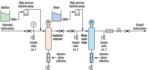 |
| Fig. 4. Schematic of the miniaturized systemb for field deployment and testing. |
Test conditions and procedures. The temperature of the condensate was approximately 300°F as measured at the stabilizer outlet, and a slipstream flowrate of 1 gpm–1.7 gpm of condensate was maintained from the stabilizer outlet into the system. The testing setpoints used were varied during testing to optimize the mercaptans removal efficiency. A 65-ml/min injection rate (chemical/water), or approximately 1%–1.7% of the total condensate flow treated, was generally used. The chemical/water injection was at room temperature (21°C). Samples were taken at the inlet and outlet of the system for analysis, using specialized cylinders to maintain sample integrity.
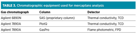
All mercaptans analysis was performed onsite. A 10-min run time after chemical injection was initiated was allowed before sampling for each data point. Local reverse osmosis water was used to dilute the chemicalc formulation for injection. The method for analyzing mercaptans was performed using a gas chromatograph and by introducing calibration samples for proper reference. A calibration curve was constructed for every mercaptan analyzed. The results were initially obtained in ppm on a volume basis and then further converted to ppmw. Table 3 presents the various chromatographic equipment used in the quantification of mercaptans.
 |
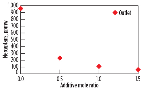
Mercaptans removal performance. The data for the accumulated mercaptans concentration were plotted as a function of the additive injection concentration in Fig. 5. The plots reflect the concentration at the outlet of the extractor (downstream of the water injection). The removal rates of C1–C3 mercaptans were plotted, as these were the mercaptans of significance for the pipeline specification. The Fig. 5 y axis shows the removal of mercaptans as a function of the chemical additive concentration in the mole ratio. Mole ratios of 0.5, 1 and 1.5 moles of active chemical per mole of total mercaptans were injected during sampling events, equivalent to 3,000, 4,500 and 6,000 ppmw, respectively, of the condensate stream.
 |
| Fig. 5. Removal of mercaptans at the outlet as a function of the chemical additive concentration, mol/mol. |
The chemical additivec significantly reduces the mercaptan levels in the condensate stream. The removal increases as the concentration of additive increases. The test protocol using the miniaturized system indicates that a 1 mole ratio is sufficient to lower the C1–C3 mercaptans levels to below 200 ppmw. Mercaptans levels are lowered more effectively for C1–C3 mercaptans, as the smaller-size mercaptans react faster with the chemical additive (reaction kinetics or by better molecular diffusion and mixing). It is, therefore, conceivable that the chemical injection concentration and injection rates can be optimized with the objective to remove certain mercaptans at target levels.
Residual water analysis. The injected water used was from a reverse-osmosis plant installed at the facility. The effluent-injected water from the miniaturized system was collected and further analyzed for common anions and cations. The water analysis was performed using an ion chromatography (IC) apparatus. Table 4 shows the results for the water analysis (for a 1-mole ratio additive injection).
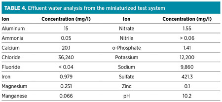 |
It can be observed from analysis that the effluent water had increased salt contents in terms of chlorides and sodium, which is typically found in natural formation waters (also known as connate water). In addition, the presence of calcium, magnesium, phosphate and nitrate is indicative of components present in produced water. The only two components originating from the chemical additive are sulfate and potassium. These components are generally simple to dispose of, as they are also present in natural waters. The presence of iron was interpreted as being from the naturally occurring water formation or as a byproduct of pipeline corrosion.
Scale-up considerations. The condensate stream presented high solids content and fouled the miniaturized system contactor/extractor more rapidly than anticipated. This aspect should be verified in any future condensate treating application to allow for proper feed conditioning, when necessary.
A number of aspects were deemed worth indicating. Operationally, it is important to mention that the chemistry performed effectively for mercaptans removal to the required levels. The results were further validated by independent onsite mercaptans testing, using specialized sampling cylinders and chromatographic techniques. Other important areas to consider are:
- The best chemical additivec dosage is between 1 mole and 1.5 mole ratio (for the application tested)
- Higher temperatures are beneficial for faster chemical reaction rates
- Condensate filtration upstream of the chemical injection is needed to protect the system from a high level of suspended particulates
- Lower-molecular-weight mercaptans are more effectively removed
- Sampling cylinders are critical for condensate sampling to maintain sample integrity, if testing low-boiling-point contaminants.
Full-scale systems. After the testing and validation work was completed as described, a full-scale systemb was designed, fabricated and installed. That system is shown under construction in Fig. 6.
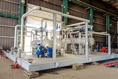 |
| Fig. 6. Full-scale systemb for condensate treating. |
The full-scale system was designed to process flowrates up to 12,000 bpd, with inlet mercaptan levels of up to 644 ppmw and 20 ppmw of H2S intermittently. The process guarantee was to treat the condensate to a level of 175 ppmw of C1–C3 mercaptans.
In October 2018, the system underwent commissioning and startup. During the startup phase, the operation was tuned for optimal performance and to execute the process guarantee. The condensate feed contained mercaptan levels from 413 ppmw–436 ppmw. The treated effluent was 88 ppmw and 119 ppmw, respectively, for the associated inlets. The chemical treatment was adjusted to target 150 ppmw to allow for variations in the feed.
Full-scale butane system. Another treatment skid was installed at a fractionation plant that was experiencing quality issues with its butane. The butane stream was required to pass specifications for hydrocarbon corrosion measured by the copper strip test. As done previously with the condensate application, a field trial was conducted with a miniature system to prove that the process could treat the butane to the plant’s quality specifications.
The stream showed the presence of several sulfur-based contaminants, such as mercaptans, sulfides, disulfides and sometimes H2S. The design flowrate of butane was 1,750 bpd, with an average operational rate of 1,000 bpd. The sulfur-based contaminants varied in concentration from 10 ppmw–100 ppmw. The system shown in Fig. 7 is the skid system installed for the butane.
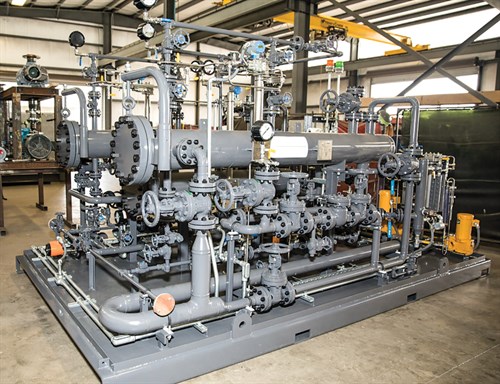 |
| Fig. 7. Full-scale systemb for butane treating. |
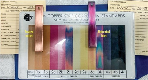
The treatment effect of the system for the butane is shown in Fig. 8. In this case, the butane production (feed butane to the system) yielded a copper strip test result of 3b. The reddish color of the copper surface can be observed against the ASTM copper strip test standard background. After treatment with the system, the copper strip test results were consistently 1a or 1b. The system was capable of treating the butane stream with different levels of copper strip tests results (4, 3 or 2) and consistently providing 1 results.
 |
|
Fig. 8. Copper strip test results when using the systemb for butane treating. The untreated copper strip test (3b result) is shown at right, and the treated copper strip test result (1b) is shown at left. |
In addition to passing the copper strip tests, the process can reduce the mercaptans in the butane to very low levels. While low levels of mercaptans were not originally part of the treatment design specification, the facility asked if a 5-ppmw level of combined methyl and ethyl mercaptan could be obtained. The chemicalc was reformulated and tested at the full-scale unit. New chemistries were trialed over several weeks in June 2019, with samples collected at the inlet and outlet.
The samples were analyzed using a gas chromatograph with a sulfur chemiluminescence detector set up for liquid injection. One chemistryd proved to be the best treatment for achieving low effluent mercaptan levels. This chemistry showed that, upon spikes of the methyl and ethyl mercaptans, the required 5-ppm specification could still be achieved. The results are shown in Table 5. GP
Notes
a Exion Systems
b Exion LT
c Exion LT-200
d Exion LT A-700
References
- Stewart, M. and K. Arnold, Gas Sweetening and Processing Field Manual, 1st Ed., Elsevier, October 2011.
- Kohl, A. L. and R. Nielsen, Gas Purification, 5th Ed., Gulf Publishing, Houston, Texas, September 1997.
 |
David Engel has more than 25 yr of industrial experience in a variety of chemical engineering and chemistry areas. He is the inventor in 22 US patents and the author of a number of technical and scientific papers. Dr. Engel has developed business and technology for Eastman Kodak, Eli Lilly, Pentair, General Electric and Sulphur Experts worldwide. He has specialized in chemical engineering, process chemistry, optimization and contaminant removal technologies. Dr. Engel is the Managing Director of Nexo Solutions and the Technology Leader for Exion Systems. He holds a BS degree in industrial chemistry, an MS degree in chemistry and a PhD in organic chemistry. He is also Six Sigma and Project Management certified. Dr. Engel is President of the American Filtration Society, Southwest Region; and a member of the Gas Processors Association Technical Section M, in addition to a member of the boards of directors at several companies.
 |
Scott Williams is a Process Engineer at Amine Optimization. He has industry experience in a number of projects in oil and gas, petrochemical, chemical and water treatment applications. As part of the Amine Optimization engineering group, Mr. Williams is responsible for technical design and solutions development in engineering and technology applications. He also provides support for analytical and specialized service projects. His recent work has been focused on amine unit contamination control, process stability and energy reduction. Mr. Williams holds a BS degree in chemical and biological engineering from the University of Colorado at Boulder.
 |
Heath Burns is an Engineer and General Manager of Exion Systems LLC. He has been working in the oil and gas and process industries for 20 yr. Mr. Burns' experience includes manufacturing, research and development, pilot testing, engineering design and business development.
He has extensive field experience in developing methods for analyzing, troubleshooting and mitigating various process contamination issues. He also consults for Nexo Solutions and Amine Optimization. Mr. Burns holds a BS degree in Mechanical Engineering Technology from Texas A&M University.
 |
Ryan Crowe is the Vice President of Business Development for Exion Systems LLC. He started as a futures trader on the Sydney Futures Exchange, where his success led him to a position with Chemical Bank in London. Mr. Crowe's sales and trading experience eventually led him to Singapore, where he transitioned to oil and gas and formed No Heat Resources, a chemical treating company. Mr. Crowe's experience in sulfur treating later prompted him to relocate to Texas, where he helped form Exion Systems. Mr. Crowe is also Managing Director of NH Resources. He holds a BS degree in commerce from the University of Canberra in Australia.


Comments