
Dual-methane expander liquefaction reduces LNG costs and complexity
G. W. Howe, G. F. Skinner and A. D. Maunder, Gasconsult Ltd., London, UK
LNG producers have sought to enhance project returns through higher plant capacities to achieve economies of scale. Many complex multi-refrigerant plants were constructed to realize this objective. However, the unprecedented capital costs and financial risks associated with these mega-scale plants may be unsustainable in an era of distressed energy prices. Some operators are looking for more flexible project development and commercial models that alleviate risk; they are seeking means to monetize smaller gas reserves with lower-cost schemes.
Dual-methane (DM) expandera liquefaction offers a differentiated solution for mid-scale and floating LNG (FLNG) applications. Unlike conventional processes, it uses no external refrigerants, utilizing instead natural gas feed as the refrigerant medium in an optimized system of expanders. This setup eliminates refrigerant storage and transfer systems used in MR cycles, as well as the additional process equipment used to extract refrigerant components from the feed gas. Makeup refrigerant is low-cost natural gas, as opposed to nitrogen or a mixture of hydrocarbons, thereby avoiding complex supply logistics and reducing operating costs.
The absence of liquid hydrocarbon refrigerant also makes for safer operations. The methane process requires significantly less power than other “safe” systems, such as multiple-expander nitrogen processes, allowing reduced capital cost through lower installed compressor power or increased LNG production from a selected compressor driver.
Single-train capacities exceeding 2 MMtpy are possible, facilitating phased project development and lower initial capital requirements, yet still allowing a progressive buildout of significant LNG capacity. The avoidance of equipment to produce, handle, store and process external refrigerants reduces cost, weight and footprint, making the technology particularly attractive for FLNG schemes. Where appropriate, freed-up deck space could be used to install additional productive liquefaction capacity, which would enhance project returns.
A number of variants of the basic configuration have also been developed for low-pressure (LP) feeds, the removal of heavy hydrocarbons and to facilitate benefits from high-speed (HS) compression. These variants further differentiate the technology and are described in this work.
 |
|
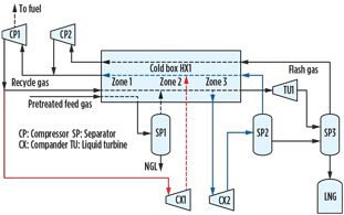
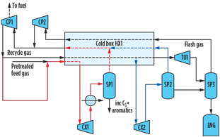
Fig. 1. Simplified schematic of proprietary DM expander process. |
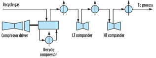
Process configuration. A simplified schematic of a proprietary DM expander process is shown in Fig. 1. Refrigeration is effected in two expander circuits, a warm circuit indicated in red and a low-temperature circuit shown in blue. Chilled gases from expanders CX1 and CX2 are routed to the cold box for cooling duty, and then returned to the expanders by the recycle compressor CP1. Flash gas is also routed through the cold box for cooling duty and recaptured to the system by a small compressor, CP2, which feeds the suction of the recycle compressor. The expanders are configured as companders and operate in series with the recycle gas compressor (Fig. 2), providing approximately 35% of the total compression power.
 |
|
Fig. 2. The expanders operate in series with the recycle gas |
The methane cycle is similar in concept to nitrogen expander schemes. However, it enjoys a fundamental advantage, as methane has a higher specific heat than nitrogen. This factor significantly reduces circulating gas flows, which, in turn, reduces power consumption and pipe sizes.
A patented feature of the described process is that partial liquefaction takes place in the low-temperature expander CX2—this efficiently converts latent heat directly into mechanical work and also permits a reduction in heat-transfer area and cost of the main heat exchanger HX1. An optional liquid turbine, TU1, in the LNG rundown line also improves efficiency by providing a significant chilling effect.
These features, together with the optimized distribution of flows, temperatures and pressures in the expander circuits, makes for a highly energy-efficient system consuming approximately 300 kWh/metric t of LNG in temperate climates. This performance is equivalent or better than that involving single-mixed-refrigerant (SMR) processes, and 15%–30% lower than the more sophisticated variants of dual- and triple-expander nitrogen schemes.
Alternative configurations. A number of variants of the technology have been investigated. These variants have the potential to further reduce capital cost and/or increase operating efficiency. Open methane cycles lend themselves to advantageous configurations for LP feed gases, removal of heavy hydrocarbons and HS rotating equipment.
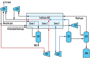
IPL for LP feed gases. All liquefaction technologies consume more power at lower feed gas pressures. The integrated pressure liquefaction (IPL) variant (Fig. 3) of the described process boosts LP feed gas by routing it after liquids separation in SP1 back to an interstage suction point on the recycle gas compressor, instead of to Zones 2 and 3 of the liquefaction section of the cold box, as shown in Fig. 1. This process provides a higher inlet pressure to the cold box independent of the feed gas pressure, enhancing liquefaction efficiency without the need for a separate feed gas compression plant.
 |
|
Fig. 3. The IPL variant boosts LP feed gas by routing it after |
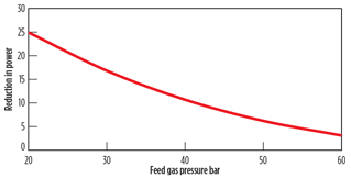
For 40°C ambient conditions on 25-bar pipeline gas (as might prevail, for instance, in the US Gulf Coast region), IPL operation at 80 bar achieves a reduction in power demand exceeding 20% of that for the basic DM expander system (Fig. 4). This capability is only available to open methane cycles. Nitrogen or SMR schemes require an additional compression facility to enhance liquefaction cycle efficiency; unlike open methane cycles, they do not have a methane compressor in their basic configuration.
 |
|
Fig. 4. IPL operation at 80 bar achieves a reduction in power |
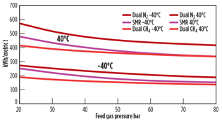
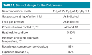
Fig. 5 provides the authors’ computations of the relative power demand measured in kWh/metric t of the DM (in IPL mode), SMR and dual-nitrogen processes over a pressure range of 20 bar–80 bar. This data is based on normalized machine efficiencies and provides an indication of the relative merits of the technologies in a warm climate and feed gas precooled scenarios (40°C and –40°C “cooled to” temperatures, respectively). The DM process is advantaged over the full data range. The Fig. 5 data assumes the design basis provided
in Table 1.
 |
|
Fig. 5. Computations of the relative power demand of the |
Integrated heavies removal (IHR). With heavier feed gases above or close to their critical pressures, adequate removal of C5+ and aromatics may require an upstream NGL unit. Typically, this expands the feed gas to a sub-critical pressure, condenses the heavy material and then recompresses the depleted gas for liquefaction.
In its IHR variant, the described DM cycle process removes heavy components by passing the feed gas and recycle gas through the warm circuit gas expander CX1 (Fig. 6), and separates the condensed heavy material from the expander outlet at subcritical pressure, around 10 bar–15 bar.
 |
|
Fig. 6. In its IHR variant, the DM cycle process removes heavy |
This solution decouples the vapor/liquid separation and feed gas pressures and saves a large part of the equipment and cost of a separate expander-based NGL removal unit. Specifically, the compander (CX1), recompression facilities (CP1) and associated bulk materials already exist in the basic DM configuration, avoiding additional capital cost. Weight and footprint are also reduced, which is particularly relevant to FLNG schemes.
High-speed compression. Methane can be compressed at a significantly higher rotational speed than the higher-molecular-weight hydrocarbons found in mixed refrigerant cycles. This permits the use of HS driver/compressor combinations that are significantly lower in cost and weight than those used in conventional processes.
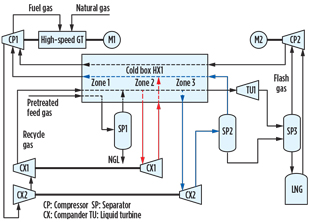
In a recent study conducted around an HS 46-MW output gas turbine (Fig. 7), the main recycle compressor is direct-driven and runs at a much higher speed (6,600 rpm) than conventional MR compressors. Since the turbine is a single-shaft machine, a small starter/helper electric motor, M1, is provided.
 |
|
Fig. 7. In an HS 46-MW output gas turbine, the main recycle |
The study, developed with support from the OEM, demonstrated an ability to achieve a capacity of 1.5 MMtpy/train with a power demand of approximately 310 kWh/t of LNG, based on a feed gas pressure of 60 bar, ambient air temperature of 30°C and seawater temperature of 23°C. Significant weight savings (> 70 metric t) for the gas turbine and the recycle compressor were demonstrated compared to a typical aero-derivative based solution, with cost savings for this equipment measured at 20%–30%. Although the gas turbine subject of the study was an industrial machine, the changeout capability at 48 hr is comparable to aero-derivative machines. The turbine also has longer equivalent operating hours (60,000 hr) between major overhauls than aero-derivatives. The energy efficiency at > 38% was respectable, with DLE < 15 ppm NOx.
Technology advantages. In addition to its low power demand, reduced equipment count and low footprint, a further set of advantages accrue to methane cycles from the absence of external refrigerants. Many of these advantages have particular relevance for FLNG schemes, where weight, deck space, operational simplicity and safety are important factors:
- No refrigerant logistics issues are present in remote or offshore locations. Neither shipments of light and heavy hydrocarbons, nor segregated storage to facilitate blending a mixed refrigerant, are required.
- Absolute security of refrigerant supply is ensured.
- No propane or other liquid hydrocarbon refrigerants are present, which offers a major safety advantage relative to MR schemes.
- Single-phase refrigerant (always a gas) makes the system motion-tolerant.
- Operational benefits relative to MR schemes are present. These benefits include no refrigerant makeup cost, no refrigerant composition adjustments to maintain cycle efficiency, shorter startup time from warm condition and reduced flaring.
Project returns. Most liquefaction schemes are built around a preselected compressor driver. An economically matched set of ancillary process equipment is assembled around this driver. Once the compressor driver is selected, the power available for liquefaction is set. Then, the overwhelmingly dominant factor determining LNG production is the liquefaction cycle efficiency. For mid-scale projects, the differential can run to some hundreds of millions of dollars, as measured by NPV.
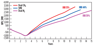
Fig. 8, developed by the authors from a case study, plots cumulative NPV vs. time for the DM cycle, a dual-nitrogen cycle and a basic SMR scheme for a nominal, 4-metric-MMtpy, five-train FLNG project monetizing a 2-Tcf gas field. The DM cycle earns higher returns over a shorter period of time because its superior efficiency supports a higher production capacity.
 |
|
Fig. 8. Cumulative NPV vs. time for the DM cycle, a dual- |
Technical validation. All equipment in the methane cycle process is fully proven in operation, and the process steps are well established in dozens of cryogenic gas processing plants. BP and three engineering companies (under nondisclosure agreements) have reviewed the described design, from simulations through key process and detailed design parameters.
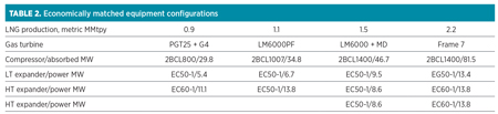
All of the companies confirmed the energy efficiency and key performance parameters. Leading equipment vendors have confirmed the mechanical design/configuration viability and that all equipment operates within a window of proven operating experience. Work performed in conjunction with a leading OEM established economically matched rotating equipment configurations around various gas turbine drivers for single-train capacities in the range of 0.9 metric MMtpy–2.2 metric MMtpy.
An important outcome from this work was confirming an achievable train capacity of > 2 metric MMtpy. For the particular compressor driver, this capacity is significantly higher than that achievable by nitrogen or the simpler SMR processes, providing an economy-of-scale advantage for the methane cycle.
Takeaway. For mid-scale operation, the DM expander process combines high energy efficiency with a fundamental simplicity, low equipment count and low investment cost. Elimination of external refrigerants provides OPEX, CAPEX and logistics advantages and simplifies operations. The open-methane cycle allows advantageous variants to the basic process. Single-train capacities exceeding 2 metric MMtpy of LNG allow substantial production capacity buildout on a phased basis, decreasing upfront costs and reducing project risk. No equipment supply is tied to the technology licence, and all equipment is available from multiple vendors, allowing for fully competitive procurement with cost and schedule benefits. GP
NOTE
aThe dual-methane expander process described in this article is the ZR-LNG (Zero Refrigerant LNG) system that is owned, patented and licensed by Gasconsult Ltd. The gas turbine cited in the high-speed compression variant is a Siemens SGT-800. The various economically matched equipment configurations in the capacity range 0.9 metric MMtpy–2.2 metric MMtpy were worked up with GE Oil & Gas and are as shown in Table 2, with a basis of design as per Table 1(but with process streams cooled to 20°C).
Bill Howe is the CEO of Gasconsult Ltd. He graduated as a chemical engineer from Birmingham University and has spent 30 years in the E&C industry, mainly with Foster Wheeler. He was managing director of Foster Wheeler’s South African affiliate and, subsequently, director of sales and marketing at Foster Wheeler Reading in the UK.
Geoff Skinner is a director at Gasconsult Ltd. He graduated from Oxford University and joined Foster Wheeler in the UK in 1965. From 1981 to 1986, he was technical director of Foster Wheeler Synfuels Corp. in Livingston, New Jersey. Upon his return to the UK, Mr. Skinner acted as a consultant to several multinational companies and has registered a number of patents, including LNG liquefaction processes.
Tony Maunder is a director at Gasconsult Ltd. He holds degrees in mechanical sciences and chemical engineering from Cambridge University. After working with ICI General Chemicals, he spent 16 years in the E&C industry, including with Foster Wheeler. From 1980 to 1993, he worked for BP Research and BP Engineering on natural gas conversion to liquids, synthesis gas and fuels. He has registered a number of LNG liquefaction process patents.


Comments