
Brayton refrigeration cycles for small-scale LNG
M. Roberts, F. Chen and Ö. Saygı-Arslan, Air Products and Chemicals Inc.,
Allentown, Pennsylvania
LNG is an industrial process of great importance, with a worldwide baseload production capacity of approximately 300 metric MMtpy, primarily from large-scale baseload LNG plants with capacities of 3 metric MMtpy to 8 metric MMtpy per processing train. Natural gas is also becoming more popular as a transportation fuel since it is less costly than gasoline and diesel and is environmentally friendlier.
With this growing new market, the development of unconventional feedstocks (such as shale gas and biomethane),1 and a desire to monetize stranded gas resources [such as offshore gas reservoirs using floating LNG (FLNG)], there has been an increased interest in LNG trains with an annual production capacity of 0.03 metric MMtpy to 2 metric MMtpy.
Many successful refrigerant cycles for liquefying natural gas have been developed and widely used. Among these cycles, mixed-refrigerant (MR) processes dominate the medium- to large-scale LNG train market and receive some popularity in the small- to medium-scale LNG train market.
However, Brayton refrigeration (BR) cycles are also suitable for many small-scale LNG trains, as well as for medium-scale LNG trains on FLNG vessels, due to reduced flammable hydrocarbon inventory and insensitivity to motion. The most common working fluids for BR cycles are nitrogen and methane. Between the two, methane works better to provide refrigeration in the warm temperature range (ambient to –120°C), while nitrogen works better in the cold temperature range (less than –120°C). An integrated Brayton and LNG flash cycle is attractive for small- to medium-scale LNG and FLNG applications.
Brayton refrigeration cycles for LNG. BR cycles have been widely used for LNG production. For small-scale production2, 3 (i.e., less than 0.2 metric MMtpy), key project objectives are typically simple operation and low capital expenses. The BR cycle using nitrogen (N2) is attractive for small-scale LNG, since it eliminates the import and storage of hydrocarbon refrigerants. N2, needed for process purging and inerting, is readily available. For small-scale LNG, line and equipment sizes are not limiting, and BR cycles are inherently simple to operate.
BR cycles have also found application in FLNG vessel design,4, 5 where an inherently safe refrigerant in the liquefaction process allows for more compact equipment spacing. The use of inert, nonflammable N2 refrigerant can be attractive since it reduces the inventory of liquid hydrocarbons in the liquefaction unit. Due to safety requirements, this reduced hydrocarbon inventory can allow a more compact liquefaction unit design on an FLNG vessel, where space is at a premium. Additionally, the performance of BR cycles is insensitive to FLNG vessel motion, since the refrigerant is vapor throughout the process.
A proprietary process that incorporates three refrigerant cycles6, 7, 8, 9 and is used for very large-scale (approximately 8 metric MMtpy) LNG production in Qatar also incorporates a BR cycle. In this process, a simple, efficient and easy-to-operate N2 expander loop is used to subcool the LNG downstream from a traditional propane precooled MR process. In effect, the three-refrigerant process debottlenecks the well-known propane MR process, allowing for very high single-train capacities while still utilizing proven equipment sizes.
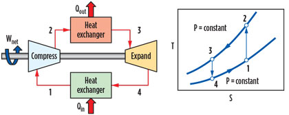
Key aspects of BR cycles. A reverse Brayton cycle, or expander cycle, supplies refrigeration by expanding vapor and extracting work. Fig. 1 shows a schematic of an ideal BR cycle. In the ideal cycle, warm, low-pressure gas (1) is compressed isentropically. The resulting stream (2) is cooled at constant pressure while rejecting heat to ambient. The cooled stream (3) is then expanded isentropically, and work is extracted to produce the cold refrigerant stream (4), which is then warmed while providing refrigeration.
 |
|
Fig. 1. Flow diagram of ideal BR cycle. |
A key aspect to consider when comparing a BR cycle to a fluid boiling or MR cycle is that the refrigeration is provided by sensibly warming the gaseous refrigeration stream (Fig. 1, steps 4 to 1). On the other hand, an MR cycle provides the bulk of the refrigeration by boiling the refrigerant mixture (latent heat). More refrigeration is provided per mass of refrigerant by latent heat, rather than by sensible heat. Therefore, a BR cycle typically requires a much larger refrigerant flowrate, resulting in larger equipment and pipe sizes for the same capacity. This scenario limits the application of a BR cycle to small- and medium-scale LNG plants. This effect can be mitigated somewhat by the use of high operating pressures, subject to mechanical design constraints.
Another key aspect of the BR cycle is that, as the refrigeration temperature approaches ambient (Fig. 1, steps 4 to 1), the expander work will approach the compressor work. The net work, Wnet, is equal to the difference between the compressor and expander work. For near-ambient refrigeration loads, Wnet is very sensitive to machinery inefficiencies. To provide refrigeration at warm temperatures, BR cycles are inherently less efficient than fluid boiling and MR cycles.
Comparison of BR cycles. For LNG production, the main BR cycle working fluids of interest are methane and N2. Both are readily available: N2 is needed for equipment inerting and purging, while methane is available from the feed gas.
Ideal process. In an ideal process, the equipment efficiency is 100%, refrigeration supply and heat rejection occur reversibly (no pressure drop or lost work), gas expansion is reversible and isentropic, and compression is also reversible and isentropic (or reversible isothermal). Since each step is reversible and ideal, the overall process will be reversible, and the process efficiency will be the same regardless of the working fluid. As working fluids, methane and N2 provide similar efficiencies in an ideal BR cycle.
Non-ideal process. In the real world, equipment is not perfect. Heat transfer and fluid transport involve pressure drop, real expanders are not isentropic, and real compressors are not reversible and isothermal. If these effects are taken into account, then methane and N2 working fluids will have different efficiencies.
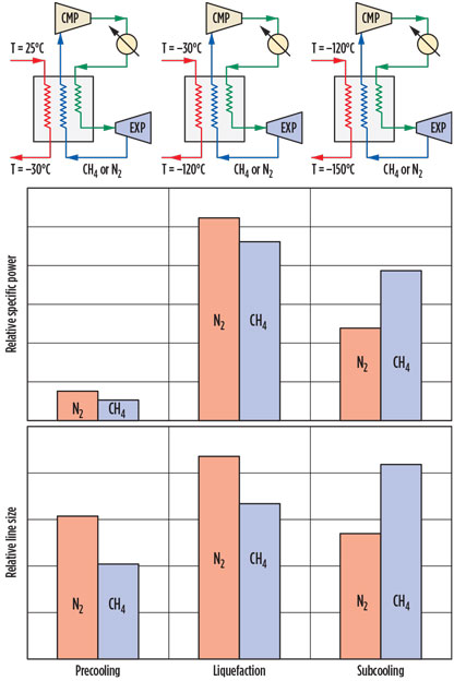
Several simple process simulations are performed to compare N2 and methane as BR cycle working fluids. Key assumptions are a compression polytropic efficiency of 80%, an expander isentropic efficiency of 80%, and a pressure drop of 0.5 bar throughout all process heat exchangers. Three discrete temperature ranges are simulated, with each step cooling natural gas feed:
- Precooling (vapor natural gas cools from 25°C to –30°C)
- Liquefaction (natural gas cools from –30°C to –120°C, and changes from vapor to liquid phase)
- Subcooling (liquid natural gas cools from –120°C to –150°C) LNG.
The specific power requirement (i.e., the required energy per unit of LNG mass produced, kWh/t) is calculated for each process, and the results for both methane and N2 are shown in Fig. 2.
 |
|
Fig. 2. Comparison of methane and N2 as working fluids. |
LNG precooling and liquefaction. Comparing the specific power requirement for a BR cycle using N2 and methane (Fig. 2) shows that methane is more efficient (i.e., has lower specific power) in the precooling and liquefaction temperature ranges. This is because methane has a lower heat capacity ratio, γ, as shown in Eq. 1:
![]() (1)
(1)
For a polytropic compression process, refer to Eq. 2:
P1 – γTγ = constant(2)
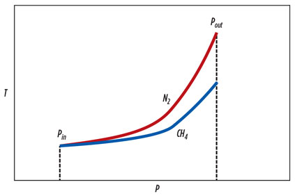
Eq. 2 shows that, for a given compression ratio, N2 will have a higher outlet temperature than methane, due to the higher γ. This means that more work is expended as the compression proceeds, due to the higher temperature. Additionally, more lost work will be incurred during the heat rejection step. This effect is illustrated in Fig. 3. The increased heating of N2 compression can be mitigated somewhat by additional compressor intercoolers. However, the intercooling process causes additional pressure drop losses, making the compression of methane more efficient than N2 compression.
 |
|
Fig. 3. Polytropic compression process. |
Also shown in Fig. 2, the pipe sizes for methane are smaller than for N2, for both the precooling and liquefaction services. This situation can be explained by the higher CP (or constant pressure heat capacity) for methane than for N2. Due to the higher CP, less mass flow is required to provide the same cooling duty, resulting in smaller line sizes.
LNG subcooling. The results are different for the LNG subcooling stage, which provides the coldest refrigeration. For the subcooling portion of the process, the N2 BR cycle is more efficient than the methane BR cycle, and it also requires smaller line sizes. This is due to methane’s comparatively low vapor pressure. The vapor pressure of the fluid at the coldest temperature in the process (–153°C) sets the maximum pressure at the expander outlet. The vapor pressures for methane and N2 at –153°C are 1.9 bara and 25 bara, respectively.
Since the pressure drop loss is proportional to the absolute pressure, warming methane at a low pressure results in high pressure drop losses while decreasing the overall efficiency of the process when methane is used as the working fluid. In addition, the lower pressure results in higher volumetric flows and, therefore, larger line sizes, despite the higher
heat capacity.
Entire liquefaction process. Although methane has better performance for the precooling and liquefaction stages, the optimal BR cycle working fluid is N2 when a single fluid is used for the entire LNG liquefaction process (i.e., precooling, liquefaction and subcooling). Overall, the advantage of methane for precooling and liquefaction refrigeration is outweighed by its disadvantages for providing subcooling refrigeration.
BR cycle liquefaction processes. The key to developing any natural gas liquefaction process is to select the appropriate refrigeration cycles to provide refrigeration duty for each of the precooling, liquefaction and subcooling sections. Various liquefaction processes utilizing BR cycles are discussed.
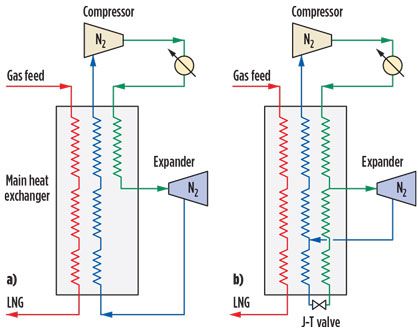
N2 recycle expander process. The well-known technology is based on a BR cycle that uses gaseous N2 as refrigerant. The simplest N2 expander cycle has only one expander, as shown in Fig. 4a. In this process, the pure N2 refrigerant is compressed and cooled subsequently in the aftercooler and in the main heat exchanger, and then expands to a low pressure and a low temperature. The N2 refrigerant maintains a gaseous state throughout the process, providing the required refrigeration for the entire temperature range of the process, including the precooling, liquefaction and subcooling sections.
 |
|
Fig. 4. Single-expander N2 BR cycles. |
To make the single-expander N2 process more efficient, a portion of the high-pressure N2 can be taken before the expander, further cooled and liquefied, and then expanded through a Joule-Thomson (J-T) valve. In this process (Fig. 4b), some of the refrigeration for the subcooling step comes from vaporizing liquid N2 rather than from warming up low-temperature N2 vapor.
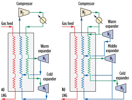
Higher process efficiencies can also be achieved by adding more N2 expanders, which allows more dedicated refrigeration to each of the temperature ranges. Fig. 5a shows one such process, where a warm expander provides precooling and liquefaction refrigeration, while a second (cold) expander provides subcooling refrigeration.
 |
|
Fig. 5. Two- and three-expander N2 BR cycles. |
The low-pressure N2 from the cold expander, after providing refrigeration to the subcooling section, rejoins the low-pressure N2 from the warm expander and continues to provide refrigeration to the liquefaction and precooling sections, as shown in Fig. 5a. This configuration can be further improved by allowing a third (middle) expander to provide dedicated refrigeration to the liquefaction section, as shown in Fig. 5b.
In these two configurations, all of the N2 expanders have essentially the same discharge pressure. After the N2 has provided refrigeration to the natural gas, it is warm-compressed from a single-suction pressure by the N2 compressor and then circulated through the process.
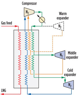
A lower expander discharge pressure is preferred for LNG subcooling, while a higher pressure is preferred for the precooling and liquefaction stages. To further improve the process, a dual-pressure N2 expander BR cycle can be used (Fig. 6). This allows the warm and middle expanders to have higher discharge pressure than the cold expander, further improving the process efficiency.
 |
|
Fig. 6. Two-pressure-level N2 BR cycle. |
The low-pressure N2 refrigerant from the cold expander and the medium-pressure N2 refrigerant flow, in parallel, through the main heat exchanger and are compressed at different suction inlet pressures by the N2 compressor. The dashed lines show an optional third (warm) expander for better efficiency.
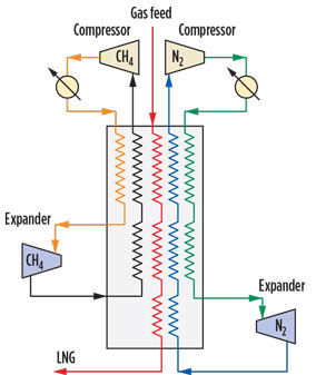
‘Hybrid’ methane N2 expander process. Methane can be a more efficient refrigerant for the precooling and liquefaction stages in a BR LNG liquefaction cycle. Therefore, the warm and middle expanders in Fig. 6 can be replaced by a separate, methane-based BR cycle, resulting in a “hybrid” BR cycle, as shown in Fig. 7.
 |
|
Fig. 7. “Hybrid” methane-N2 expander cycle. |
The cold N2 expander is retained to provide efficient subcooling. Similar to the multi-expander N2-based BR cycle, the efficiency of this process can be improved by using two or more methane expanders. A disadvantage of this process is that the two separate refrigeration loops add capital cost and operating complexity.
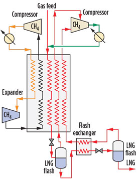
Integrated methane expander and flash cycle. To maintain high process efficiency and completely eliminate the separate subcooling refrigerant loop (e.g., N2), the cold N2 expander can be replaced by a series of LNG flashes, each at subsequently lower pressures. This setup leads to the integrated methane expander and flash cycle (Fig. 8).
 |
|
Fig. 8. Integrated methane expander and |
The process includes two flash steps. The process efficiency of the cycle could be incrementally improved by adding more flash steps, but this would increase the capital cost. This innovative process is suitable for FLNG applications, with several primary advantages:
- Similar to the N2 expander processes, it is insensitive to vessel motion
- Compared to MR cycles, the quantity of flammable refrigerant is minimized because the methane is in the gas phase
- The process has high efficiency and requires relatively small equipment and piping sizes
- Methane refrigerant is readily available from the feed gas, minimizing the footprint of the refrigerant storage and makeup systems, which is important for FLNG applications
- The refrigerant side and the process side have the same molecules. This eliminates potential cross-contamination of the two streams and its impact on process efficiency and plant operation.
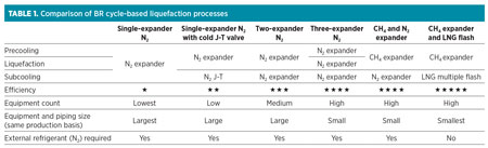
A comparison of the various BR-cycle-based liquefaction processes is summarized in Table 1.
 |
Recommendation. BR cycles are typically suitable for small- to mid-scale LNG plants and offer some advantages for FLNG applications due to lower flammable hydrocarbon inventory and insensitivity to motion. Both N2 and methane can be used as a working fluid in BR cycles. The optimal working fluid is N2 when using a BR cycle with a single working fluid for the entire LNG liquefaction process (precooling, liquefaction and subcooling).
If the stages in the process are considered separately, methane performs better at the precooling and liquefaction stages, due to favorable thermodynamic properties (Cp/Cv). On the other hand, N2 as a working fluid gives a better efficiency at the subcooling stage, where the methane cycle leads to very low suction pressures.
Multiple expansion cycles give opportunity to further improve the efficiency and other performance factors. The integrated methane expander and flash cycle is a newly developed process that offers high efficiency, simplicity and reduced footprint, making it attractive for small- to mid-scale LNG plants, and particularly for FLNG applications. GP
LITERATURE CITED
1Balascak, L., S. Trautmann and J. Wehrman, “Technical challenges of biogas as an LNG feedstock,” Tekna, Small Scale LNG, Stavanger, Norway, 2014.
2Bronfenbrenner, J. C., “Selecting a suitable process,” LNG Industry, Summer 2009.
3Balascak, L., D. Healey, W. Miller and S. Trautmann, “Air Products’ technologies for small scale LNG,” Small Scale LNG, Oslo, Norway, 2011.
4Bukowski, J., Y. Liu, M. R. Pillarella, S. J. Boccella and W. A. Kennington, “Natural gas liquefaction technology for FLNG facilities,” 16th International Conference and Exhibition on LNG, Houston, Texas, 2010.
5Roberts, M. J., et al., “Liquefaction method and system,” US Patent 8464551, 2013.
6Roberts, M. J., et al., “Hybrid cycle for the production of liquefied natural gas,” US Patent 6308531 B1, 2001.
7Roberts, M. J., “Reducing LNG capital cost in today’s competitive environment,” 14th International Conference and Exhibition on LNG, Doha, Qatar, 2004.
8Pillarella, M., et al., “The C3MR liquefaction cycle: Versatility for a fast-growing, ever-changing LNG industry,” 15th International Conference and Exhibition on LNG, Barcelona, Spain, 2007.
9Haouari, A., “Successful startup of QG mega LNG trains,” 20th World Petroleum Conference, Doha, Qatar, 2011.
 |
Mark J. Roberts joined Air Products in 1996 and has 26 years of experience in developing cryogenic cycles for gas separation and liquefaction. He has more than 30 patents issued in his name, including the patent for the AP-X process. His responsibilities as an engineering associate, LNG, include leading the development of new approaches to LNG liquefaction, and support of sales estimates for Air Products’ LNG business.
 |
Fei Chen joined Air Products in 2009 and has held various positions within the company. He is currently a senior principal engineer with responsibilities including process engineering, plant startup and system engineering, and new cycle and technology development. Dr. Chen has
worked on several baseload LNG projects and focuses on process engineering for mid-size LNG projects. He received his BS and MS degrees from Tsinghua University in Beijing, China, and his PhD from the Massachusetts Institute of Technology, all in chemical engineering.
 |
Öznur Saygı-Arslan joined Air Products in 2010 as a participant in the career development program. For her first assignment, she worked on the development of a method to design innovative heat exchangers to support FLNG applications. She currently works in the research and engineering group, which designs LNG cycles and LNG heat exchangers. Dr. Saygı-Arslan received her BS and MS degrees in chemical engineering from Bogazici University in Turkey, and was awarded her PhD in chemical engineering from Lehigh University in Pennsylvania.


Comments