
Maximize cost and safety benefits of scavenging H2S at the wellhead
B. Bowers and E. Cash, Valerus, Houston, Texas
It has been estimated by multiple parties that roughly 19 Tcf of natural gas exists in the US in reservoirs that are contaminated with hydrogen sulfide (H2S). H2S is also present in proven major liquid plays, such as the Permian basin and the Eagle Ford shale. With advancements in seismic and drilling technologies, as well as the expanded ability to handle this deadly and corrosive gas, these once-circumvented reserves are now prime targets for exploration due to their potential for high returns.
Low-concentration H2S has been commonly treated with solid absorbent beds for the last 100 years, but with the growth in the US unconventional oil and gas industry, liquid chemical scavenger systems have been designed and field tested to increase H2S extraction efficiencies.
H2S treatment options and cost. Balancing the cost of the different types of H2S treatment against raising the specifications for production equipment is a dilemma facing exploration and production (E&P) companies today. High-pressure (HP) scavenging applications are easier for the developed contactor technologies to handle in reasonably sized equipment.
Low-pressure (LP) applications, on the other hand, typically cause issues due to high velocities and the resulting lack of contact time, unless the contactor is very large. Processing trains for the LP, untreated applications use equipment with high-alloy steel that is relatively expensive.
E&P companies willingly design their equipment to comply with NACE International requirements, not only to increase the lifespan of the equipment, but also to protect their operating personnel from any mechanical failure that might result in the release of H2S and, possibly, death. The economics of the many different H2S-extraction systems has been a hot topic with the rise and fall of the oil and gas markets, but now the focus has shifted to scavenging at the wellhead, for a number of reasons.
Removing H2S as early as possible in the production stream rids this poisonous gas from the downstream equation of corrosion and safety. Both “facility lifespan” and “level of threat to human life” are becoming the most significant design details in today’s facilities for E&P companies drilling in H2S-prone reserves.
Based on the successful use of relatively complex, but robust and industry-recognized, technologies for HP wellhead scavenging, the E&P base is increasingly becoming more motivated to extract H2S in LP applications. Whether to compress and gather sour gas or to simply cut H2S emissions from offgas at the flare, the LP scavenging system has the attention of production equipment providers and facility designers alike.
H2S and its nature, as well as a few of the common methods for treatment, are described here. The system reviewed in both the HP and LP cases is a patented scavenger system. The operational issues with this system in an LP case and the design upgrades to deal with high velocity are discussed. Additionally, the expense of alloy steel content in the downstream production equipment train is examined.
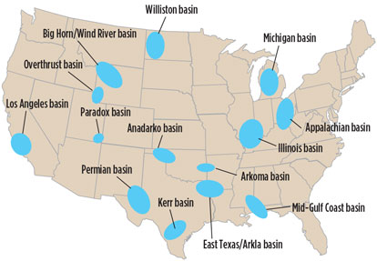
H2S frequency and existing issues. US geographical regions that have H2S are shown in Fig. 1. These basins have been proven territories for H2S in low concentrations as well as in high concentrations.
 |
|
Fig. 1. US basins that have H2S in the gas stream. |
Areas that are heavy in liquid production vs. gas production tend to have more intensive drilling programs. Both oil and gas hydrocarbon products, no matter the population density, fall under the same H2S containment regulations governed by local and federal environmental protection agencies.
An issue in liquid plays, for example, includes extracting H2S from the offgases emitted from the large volumes of recovered liquid hydrocarbons. Typically, in the first stage of separation, the HP gas is separated from the liquids and routed to a gathering line for central processing, where more traditional H2S treating and gas dehydration occur.
Successive stages of separation result in lower-pressure offgases rich with H2S that cannot travel down the HP gathering line; therefore, they must either be recompressed or burned at the flare. The offgases from the treater and tanks are even lower in pressure than gases from the LP and intermediate separators.
In many cases, recompressing untreated H2S gas at such low pressures with a local vapor recovery unit is damaging to the unit. H2S can contaminate the lube oils in the compressor, and, depending on the H2S content, the small compressor may need to be upgraded with alloy steel components to handle the corrosive nature of the gas.
On the other hand, if the producer opts to burn the offgases at the flare, another set of regulations are encountered. Oil-field flares with a full-time automatic pilot can normally claim a destruction rate of at least 98%. The remaining 2% must be logged and calculated to ensure that it does not reach the permitted threshold for annual emissions. The flare must be tall enough to allow the H2S gas to disperse into the atmosphere in case of a loss of flame (typically a 40-ft minimum height), as well as for the safety of the operators and communities in the surrounding environment.
Each alternative requires an upgraded, more expensive component and results in higher operational expense to maintain integrity. While vapor recovery recoups some expense, the flare is a complete loss of the LP product and, in some cases, overloads the emissions permit maximum.
Issues in major gas plays are often similar to the vapor recovery aspect of the liquid plays, in that the gas from LP wells, in most cases, must be compressed to travel to a central facility for further processing. Much larger compressors must be equipped with corrosion-resistant alloys capable of handling the low pH that is exacerbated by the increase in H2S partial pressure once the gas is compressed. The typical protective equipment for the compressor, such as filter separators and after-scrubbers, must also be improved with alloy steels to handle the H2S content.
Maintenance management programs for compression packages and consumable gas processing equipment, such as the elements in the filter separator, become difficult and dangerous for the technician responsible for the upkeep of such equipment. Maintenance teams must work in pairs, or even in groups, to keep one person available for rescue in case of H2S exposure of a team member. The procedures and efforts required for safe operation increase operational expenses.
Why is natural gas treated to extract H2S? Prevention of death or injury to operating personnel or populations in close proximity to an H2S-contaminated well is the primary reason for gas treatment. Additional H2S-monitoring systems increase the annual safety expense of a facility, as such sensors must be frequently tested.
Extracting H2S from the hydrocarbon stream early in the process train can greatly extend the life span of midstream and downstream equipment. NACE International requirements for processing equipment can increase equipment costs by 20% to 40% when designing to MRO175 requirements for sulfide stress cracking. Some steels can fail within 30 minutes of exposure to 50 ppm of H2S in pressurized environments.
Stress corrosion cracking (SCC) studies based on calculating partial pressure are commonly conducted to reduce the failure of metallic components within any given system that comes in contact with H2S or other corrosive streams. Elevated partial pressure of H2S results in the lowering of pH, and, when operating at high temperatures, the resulting stream can be highly corrosive, a condition common in the case of compression.
In all cases, raising the nickel content in pressurized equipment greatly increases the cost of the equipment. Protecting investments and increasing process train longevity are goals for all E&P companies.
H2S is also a pollutant to the environment. For this reason, total emissions must be logged and reported on an annual basis to environmental regulating bodies. The recordkeeping alone is an added operational expense, and there are strict limits on the amount of H2S allowed to be released into the atmosphere. If these limits are surpassed, fines can be imposed and closer oversight in the form of environmental audits can result.
High H2S levels also negatively affect the marketability of natural gas. For example, the pipeline-specified limit for H2S content of natural gas is generally set at 4 ppm. If this limit is not met, the gas buyer can shut in or refuse to take the gas from the seller.
Traditional methods of H2S extraction. The traditional amines, monoethanol amine (MEA), diethanol amine (DEA), and methyldiethanol amine (MDEA), are regenerable amines that are mixed with water in a specific ratio for use in an H2S-removal system. The amine is placed in contact with the gas stream in a contactor, where it absorbs/reacts with the H2S in the gas stream. The “rich” amine is then pumped into a reboiler, where it is heated to regenerate the amine to drive off the absorbed H2S. The regenerated “lean” amine is then pumped back into the contactor to repeat the cycle.
This is a closed-loop system and must have HP gas for optimal performance. Typical use would be at a gas gathering station after compression, or in an HP-producing field. At present, about 15% of all produced gas is sour, much with low concentrations of H2S and also small-volume flows.1 The amine regenerating system is a complex unit to operate and requires daily attention, resulting in increased operating costs.
Solid media canisters are large holding vessels (Fig. 2) that typically contain a sulfur-treating media or an iron sponge through which the gas stream flows. The gas makes contact with the absorbent media, and the H2S bonds to the media as it passes through the canister. The saturation rate for the media must be calculated, and the canister size and media volume must be matched to the particular gas stream flowrate and H2S concentration.
 |
|
Fig. 2. Solid media canisters are large holding vessels that typically contain a |
H2S solid media canisters require the media to be manually removed from the canister upon saturation and placed in drums. Each drum must be identified on a manifest, and the manifest, by law, must be kept in the company’s records at all times. If a drum ruptures in storage, then the responsible party must pay for cleanup. Removal and replacement of the solid media is a dirty and smelly experience not favored by most operators.
Also, if adequate protection is not installed downstream of the canister vessel, then the solid media can contaminate downstream equipment. Media changes will range in frequency due to the size of the vessel, the amount of media, the gas flowrate and the H2S concentration. The expense of each change and disposal, as well as the associated resources required, have pushed some companies to adopt a more convenient design.
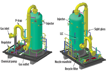
H2S liquid scavenging systems. In most cases, these systems (Fig. 3) use some form of triazine with different preferred additives. There are a number of contactor systems available on the market, and some operators have even used gas dehydration contactors for liquid scavenging.
 |
|
Fig. 3. Diagram of an H2S liquid scavenging system. |
The concept is the same for all scavenging systems where natural gas and preferred chemicals are placed in countercurrent flow for maximum contact. Most chemicals are not regenerative in these systems and are sent to a waste tank after being spent.
These waste chemical byproducts are easy to manage since they can be dispersed into produced water storage tanks for storage and disposal along with the produced water. The produced water can be disposed of in any saltwater disposal well with no manifest required. This system features a low complexity of operation after startup; two pumps are used to inject fresh and recycled chemical, and the recycle loop filter is changed every three to four days, depending on the application.
Split-streaming the sour gas stream to fully treat a side stream and then blending back into the untreated main stream is one strategy that has been proven to be effective in meeting an H2S spec without excessive equipment cost. This practice is typically used to protect downstream equipment and/or meet a sales line H2S specification. It can greatly reduce the chemical consumption.
Advantages of scavenging at the wellhead. Benefits of H2S removal at the wellhead include, but are not limited to:
- Improved operations and maintenance personnel safety
- Improved preservation of equipment mechanical integrity
- Reduced production and compression equipment cost
- Reduced annual emissions tonnage
- Reduced environmental and safety risks
- Reduced downstream H2S-monitoring expense
- Reduced safety personnel count
- Increased longevity of equipment
- Reduced downstream H2S contamination
- Steady flow to sales and no downstream shut-in due to H2S content.
Targeting economic chemical efficiencies. A liquid chemical H2S scavenging system must be used in a resourceful manner to maximize the value of the process. Most triazine-based systems cannot economically treat over 2,000 ppm, or 0.2%, H2S content.
Carefully defining the process conditions and scope, as well as understanding the H2S target, is vital to developing the best and most productive approach to H2S-removal systems. The criteria for selecting an effective chemical includes checking cost and availability, as well as verifying chemical vendor claims relative to disposal liabilities.
Typical claims for triazine scavenger byproducts include:
- Water-soluble proprietary formulation
- Non-aldehyde/non-oxidizing; product has sufficient ethanolamine for complete aldehyde reaction
- For natural gas/liquid hydrocarbon/brine
- Forms thermally stable water-soluble reaction byproduct
- Reaction byproducts are classified as nonhazardous
- Contains scale-inhibitor package to prevent formation of mineral scale.
Chemical consumption is key to the economics of the scavenging process. Chemical efficiency is dependent on the mass percent of triazine or on generic blends of scavenger chemical. Eq. 1 is commonly used to balance chemical consumption to set rates:
H2S ppm × MMscf/d × 0.06 = gpd of chemical consumption(1)
Example: 100 ppm × 1 MMscf/d × 0.06 = 6 gpd of chemical consumption.
Due to the designed bubble-up with atomized gas contact, this combined process enables controlled, constant, maximum loading of triazine with recirculation (recycle) from the bottom to the top of the tower, as well as internal dispersion of gas and a highly efficient injection design. This assortment of internals reduces chemical consumption by reaching 80% of the triazine reaction or triazine’s full potential in this system.
One patented scavenger system routes the sour gas stream through a two-stage process. First, the inlet gas is sparged through a pool of liquid triazine, and then the pretreated gas is exposed to a mist of fresh triazine in the upper section of the contactor.
The first reaction with triazine takes place in the liquid chemical pool. The gas rises upward in a countercurrent flow with the triazine chemical. The gas is finely dispersed through multiple perforated baffles that increase the gas-chemical agitation and gas-chemical contact surface area. The gas then rises out of the liquid pool into the misting section, where a combination of fresh and recycled chemical is sprayed into the top of the vessel through atomizing nozzles. This allows the pretreated gas to come into intimate contact with fresher chemical, facilitating a second reaction that takes somewhat longer than the relatively instantaneous first reaction in the liquid-filled lower section of the contactor.
As the gas rises through the fresh chemical spray, any residual H2S is polished from the gas to an H2S content of less than 1 ppm. The gas travels up through a mist extractor and exits the top of the contactor. The spent chemical is collected in the bottom of the vessel for disposal into the produced water tanks.
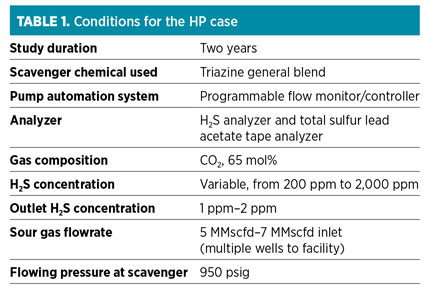
Case histories. Following is a comparison of two separate case studies that examine the difference between HP and LP scavenging at the wellhead. The HP case exhibits the success and ease of scavenging due to the HP, as well as showing its ability to handle high-CO2 content. The LP case shows the issues that arise due to the high velocity. LP targets are below 150 but above 50, and gas-to-chemical contact is reduced. Table 1 lists the conditions, results and proposed adjustments.
In the HP case, an operational issue was encountered. Compression upstream of the scavenger caused the condensation of free hydrocarbons and free water in the discharge of the compressor, resulting in these liquids entering the scavenger system contactor, diluting and displacing chemical and causing sulfur compound precipitation.
Corrective actions included:
- A filter separator installed at the compressor discharge to remove free liquids; however, the temperature drop entering the scavenger system contactor caused further condensation of hydrocarbons in the contactor
- Routine monitoring of the sight glass to detect hydrocarbon liquid accumulation, allowing periodic draining to prevent chemical contamination
- Increasing the compressor discharge temperature (i.e., the scavenger system inlet temperature) to 120°F to help keep hydrocarbons in the gaseous state through the scavenger system.
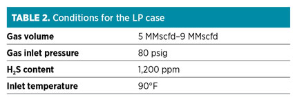
Table 2 shows conditions for the LP case. Operational issues included:
- Could not reduce outlet H2S content below 4 ppm
- Sulfur compounds precipitated in the mesh pad
- Gradual, excessive loss of chemical through the gas outlet of the contactor.
Corrective actions included:
- Placed a backpressure valve on the contactor vessel to reduce variations in instantaneous gas flowrate and to maintain a consistent operating pressure
- Placed an after-scrubber downstream to recover any chemical carryover
- Increased the chemical injection rate to prevent precipitants from forming on the mesh pad; additional fresh chemical diluted the total chemical enough to maintain fluidity; if the triazine is allowed to reach the third reaction, then elemental sulfer will precipitate and block flow.
Problems presented by scavenging at LP. For a given gas flowrate and contactor size, the lower the pressure, the higher the velocity through the contactor. High velocities reduce the contact time with the triazine chemical, resulting in inadequate time for the transfer of sulfur from gas to scavenger chemical. This results in a high H2S content in the discharge of the contactor, and chemical that is not yet 80% spent may be dumped to the waste tanks early.
High gas velocity through the contactor also tends to sweep chemical through the mist extractor and out of the contactor.
Finally, if the mist extractor stays in contact with high H2S gas, then the scavenger chemical trapped on the mist extractor can become saturated with sulfer, resulting in solids precipitaton. This can plug the gas outlet of the vessel with the mist extractor, acting as a structural skeleton for the sulfur debris to build upon.
Aside from solids precipitation, these problems are similar to those encountered in triethylene glycol (TEG) gas dehydration systems when operated at low pressure. In this analogy, LP operation can result in glycol losses and inadequate transfer of water vapor from gas to glycol.
Design modifications to improve LP scavenging. For a larger vessel, increasing the diameter and height of the contactor vessel provides additional contact time for the transfer of sulfur compounds from gas to scavenger chemical. Increased diameter decreases superficial gas velocity, reducing chemical carryover to the gas outlet. Ultimate contactor sizing will be constrained by practical transportation limits for the equipment.
A larger vessel will require a larger initial fill of chemical, representing a higher upfront expense. However, this does not equate to a higher operating expense, as chemical consumption in a well-operated system will be directly proportional to the amount of sulfur removed from the gas.
For a thinner-walled vessel, LP operation allows a thinner wall in the contactor vessel, with significant reduction in equipment cost. Additional dispersion baffles can be added to increase agitation of the gas and chemical to partially offset any reduction in contact time, while additional injection nozzles to more completely fill the upper section of the contactor aid in contact efficiency.
Full-time monitoring and automation greatly optimize the operation of any liquid scavenger system, but are especially beneficial in LP systems. These automation systems use a feedback loop sensing H2S in the gas outlet of the contactor to control the fresh chemical injection rate into the contactor. By optimizing the chemical injection rate, only the minimum amount of chemical required to achieve the outlet H2S specification is consumed. The automation system can also be tuned to prevent undertreating, such that the scavenger chemical never becomes saturated with sulfur compounds, mitigating concern for solids precipitation in the contactor or downstream piping.
Additionally, a combination of fresh and recycled chemical lines can reduce the likelihood of formation of precipitants in the contactor vessel. This method has been proven to maintain an undersaturated injected chemical mixture, and it also reduces solids precipitation in the recycled chemical filter.
Recommendations. Modifications to the patented scavenging system for LP applications promise to bring greater economic benefit over the operational life of the unit. The first applications for the patented scavengers were on HP designs and have proven highly effective.2 With the growth in demand for LP scavenging systems in US shale plays, the development of an LP scavenger offers exciting options for managing sour gas production at the wellhead.
The overall benefits of H2S removal are still weighed the same as in HP applications, and they outweigh the cost of closely monitored chemical consumption. Chemical technologies, such as regenerative scavengers, coupled with LP design to further reduce the cost and boost the economic benefit, is an area of future research. Field testing on the patented technology will continue to support necessary design engineering changes, and a new patented product is expected to be developed and proven between late 2015 and mid-2016. GP
Literature cited
1Foral, A. J. and B. H. AI-Ubaidi, “Evaluation of H2S scavenger technologies,” GRI Report No. GRI-94/0197, prepared for Gas Research Institute Contract No. 5088-221-1753, 1993.
2Amosa, M. K., I. A. Mohammed and S. A. Yaro, “Sulphide scavengers in oil and gas industry—A review,” Nafta Scientific Journal, Croatia, 2010.
 |
Bill Bowers is vice president of Valerus’ production equipment product line in Houston, Texas. He has over 35 years of experience working for both producers and service companies in a variety of engineering and management roles, supporting the applications, design and manufacture of oil and gas production and processing facilities. Prior to beginning his oilfield career with Schlumberger, Mr. Bowers earned a bachelor’s degree in electrical engineering at the Georgia Institute of Technology in Atlanta, Georgia.
 |
Ed Cash is the director of ET processing and one of Valerus’ founding employees. Prior to joining Valerus in 2004, he worked at Hanover Compression specializing in the design and sale of process equipment. Mr. Cash has over 40 years of experience in the oil field, including management positions in maintenance and operations for compression fabrication plants. He holds several US and Canadian patents for gas sweetening and processing systems.


Comments