
Pumps and Valves
G. Khiani, Fluor Canada Ltd., Calgary, Alberta, Canada
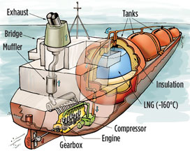
Pumps and valves for LNG service have many exclusive design characteristics and specifications that must be accounted for and followed during the development of an LNG terminal, storage tank or vessel (Fig. 1). Pumps are integrally mounted on the same shaft as the motor, which is submerged without coupling or mechanical seals in the LNG liquid.
 |
|
Fig. 1. Diagram of a vessel used in the transport |
For retractable, in-tank applications, the pumps can be installed inside the LNG storage tanks in vertical pump columns, with foot valves located at the bottom. This setup removes the possibility of tank leakage due to piping or other external problems. The pump retraction system permits the unit to be safely removed from an operational tank without venting gas vapor to the atmosphere.
By enclosing the entire unit within a suction vessel built to an appropriate pressure vessel code, such as American Society of Mechanical Engineers (ASME) 8, the system becomes safe and simple. The pump is factory aligned; there are no couplings and no auxiliary pipe work for seal purge, bearing cooling or lubrication. These characteristics make for a lightweight, uncomplicated installation.
The ability to install the pumps inside a storage vessel allows the vessel to be placed underground or to be covered by mounding. This scenario avoids the possibility of catastrophic failure, and it eliminates tank penetrations below the liquid level. It also removes the need for water deluge systems and protects the tanks from being engulfed by fire, radiation, vandalism and/or sabotage.
Key factors in the consideration of LNG application pumps are:
- Lubrication and cooling systems
- Thrust equalizing mechanism
- Bearing configuration
- Junction box (JB) assembly and electrical penetrations
- Cryodynamic inducer design
- Vibration monitoring systems.
Cryogenic pump specifications. The induction motors in cryogenic applications present certain design, manufacturing and testing challenges and advantages when compared to traditional motors. Since the fluid passes through the rotating machine components, specific design and testing parameters have been developed to incorporate the requirements of such low-temperature fluids.
Heat generation in the motor is not a concern when cryogenic fluids are moved. Tests have shown that the stator coils of a submerged cryogenic machine experience a 12°C maximum temperature increase during full-load operation.
Each motor design is project-specific and based on application requirements. Each design is also verified by a performance test. Motor manufacturing involves proprietary insulation systems, best-in-class techniques and the highest-quality materials to ensure that each unit meets design conditions.
Specifications in the consideration of cryogenic application pumps include:
- Thrust equalizing
- Bearing configuration
- JB assembly
- Electrical penetrations
- Cryodynamic design requirements
- Vibration monitoring.
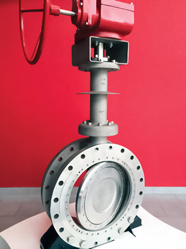
Design features of LNG valves. Valves used in LNG service (Fig. 2) are designed with an extended bonnet to avoid packing freezing at operating temperatures, and this allows operations to cycle valves when required. Valves manufactured for cryogenic applications should comply with the type tested to BS6364 or an equivalent standard; non-metallic materials should be restricted to polytetrafluoroethylene (PTFE) and graphite.
 |
|
Fig. 2. A valve used in LNG service. Photo courtesy |
Fire-safe design to prevent internal leakage is achieved by using resilient sealing materials that do not decompose or deteriorate in a fire. In a ball valve, the edge of the metal seat retainer, preloaded by the seat spring, comes into contact with the ball to shut off the line fluid, which minimizes internal leakage through the valve bore. The seat retainer also compresses.
The flexible graphite retainer packing prevents fluid leakage from between the valve body and the seat retainer. The applicable codes comply with American Petroleum Institute (API) 607 and API 2218, Fire protecting practices in petroleum and petrochemical plants.
End flanges on valves should comply with ASME B16.5 (for valve diameters up to 24 in.) and with ASME B16.47, Series A (for valve diameters larger than 24 in.). A bidirectional flow sealing mechanism is used so that each of the upstream and downstream seats of the valve is adequately maintained in contact with the ball by means of a seat spring. Line pressure further assists with this contact method.
The design of cavity pressure relief is provided to avoid trapped volatile liquid being released into downstream. A shell pressure test should be performed, as per API 598 and ASME B16.34. Test duration should be a minimum of 5 minutes for all valve components, apart from the backseat test, and all valves must undergo a seat closure test.
The supplier must demonstrate that each valve has performed a satisfactory test below –196°C (–230°F), or has been qualified by cryogenic testing for the representative sizes and ratings proposed. All raised-face valves must have a smooth surface finish, as per ASME B16.5, with a surface finish range of 125 root mean square (RMS) to 250 RMS, as per ASME B46.1. Ring-type joint-face valves must have a smooth surface finish of 63 RMS.
Face-to-face dimensions of valves should comply with ASME B16.10, ASME BS1873 or ASME API6D. Wall thickness should comply with valve design standards such as API 600, API BS5351 and ASME B16.34. Butt-welded valves must comply with the guidelines listed in ASME B16.25.
Key factors in the consideration of LNG application valves include:
- The thermal conduction and heat transmission from the low-temperature fluid should be suppressed to a minimum, while a cooling effect is provided with the help of an extension bonnet. The packing is prevented from being exposed to the low-temperature liquid, and a secure seal is achieved.
- A surface-hardening treatment with a cobalt-chromium alloy is recommended for better performance.
- A cavity pressure-relief feature should be included.
- Seat lapping is needed.
- Stem-binding prevention is achieved with PTFE/perfluoroalkoxy construction.
- Low-emission-type packing(s) should be used to avoid compression creep stress.
- The design must prevent abnormal pressure within the cavity.
- The valve should be designed to experience little to no pressure loss.
- The valve should have a fire-safe design.
- The installation of drip-plates should be considered, as needed.
- All welded sections should be 100% radio-graphed, and a die-penetration test should be conducted.
- Full traceability of the materials used, along with their compositions, is required for pressure-retaining components—i.e., body, cover, extended bonnet, bolting, shaft, seat and disc, including the ball.
- A chemical composition analysis of each cast/melt and heat batch is required for all pressure-retaining cast/forged or bar sections.
- All components must be impact tested per ASME 8, Division 1, at –196°C. GP
 |
Gobind Khiani has spent more than 20 years in the energy and power business, with more than 10 years of experience in western Canada’s oil and gas industry, and additional experience in the UK and Dubai. He is based out of Calgary, Alberta. He graduated from the University of Poona in India and completed his master’s degree in materials and mechanical engineering from the University of Calgary in Alberta, Canada. He is a registered professional engineer working in the western provinces and prairies of Canada.


Comments