
Embracing innovation and diversity in liquefaction technology—Part 2
J. G. BAGULEY and L. A. CLARK, LNG Ltd., Houston, Texas
Part 1 of this article (Gas Processing, September/October) addressed evolution in the LNG marketplace, barriers to innovation, drivers for innovation and key elements impacting liquefaction plant efficiencies. Part 2 examines two key efficiency elements in greater detail, followed by a case study for an innovative design and delivery project opportunity.
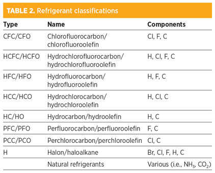
Refrigerant selection. A dizzying array of refrigerants has been named, ranging from chlorofluorocarbons (CFC)—which themselves are now avoided due to their high ozone depletion potential (ODP)—to conventional hydrocarbon refrigerants (propane, ethylene) and “natural” refrigerants, such as carbon dioxide, ammonia, nitrogen and even air.
ANSI/ASHRAE 34 (American National Standards Institute/American Society of Heating, Refrigerating and Air-Conditioning Engineers) names refrigerants (i.e., R12, R134a, R717) according to a protocol, established initially by DuPont, that describes a shorthand way of identifying refrigerants, and also assigns safety classifications based on toxicity and flammability data. A typical list of ASHRAE-named refrigerants encompasses more than 300 compounds and can be broadly classified into the categories shown in Table 2.
 |
Refrigerant selection criteria vary widely with application (i.e., automotive vs. large industrial have very different objectives). Of increasing importance are environmental issues, including ODP, global warming potential (GWP) and efficiency (which indirectly impacts GWP). LNG projects, by their nature, are effectively restricted to those refrigerants that are suitable for the significant cooling duties and low temperatures necessary to liquefy natural gas in large or very large quantities. This restriction, combined with availability considerations and the cost of the refrigerants themselves, has resulted exclusively in the selection of hydrocarbon (HC) refrigerants for cooling and liquefaction duties.
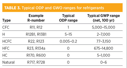
ODP value ranges. ODP ratings were established in the early 1980s due to emerging concerns over the loss of earth’s high-atmospheric ozone layer and the potential impact on human health. The ODP of the once-common CFC refrigerant R-11 (trichlorofluoromethane, CCl3F) was set at 1, and others were rated relative to this base. All of the CFC ODPs are in the range of 1 and are no longer widely used.
GWP value ranges. The concern over the potential impact on earth’s climate of chemical releases has focused increasing attention on the GWP of various compounds. In LNG plants, the refrigerants are used in closed-loop systems, limiting releases to fugitive emissions and maintenance releases. The GWP of CO2 is set at 1.
Natural refrigerants are starting to garner more attention due to their zero ODP, low (or zero) GWP and inherently high efficiencies. Natural refrigerants are chemicals that occur in nature’s biochemical processes. These products were widely used prior to the 1950s, before fluorocarbon refrigerants became commonplace, with some being used in industrial refrigeration applications (i.e., ammonia refrigerant for ice production) in the 1800s. Common natural refrigerants include carbon dioxide, ammonia, nitrogen and even water. Hydrocarbon refrigerants are often classified as naturally occurring.
Gas turbine selection. As discussed previously, gas turbine-driven LNG plants represent an inherently efficient approach to delivering refrigeration power, as intermediate (efficiency-reducing) components are eliminated when gas turbines are coupled directly to refrigeration compressors.
It is important to recognize that there is no ideal solution. One size or type is not best for all applications; a number of different sizes and types of gas turbines have been successfully utilized for LNG plant compressor drivers. Key considerations in selecting a gas turbine driver for an LNG plant application include:
- Matching gas turbine power to compressor load. Gas turbines are available only in specific, discreet sizes and operate most efficiently when running at 100% power. Efficiencies drop off below 100% load, and, depending on the turbine characteristics, radically drop off below 70% load. Consequently, the plant designers must aim to align plant size and compressor duties with available turbine sizes to obtain the greatest efficiencies. Helper motor/turbine arrangements can help ensure maximum gas turbine power utilization in some arrangements.
- Commonality. Plant designers seek to provide uniformity to the selection of gas turbines across the facility, applying the same machine in multiple services. The advantage of this approach is to minimize costly spare parts requirements and facilitate familiarity with the machines for operations and maintenance. The potential disadvantage is sub-optimizing the process design—i.e., fitting the process to the turbines rather than vice versa. Some gas turbine-powered plants have elected to increase process and operations complexity to enable commonality of drivers to be achieved.
- Type of gas turbine. Generally, aeroderivative gas turbines are more efficient than industrial frame machines, as they consume less fuel per unit of delivered power. Aeroderivative machines typically require higher fuel pressures, are more sensitive to fuel composition variations and ambient temperature variations (which can be addressed with inlet air chilling), and generate greater quantities of NOx pollutants but less CO2 per unit of delivered power than industrial frame machines. Aeroderivative gas turbines are commonly more tightly packaged than industrial frame units, with arrangements yielding easier/faster core swaps.
- Cost. The higher efficiencies and tighter packaging of the aeroderivative machines typically come with a higher initial CAPEX than industrial frame machines, although commercial competition can narrow these costs significantly.
- Maintenance requirements. Maintenance needs vary significantly between machines and must be assessed carefully. Considering long-term LNG facility operations, the two most substantial OPEX costs are personnel salaries and gas turbine maintenance.
- Shaft design. Single-shaft gas turbines must spin up the direct-coupled refrigeration compressor together with the gas turbine itself. To enable this, a combination of a large helper motor/turbine plus initial depressurization of the refrigerant loop is necessary to meet the gas turbine ramp-up profile. Multi-shaft gas turbines decouple the compressor load, enabling the gas turbine to ramp up largely independently of the compressor.
- Experience. As outlined above, novelty is avoided in LNG plant applications.
OSMR for the Magnolia LNG project. An Australia-based company is seeking to establish a concept of mid-scale, low-cost, efficient, reliable and repeatable natural gas liquefaction projects. The market entry project has been identified as a 4 × 2 MMtpy liquefaction facility (8 MMtpy total) on the US Gulf Coast in Lake Charles, Louisiana. The company is an emerging LNG proponent, as opposed to the major established national and international energy companies historically building and operating LNG facilities. Given this scenario, the company recognized that it would be challenging to compete for project opportunities without bringing specific advantages to the table.
Four key principles were established to deliver the necessary advantages: industry-leading capital cost; optimized plant energy efficiency; shortened development and construction schedules; and an overall smaller environmental impact footprint, including reduced carbon emissions relative to other LNG technologies. Without clear advantages such as these, investors and LNG buyers would simply stay with the established LNG producers.
The Optimized Single Mixed Refrigerant (OSMR®) process was created with these four principles as a goal, and with an emphasis on reliability and safety, to result in a facility that is relatively simple to design, construct, operate and maintain. This technology development was considered broadly, representing an execution strategy, as well as a process technology. At its core, OSMR represents an innovative combination of elements of existing technologies with inventive engineering process design and configuration in a mid-scale (nominally 1.5 MMtpy–3 MMtpy) train capacity to address the shifting priorities in the LNG market.
The creativity of this arrangement lies in the unique synchronization of all elements of the facility to achieve the maximum process and cost efficiencies in a reliable plant. Elementally, the configuration represents a precooled mixed-refrigerant (MR) liquefaction system, which in itself represents a major foundation element of the LNG industry.
 |
|
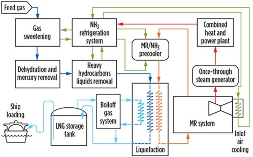
FIG. 2. Overall simplified OSMR process schematic. |
A simplified process schematic is shown in Fig. 2. Pipeline feed gas from the US gas grid is pretreated to remove sulfur, carbon dioxide and any trace mercury. It is then dehydrated and processed to remove heavy hydrocarbons that could potentially freeze in the liquefaction process. The feed gas is precooled with a single-component refrigerant, then liquefied with a mixed-component refrigerant selected to closely mimic the cooling curve of the natural gas to achieve best efficiency. The precoolant refrigerant also serves as a means to precool the MR to further enhance efficiency. The high-pressure product LNG is then flashed into storage for export.
Technology elements for success. Elements of OSMR technology that enable the project to meet the corporate objectives include precooling refrigerant selection, liquefaction and cold box selection, boiloff gas handling, refrigeration compressor driver selection and arrangement, gas turbine inlet air chilling, dual-drive arrangement, fit-for-purpose considerations and site selection.
Selection of precooling refrigerant. Larger baseload LNG facilities have historically utilized precooling refrigerant as a means to optimize the process. Propane has been the universal selection, as it represents an efficient refrigerant that is well-suited for large industrial applications and can be extracted from the feed gas of remote-location facilities. US Gulf Coast pipeline feed gas facilities (as well as coal seam gas plants in Queensland, Australia) have little to no propane in the feed gas, necessitating the import of precooling refrigerant.
 |
 |
Anhydrous ammonia (R717) was selected over traditional propane for a number of reasons. Ammonia is commonly used as a primary refrigerant across many applications and industries requiring high cooling duties, including cold storage, food and drink processing, ice production and skating rinks, as well as in ammonia production facilities themselves. NASA also selected ammonia refrigeration to provide cooling duties for the International Space Station. Supportive characteristics of ammonia refrigerant include:
- It is a readily available and relatively inexpensive refrigerant.
- Equipment costs are low. Like propane, ammonia refrigeration systems require only carbon steel and not expensive alloys.
- With lower swept volumes, ammonia refrigeration plants provide smaller equipment and piping, therebyreducing capital costs.
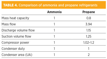
- Ammonia is a highly efficient refrigerant. A side-by-side comparison of ammonia and propane refrigeration circuits delivering the same cooling load is shown in Table 4.
- Ammonia is classified as a natural refrigerant. It is environmentally friendly and naturally occurring, with a lifecycle of less than one week. It has a GWP of zero and an ODP of zero.
- The relatively high efficiency of ammonia refrigeration also reduces indirect environmental emissions, as less energy is necessary to deliver the required cooling duty. The use of natural refrigerants is endorsed by prominent environmental stewardship groups.1
- Industry experience with ammonia refrigeration systems is extensive, and there are well-established regulatory frameworks in place. For LNG projects in the US, the Federal Energy Regulatory Commission (FERC) holds primary responsibility. Support comes from cooperating agencies, including the Environmental Protection Agency (EPA) and the Occupational Safety and Health Administration (OSHA). The more than 7,000 ammonia processes in the US are covered under the EPA Risk Management Program, including more than 2,000 ammonia refrigeration facilities. Similarly, in Australia, the Hazardous Industries and Chemicals Branch (HICB) regulates the use of ammonia in LNG plant designs.
- Ammonia is an inherently safe refrigerant choice, as evidenced by its wide use for industrial cooling duties. The toxicity of anhydrous ammonia in relatively low concentrations must be managed (by comparison, propane is a simple asphyxiant), but it provides a number of advantages:
- Ammonia is not readily flammable; in most situations, ammonia can be considered effectively non-flammable
- Ammonia is not readily explosive
- Ammonia is lighter than air, so as it warms it tends to rise and naturally dissipate
- Detection of releases in relatively low concentrations is rapid and reliable
- Mitigation of ammonia releases is reliable and effective through the use of simple water sprays due to ammonia’s high affinity to, and solubility in, water.
Liquefaction refrigerant and cold box selection. OSMR applies a patented2 MR liquefaction process using conventional cold boxes. Refrigerants are selected to best approximate the expected natural gas feedstock cooling curve, and can be adjusted during operation to optimize for changes in feed gas and seasonal variations in ambient temperature. The MR comprises nitrogen, methane, ethane and butane, all of which are readily available on the US Gulf Coast.
Boiloff gas handling. An innovative and patented1 boiloff gas handling system is applied. The boiloff gas is lightly compressed, reliquefied in the LNG train cold boxes, passed through a liquid methane separator and then returned to the LNG storage tank. This system enables recovery and reliquefaction of low-temperature boiloff gas while minimizing compression losses and compression heating that are commonly present in other design arrangements.
 |
|
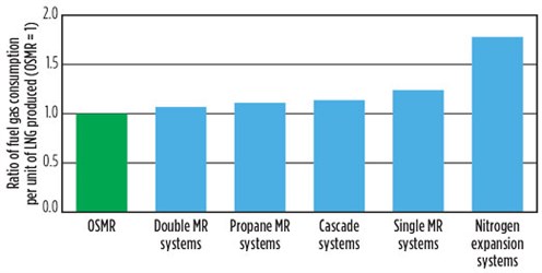
FIG. 3. Comparison of LNG plant efficiencies. |
Compressor driver selection and arrangement. One of the key elements in obtaining the high efficiencies of the OSMR arrangement is the utilization of combined-cycle refrigeration. Specifically, the MR refrigeration compressors are driven by high-efficiency gas turbines; the waste heat in the gas turbine exhaust stream is used to raise steam, which then provides the majority of the motive power for the ammonia refrigeration compressors (Fig. 3).
Consequently, not only is the ammonia system inherently efficient itself, but the ammonia compressors are also driven by energy obtained almost entirely from waste heat. (Note: A small amount of additional steam is independently raised in auxiliary boilers to enable steam balance control.)
Additionally, the MR and ammonia refrigeration strings are driven by different motive systems (gas-fired and steam-driven, respectively), with no need to force-fit the duties or add complexity to the designs to balance identical driver loads. A “best-fit” gas turbine is selected for the MR, and then the ammonia steam turbine drive is custom-designed to match, since steam turbines can be optimized to the required point. A proprietary industrial gas turbine MR driver was selected. This turbine combines the functionalities of both an industrial turbine and an aeroderivative turbine. It provides the same efficiency as similar aeroderivative units, as well as a tight package and the same high degree of maintenance accessibility, while generating low NOx emissions and providing the robustness of an industrial unit.
Gas turbine inlet air chilling. Gas turbine power output falls off with increasing ambient temperature. The selection of a high-efficiency industrial gas turbine (as opposed to an aeroderivative turbine) reduces this relationship to a degree, and the seasonal temperature variations on the US Gulf Coast are not extreme. The project location’s general climate classification is humid subtropical, with a strong maritime influence. The predominant wind direction is from the south (off the Gulf) for much of the year, which tends to subdue extreme summer heat. The average monthly high temperatures range is from 16°C (60°F) in January to 33°C (91°F) in August. Inlet air chilling using ammonia refrigerant is provided for the gas turbines, which ensures a consistent power output over the calendar year and supports replication of design in alternate locations and climates.
Dual-drive arrangement. To provide the maximum level of availability and reliability, each of the refrigeration compressors in the OSMR design is arranged in a 2 × 50% “two-in-one” arrangement. Modules 4 and 5 (see following section) each house a steam turbine-driven ammonia precooling compressor that includes the ammonia condenser and air-cooled steam turbine surface condenser. Modules 2 and 3 each house a gas turbine-driven MR compressor, MR air coolers, MR ammonia coolers and a dedicated cold box. Reliability, availability and maintainability (RAM) studies identify an availability in excess of 95%. In addition to the inherent reliability imparted (an LNG train can continue to operate at 50%+ capacity, even in the event of the loss of any single compressor), the arrangement provides excellent flexibility for turndown operations, as required to meet customer specifications.
Fit-for-purpose. The facility design team expended substantial effort to generate a simple, fit-for-purpose project consistent with the US Gulf Coast location, with access to extensive supporting regional infrastructure and organizations. Well-proven contractor and vendor standards were applied. The extent of in-plant infrastructure was optimized to take advantage of available regional services. The compact, five-module arrangement also helps meet corporate objectives; typical modular LNG plant designs necessitate a relatively large number of modules per LNG train, spreading systems and pipe racks across multiple modules and yielding a large quantity of field hookups. The OSMR approach to modularization in the mid-scale facility is to utilize only five modules for each liquefaction train, incorporating both pipe racks and process units:
- Module 1: Gas treating/utilities
- Module 2: MR liquefaction
- Module 3: MR liquefaction
- Module 4: NH3 precooling
- Module 5: NH3 precooling.
Modules 2 and 3 and Modules 4 and 5 are identical, consistent with the dual-drive arrangement outlined previously. Since the five modules are arranged by process system, coupled with integration of the main train pipe rack into the process modules themselves, module-to-module interconnections are minimized, thereby reducing the number of field hookups and the associated time and site labor necessary to accomplish project completion.
The combination of a compact site and a high level of hydrocarbon processing project activities in the site region makes modularization a necessity. Modularization also supports the corporate objective of replicating the design in subsequent projects. A substantial effort was applied to the project to minimize the physical size and weight of the process modules, thereby supporting an optimized project schedule and competitive project economics.
Site selection process. The site for the project underwent a screening study to identify the most suitable location, with the final selection made for a number of reasons:
- The land is owned by the Port of Lake Charles and zoned as industrial property, with no nearby residential or commercial retail properties.
- The site is readily accessible from existing roads, including an all-weather road running the length of the south side of the property.
- The site lies adjacent to an industrial canal (IC) and an associated turning basin on the immediate north side. The IC has been used for LNG ship transportation since the early 1980s, servicing LNG imports to the Trunkline LNG receiving terminal (slated to be put into future export service as Lake Charles LNG). Maintenance of the IC, including dredging, is the responsibility of the US Army Corps of Engineers.
- No jetty is required; a berth pocket will be dredged out of the property adjacent to the IC, and the LNG ship dock will be constructed along the new bulkhead. In addition to the absence of a jetty, no breakwater or other marine facilities outside of the mooring, breasting and loading facilities themselves are required.
- The existing, 42-in. Kinder Morgan Louisiana Pipeline runs along the south side of the property; a simple interconnect into this existing adjacent pipeline provides the natural gas feed to the Magnolia LNG facility.
- The property itself is nominally 30 ft above mean sea level, compared to a hurricane storm surge of 11 ft. The elevation was created in the 1970s as dredge spoils from the construction of the IC.
- Electrical power is available from an existing substation located less than 2 mi from the site.
- The site is within the coverage area of existing telecommunications and internet service providers.
- Hospital emergency rooms are located within 15 min of the site.
- The Lake Charles region, part of the Beaumont–Port Arthur–Lake Charles “Golden Triangle,” is home to numerous industrial and infrastructure support service organizations and contractors.
- The 115-acre size of the Magnolia LNG property, while challenging for initial construction due to the limited laydown area, is ideal for an operational mid-scale facility. Other regional LNG proponents previously discarded the location as being too small for conventional plant designs, while the compact OSMR five-module trains are well-suited to this location.
Takeaway. The LNG industry was founded on the basis of remote site liquefaction facilities shipping a critical product with limited availability to destination customers under long-term contracts. This approach fit a specific set of needs, but did not foster innovation or rapid development. With the recent transition of the liquefaction industry from the most remote corners of the planet to highly developed industrial zones, the opportunity to diversify the production of LNG has emerged. A “one-size-fits-all” approach is no longer the only choice available to further the competitiveness of the LNG industry.
End of series. Part 1 appeared in the September/October 2017 issue of Gas Processing. GP
Literature cited
- Carbajal, P. T., “Natural refrigerants: The solutions,” Greenpeace International, Amsterdam, The Netherlands, online: http://www.greenpeace.org/international/Global/international/planet-2/report/2009/5/natural-refigerants.pdf
- Australia Patents AU2008 and AU001010; and United States Patent US9003828B2 (other patents granted or pending).
 |
John G. Baguley serves as Chief Operating Officer for the Magnolia LNG and Bear Head LNG projects, and as Chief Technical Officer for LNG Ltd. His involvement in international LNG project development and delivery spans nearly 37 yr and includes project management, engineering, construction and commissioning roles. He holds a BS degree in chemical engineering from Michigan State University and is a registered Professional Engineer in Texas.
 |
Lincoln Clark is the Group Engineering and Operations Manager for LNG Ltd. He has 25 yr of experience in oil and gas projects covering the design, construction, commissioning and operation of LNG plants, gas processing facilities, oil production facilities and power stations. Mr. Clark joined the LNG Ltd. team in 2005 and has been closely involved with the development of the Gladstone LNG, Magnolia LNG and Bear Head LNG projects.


Comments