
Evaluate the cause of reduced capacity in a TEG dehydration system
M. H. Sheilan, Amine Experts Inc., Calgary, Alberta, Canada; and R. H. Weiland, Optimized Gas Treating Inc., Houston, Texas
Moving gas from offshore production platforms to onshore processing facilities via a subsea pipeline usually requires that steps are taken to prevent the formation of hydrocarbon and gas hydrates. Preventive measures include: the addition of methanol (CH3OH), monoethylene glycol (MEG) or diethylene glycol (DEG) to the gas before transmission; and the removal of water to a concentration outside the hydrate formation region by absorbing water into triethylene glycol (TEG), usually in a packed absorber situated on the production platform.
Here, a case study is presented to determine the cause and remedy for the severely reduced capacity of a TEG train in an offshore facility. As part of the remedy, it was suggested to increase the temperature of the lean TEG. However, concerns arose that a hotter lean solvent would fail to produce a dry enough gas. A simulation of this facility showed that, contrary to what might be expected from equilibrium charts, drying is hardly affected by lean solvent temperature. Rather, the temperature of the wet feed gas has the most significant effect on the dewpoint of the dry gas. The reasons behind this finding are explored in this work.
Glycol system evaluation. A fairly conventional TEG unit takes high-pressure wellhead gas to a –5°C dewpoint (approximately 50 ppmv at the operating pressure) for transfer via pipeline to an onshore LNG production facility. Additional stripping of the lean solvent was completed by sparging dry stripping gas [98.5% methane (CH4), and the balance water] directly into the regenerator’s reboiler. High liquid-level trips on the flash drum and, to some extent, the accumulator, were occurring at random, but so often that gas production was seriously compromised.
Foaming tests on the lean and rich glycol were negative—neither appeared to have any foaming tendency. However, water carryover from the inlet separator caused the glycol to foam badly: even the addition of distilled water to the glycol caused excessive foaming. A computational fluid dynamic (CFD) simulationa of the inlet separator showed that elevated velocities through the mesh pads would occur, effectively leading to intermittent carryover through the pads.
Level fluctuations in the inlet separator, originally thought to be the normal dumping of fluids via a valve opening, were occurring even without the dump valve in operation. The level loss in the separator was actually the result of fluid carryover from the vessel, rather than the opening of the valve. The real cause of the foaming was never determined. Carryover of a corrosion inhibitor that was injected upstream was suspected, but as long as the water content was low, the glycol seemed to be too viscous to foam. Raising the separator pressure lowered the gas volume flow and made foaming more manageable.
Previously, plant trips were occurring with such frequency that the unit was barely able to process gas. Even after gaining control of foaming, high liquid-level trips on the accumulator still continued, albeit less frequently.
The remaining issue was traced to the inability of the lean glycol charge pump to keep up with the flow from the booster pump, which was drawing from the accumulator. One of the pumps happened to be operating in a poor region of the pump curve and, unfortunately, its performance could not be improved. Inadequate pumping ability caused the liquid level in the accumulator to rise periodically and trip on high level. The bottleneck to pump capacity in this case was the very high viscosity of the stripped solvent at an operating temperature of 42°C. TABLE 1 shows the temperature dependence of lean solvent viscosity at the point of entry into the dehydration column.
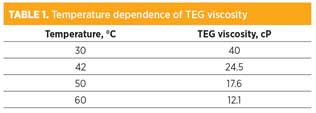 |
The only way to allow the second pump to handle the required flow was to lower the viscosity of the glycol, necessitating that the lean glycol be run hotter than desired, at a temperature of 50°C. On the surface, however, running the glycol hotter appears to be completely counterproductive to meeting the water dewpoint specification—at least, according to the charts.
The lean TEG water content is generally in the range of 0.8 wt%–0.9 wt% (TEG strength of 99.1 wt%–99.2 wt%). The rich glycol was in the range of 3.5 wt%–4.0 wt% water. Without stripping gas to the reboiler, the expected lean water content of TEG is approximately 1.2 wt% (98.8 wt% TEG). A chart in the GPSA Engineering Data Book1 shows that 98.8 wt% TEG is insufficient to meet the –5°C dewpoint specification. TEG at 99.2 wt% and 42°C could produce a dewpoint of –12°C, but the same solvent at the run temperature (50°C) needed to debottleneck the charge pump would be marginally unable to produce on-specification gas; the dewpoint would be only –4°C. From the charts,1 it is evident that as the lean glycol temperature increases (regardless of TEG strength), the treated gas water dewpoint will also rise.
This analysis uses the temperature of the lean solvent feed to the tower as the basis for determining the best possible moisture level in the dried gas. Using this temperature carries the implicit assumption that the temperature inside the top of the tower is equal to the entering temperature of the lean TEG. How valid is this assumption, and what does a mass-transfer-rate-based simulation indicate? The simulator used has a mass- and heat-transfer-rate-based glycol dehydration module, and proved to be an excellent tool to answer this question.
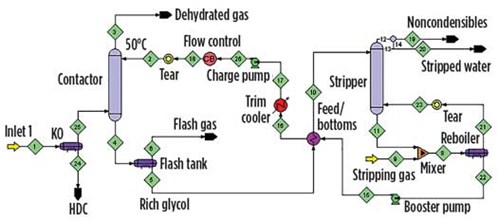
Simulation study. The flowsheet was laid out for simulation as shown in FIG. 1. Stripping gas (relatively dry methane, although not bone dry) is sparged into the reboiler by admixing with stripped solvent from the regenerator bottom. The booster and charge pumps are also shown in FIG. 1. The temperature of the lean solvent is set by the conditions in the trim cooler. The contactor contains 3.4 m of a fine-crimp structured packing. The stripper contains a random packing. The pressure in the absorber is quite high, at 10.6 MPa (106 bara). The gas is composed of mostly methane, with small amounts of C2+ hydrocarbons and a few mol% CO2.
 |
|
|
FIG. 1. A schematic of the TEG unit. |
At the initial 42°C lean TEG temperature, the simulation predicted that the lean solvent should be 99.21 wt% TEG, in perfect agreement with the measured value of 99.1 wt%–99.2 wt%. The dehydrated gas was predicted to contain 1.907 lb/MMscf of water. At the operating pressure of 106 bara, this corresponds to a dewpoint of –15°C (5°F), exceeding requirements.
The simulation was rerun with a lean TEG temperature of 50°C. The results were nearly identical to the 42°C case—increasing the lean solvent temperature by 8°C caused virtually no change in the dry-case water content, which proved to be a surprise. The simulator was then used for further experimentation over the solvent temperature range of 30°C–60°C. The results were much the same—the dried gas moisture level was unresponsive to lean TEG temperature. So, what was the determining parameter?
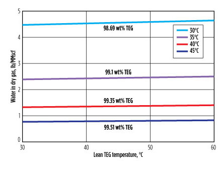
The actual temperature of the inlet gas was 38°C. Simulations were run in 5°C steps from 30°C–45°C. The results are summarized in FIG. 2. The wt% TEG shown above or below each line correlates with the temperature of the wet feed gas shown in the legend. The main observations are that the moisture content of the dried gas depends on the wet gas temperature, and it is almost completely independent from the lean glycol temperature.
 |
|
|
FIG. 2. The dependence of dried gas moisture content on lean TEG temperature. The parameter is the wet feed gas temperature and the corresponding lean TEG strength. |
This runs counter to conventional wisdom and suggests that, in this case (and in most dehydration units, as will be shown), estimating the likely dry gas moisture content on the basis of lean glycol temperature can be quite inaccurate. If one inlet stream or the other must be used, then the estimate can be made using the lean glycol water content and the wet feed gas temperature. To understand why, the mass flowrates of glycol vs. gas must be considered. In the present case, the gas-to-glycol (G:L) mass flowrate ratio was 40:1, so the gas phase completely dominates. The temperature throughout the column, including the glycol phase, is set mainly by the inlet gas temperature. It is moderated slightly by allowing for gas heating from the small glycol flow.
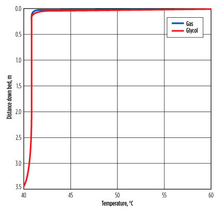
In the extremely hot case of the gas at 40°C and the glycol at 60°C, the profiles in FIG. 3 show that, within < 1 m from the bottom of the bed, the gas reached a temperature of 40.8°C and stayed at that temperature through the remainder of the packed bed. The liquid enters at 60°C and reaches 40.8°C within 60 mm–70 mm after entering the top of the bed.
 |
|
|
FIG. 3. Gas and glycol temperature changes across the column. |
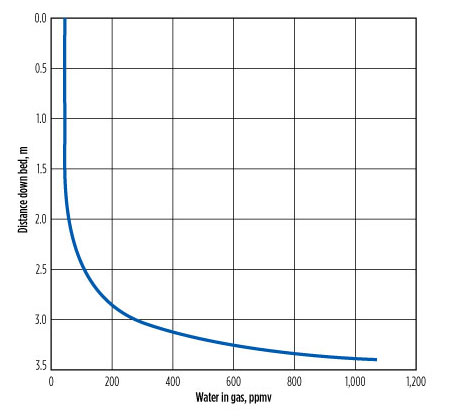
Water removal occurs over at least the bottom 2 m of the bed, where the tower temperature is not changing (FIG. 4). The average tower temperature is much closer to the inlet gas temperature than to the temperature of the lean glycol. The upper part of the bed might be called the “design margin.” It is recommended to use the inlet gas temperature as a first approximation, and the temperature found by combining the two inlet streams to find the mixture temperature for a more accurate assessment. To use only the lean glycol temperature is a poor approximation.
 |
|
|
FIG. 4. The water profile in gas across the column when the inlet gas |
Key learnings. Theoretically, the plant should have gone off-specification with the rise in lean glycol temperature. However, when the process is properly simulated with a mass- and heat-transfer-rate-based model, the effect of the lean glycol temperature increase is found to be far less troublesome than first assumed.
Glycol dehydration efficiency is based on the concept of dewpoint depression, which is usually measured from the lean glycol temperature and not the feed gas temperature. The lean glycol temperature has always been considered very important for plant performance. According to the simulation work, the treated gas dewpoint should change minimally (perhaps only within a single degree) between the 42°C and 50°C lean TEG temperatures.
The reason for the miniscule effect is seen through the gas and glycol temperature profiles across the structured packing in the absorber. These values are completely identical, except for the upper 60 mm–70 mm of packing, which is effectively operating as a heat exchanger. The liquid is cooled within the first tens of millimeters of packing, giving a profile in which variability of the lean glycol temperature is barely visible in the graphs.
In this case study, even though the lean TEG temperatures differ by 20°C, the much higher mass flow of colder gas cools the TEG dramatically to a constant, nearly feed gas temperature almost immediately. In effect, the tower is dehydrating at essentially the temperature of the gas, regardless of the lean glycol temperature.
It should also be noted that the higher the gas pressure, the lower the water content at saturation will be, and the less glycol per unit volume of gas will be needed for dehydration. High G:L ratios mean that the inlet gas will dominate and determine the absorber temperature. Dehydration is usually (but not always) carried out on gases at high pressure. The higher the pressure, the less water per unit of standard gas volume exists at saturation.
Alternatively, warm gases at low pressure can have high water content, so the G:L ratio needed to dehydrate to a high level of dryness may not be large at all. How well the feed gas temperature predicts the maximum possible extent of dehydration depends on the G:L ratio, but lean glycol temperature is probably not the best basis for conducting such a calculation. The correct temperature to use is undoubtedly the mixing cup temperature of the combined wet gas and lean glycol streams. Using the wrong temperature can have significant consequences in terms of deciding the correct strategy to overcome operational problems. Beyond estimating, however, the best tool for determining the optimum way forward is mass-transfer-rate-based simulation. Rate-based simulation takes all important factors into account, adhering to rigorous scientific and engineering principles.
In the context of this case study, the best way to keep dewpoints low is not to cool the gas (an expensive proposition, at best), but to increase the stripping gas flow to the reboiler at the regenerator, provided the stripping gas can be properly handled once it leaves the system (possibly as a fuel gas, or by flaring). Raising reboiler temperature is also effective, although approaching the degradation temperature of the TEG (206°C) must be avoided. GP
NOTES
a The simulation tool used in this study was the ProTreat simulator.
LITERATURE CITED
1 Gas Processors Association, GPSA Engineering Data Book, 12th Ed., Figs. 20–68, pp. 20–34, Tulsa, Oklahoma, 2004.
 |
Mike Sheilan is a chemical engineer with 35 years of varied industry experience. He has been involved in all aspects of natural gas processing, primarily focused on the processes and chemicals used in gas treating. Mr. Sheilan has provided expert advice, training and consulting services in the areas of hydrate control, gas dehydration, gas and liquid sweetening, hydrocarbon recovery and sulfur plant operations. He has been published in numerous industry journals and has presented at various conferences, including LRGCC, GPA, NACE, SOGAT and AFPM.
 |
Ralph Weiland is president of Optimized Gas Treating Inc., which he formed in 1992. With Australian colleagues, he developed the ProTreat mass-transfer-rate-based gas treating simulator. Dr. Weiland holds a PhD in chemical engineering from the University of Toronto, and was a post-doctorate student in applied mathematics at the University of Western Australia.


Comments