Improve gas distribution networks with innovative pipeline monitoring and repair
S. Sahajpal and A. Sircar, Pandit Deendayal Petroleum University, Gandhinagar, Gujarat, India
The natural gas distribution industry—in India, referred to as the city gas distribution (CGD) industry—caters to domestic, commercial and industrial customers. Gas supply can come in the form of piped natural gas (PNG) and compressed natural gas (CNG). The distribution system includes gas distribution mains and service lines. The pressure is regulated in the system and is usually designed as a closed-loop system to ensure uninterrupted gas supply.
The Indian government is encouraging technological advancements in the CGD sector through policies, subsidies, regulations, innovations and design modifications to existing infrastructure. Recent innovations in the CGD industry in the areas of pipeline technology, leak detection, IT application in CGD, dispensers and other equipment are discussed here.
Prominent challenges to innovation in the gas distribution sector include high operating costs due to aging assets, customer dissatisfaction due to costly intrusive pipes, third-party damage to pipes and faulty meters. Understanding the latest advances in pipeline leak detection using smart techniques, robotic sensors, CNG dispensers, filling systems and other innovative equipment is paramount to making progress in the CGD sector.
Nylon polymer piping is being used to withstand high operating temperatures. The use of ultrasonic technology is also being employed to improve weld quality in pipelines, while leak detection and pipeline inspection and repair are being improved with the help of robots, smart tools and innovations in flowmeters. Advances in CNG filling systems and dispensers are other recent developments.
Pipeline technology innovations
Nylon polymer. Nylon polymer pipe can be used to substitute for high-density polyethylene (HDPE). These new pipes can tackle low pressures of 100 psi and are available in diameter sizes of 3 in., 4 in. and 6 in. They come coiled in up to 650-in. sections.
Nylon pipe is nylon 6-based monolithic pipe developed specifically for the upstream and midstream gas industries. Nylon pipe offers 25 times more abrasion resistance and better resistance to static build than HDPE pipe. It performs in temperatures up to 90°C and has a maximum operating pressure up to 35 bar (500 psi). Typical installation time is much lower than that needed to install other pipes.
Integrated approach to welding. Ensuring long-term pipeline integrity is important during pipeline construction. Since welding is a widely adapted approach for joining steel pipelines in the CGD industry, it is prudent to have high-quality welds. Due to lower welding time, gas metal arc welding (GMAW) has been commercially used for joining steel pipelines for more than 60 yr. In GMAW, an electrical arc is maintained between the sections of steel pipeline (base material) and an electrode (filler metal). The arc heats the steel sections, causing them to melt and join. A shielding gas (usually a semi-inert gas, such as CO2 or H2) is used to protect the welding process from contaminants in the surroundings.
Traditionally, girth welds were inspected by radiography. However, radiography is limited by factors that include radiation hazards, poor detection of planar defects, safety issues and environmental concerns.
Automated ultrasonic testing (AUT) has become one of the most popular methods for inspecting pipeline girth welds. The AUT process eliminates the radiation hazards associated with radiography, and does not use chemicals. Traditional AUT technique employs the same high-frequency sound wave principles that are applied to conventional ultrasonics. Probes are used to focus beams of ultrasound onto the welds.1 They detect the reflected energy from a lack of fusion at the weld. AUT is commonly applied in inspections of longitudinal and circumferential welds on steel pipelines.2
For high-quality welds, it is important that the integration of GMAW, AUT and alternative weld flaw acceptance criteria be based on the principles of an engineering critical assessment (ECA).3 ECA is a defect acceptance criterion based on the fracture mechanics principle.4 Sophisticated software is used for flaw assessment of pipeline girth welds during reeling installation.5
Most of the time, these three techniques are addressed separately by outside parties. Each of these elements is vitally important to welding productivity and quality. A coordinated approach for integrating the three techniques will be a boon to the gas pipeline industry.
Repair of operational pipelines: Use of robots. A new robotic system for inspecting and repairing live gas pipelines from the inside has been developed in the UK. The innovation consists of two complimentary robots: one robot carries out inspection, collates data on the internal condition of the pipes, monitors corrosion level, wall thickness and stress on the pipe; and the other robot conducts repairs by injecting sealant into the walls and joints of the piping. This innovative robotic system can repair hundreds of meters of gas mains while minimizing disruption to customers.
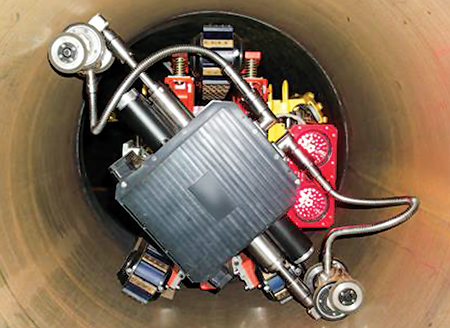
Robotic inspection of inaccessible pipelines. Robotic crawlers have made inspection of inaccessible or unpiggable pipelines possible (Fig. 1). The robotic crawlers can be navigated through a vertical section, a horizontal tee, multiple back-to-back bends with elevation changes; and many other typically difficult geometries.6
 |
|
Fig. 1. A typical inspection robot inside a pipeline. |
The crawlers use three tank-like tracts—two at the bottom of the tool for primary propulsion, and a third, upper track that extends outward to stabilize the tool in difficult geometries. Robotic crawlers are being installed with video cameras to create a record of pipeline interiors. Electromagnetic acoustic transducers and laser gauges are also installed to measure pipeline wall thickness and for contouring the pipeline interior, respectively.
Pipeline leakage detection innovations
Acoustic leak detection technology. A leak is a flaw that indicates a pipeline will eventually fail. A Canadian company introduced leak detection technology that uses the principle of sound for pipelines of a diameter of 4 in. or larger. The tool detects anomalies associated with leaks in a pressurized pipeline. These anomalies differ from others that are created by other sounds and pipeline features.
The tool is made of an aluminum alloy that consists of an acoustic sensor, a tri-axial accelerometer, a tri-axial magnetometer, a geographical positioning system (GPS)-synchronized ultrasonic transmitter, and a temperature/pressure sensor. It has a long battery life, which enables the inspection of longer distances in one deployment. It can also detect pinhole leaks and small leaks as low as 0.11 l/min, and it moves quickly and easily through pipelines.
The tool is deployed into the flow of a pipeline, traverses the pipeline, and is captured at a downstream receiver. The recorded data is aligned with the acoustic recordings to give a precise location of any recorded anomaly.
Use of dogs. Most leak detection methods (i.e., aerial surveys, optic fibers, acoustic monitoring, etc.) have significant drawbacks, including high retrofit costs and poor location accuracy. Results gathered during research on the feasibility of using dogs for leak detection verified and quantified the dogs’ accuracy and reliability in locating a leak on a pipeline. The results confirmed that a dog is 96% reliable in detecting leaks as small as 0.07 ml (an amount that is usually undetectable by conventional methods).
Inspection canines are trained to detect single target scents or multiple target scents. They can pinpoint the area of highest concentration of leaking gas. The scent of escaping or stagnant gas is easily detected by the inspection dog, along with the exact location (±0.1 m). The dogs can detect gas escaping from pipelines buried up to 31 in. below the surface, and are capable of inspecting up to 5 km/d of pipeline.7
Robotic wireless in-pipe leak detection system. Traditional leak detection systems are sometimes slow and unable to detect leakage of a lower magnitude. The present trend in the gas industry is the use of robots for detecting in-pipe leakage.8 These robots can detect leaks at a rapid pace and with high accuracy.
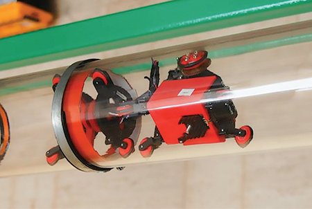
The operating principle behind these robots is detecting leaks by sensing a pressure gradient close to leak openings, thereby providing pinpoint accuracy. These robots consist of two parts: a small robot with wheels to propel it through pipes, and a drum-like membrane that forms a seal across the width of the pipe. When a leak is encountered, gas flow distorts the membrane, pulling it slightly toward the leak site. This distortion can be detected by sensors, and the information is sent to the central control system.
Reliable and inexpensive force transducers are used in these robots. The pressure gradient near the leak position is transformed into a force that is sensed by the transducers. The major advantages offered by these systems include reduction of cost, improvement in the reliability of the sensing system, and reduction in the amount of data to be processed (and, therefore, a reduction in the amount of power consumed). These robots are compact in size and can fit inside pipe diameters as small as 4 in. Fig. 2 shows a prototype of a leak-detection robot being tested in lab-scale pipe.
 |
|
Fig. 2. Prototype pipeline leak-detection robot being tested in lab. |
Application of information technology
Gas modeling software. Gas distribution network modeling and operational challenges are solved using specialized software. This software models and optimizes gas distribution and transmission networks, aiding in design, planning and operational decisions.
Analysis is performed for a closed-conduit network of pipes, regulators, valves, compressors, etc. Hydraulic framework can be analyzed at various temperature and pressure conditions, and can easily handle 1,000,000 or more nodes. The software can also add SCADA connectivity to network analysis and transient modeling.
GIS for gas distribution systems. Geographic information systems (GISs) have found a wide application in CGD systems. GISs can help prepare thematic layers of building construction, pipeline network, third-party cables, etc. These systems are also used in CGD networks for giving directions for searching pipelines, for regulating equipment and for valve-in welds. When pipelines leak or burst, the GIS dynamically displays the problem and provides a real-time decision.
CGD companies across the world are adapting GISs to support their functions. Available capacity, pressure and inlet quantity of gas at a station can be easily monitored by GIS. With recent advances in web applications and the adoption of broadband networks, it is now possible to integrate GISs with other business processes.
GISs can also assist in leak detection. Information can be gathered regarding construction material for piping, diameter, operating pressure, leaks on pipes and their repair and maintenance history. GISs can also interact with pipe corrosion detection systems and show unprotected and exposed pipes in an area.
Other innovations
Thermal mass flow sensors. Flow monitoring is an integral part of the gas distribution industry. Various types of flow sensors are used in the gas industry, with thermal sensors being the most prevalent. With technological advancements, it is prudent to explore innovative design options for flow monitoring to increase accuracy and optimize response times and sensor sizes.
One such innovative design is found in thermal mass flow sensors. The major reasons for newfound interest in micro-machined sensors are low power consumption, higher sensitivity to low flowrates, and ease of use with different modes of operation that have been achieved through miniaturization.9
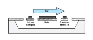
Thermal mass flow sensors are based on convective heat transfer through the gas medium, and they determine the gas velocity accordingly. Flowrate and the amount of heat transferred by the gas are interdependent factors. Thermal mass flow sensors consist of upstream and downstream temperature sensors (thermopiles) and a heater located between the two temperature sensors, as shown in Fig. 3. When the gas passes through the sensor, the heated temperature sensor is cooled by the flow of the gas. The rate of temperature change is, in turn, dependent on the flow velocity of the gas.
 |
| Fig. 3. Schematic diagram of thermal mass flow sensors. |
To keep the sensor system functioning properly, a constant temperature differential must be maintained across the sensor circuit. Heat energy from the sensor is lost due to the change in temperature of the sensor, which disrupts the circuit balance. The flowrate can be determined by calculating the magnitude of voltage compensation.10
Innovation in cascade systems. CNG is stored and filled in cascades, which are also utilized for filling vehicle onboard cylinders. Auto cascade systems are the latest innovation in the CNG filling sector.
Companies around the world have been developing design modifications to conventional cascades. The new filling systems are corrosion-resistant, have heightened accuracy and can be utilized on both stationary and cascade systems. They also feature pressure-sensing devices that provide greater accuracy without pressure drift. These systems are lightweight and compact, and can be installed on any existing filling station or wall mounting.
Innovations in dispenser design. CNG dispensers are the heart of a CNG value chain. Designers are working on innovative, easy-to-operate and robust designs for CNG dispensers. A user-friendly, robust front panel is one of the key features of new dispenser designs for quick and easy CNG filling. Some designs have hose pipes located at the center, enabling cross-filling during times of traffic congestion.
The dispensers are equipped with emergency manual shutoffs, built-in methane sensors and automatic safety controls. The flat LCD display panel and outdoor payment terminal provide maximum visibility to customers. Companies have developed new designs for dispensers that ensure seamless point-of-sale integration. These designs also have card-compliant payment technology for ease of payment.
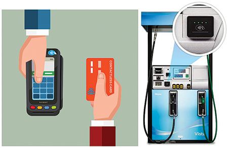
With technological advancements, a unique method of payment is being set up at fueling stations through contactless/near-field communication readers (Fig. 4). This mobile wallet and contactless technology will replace conventional credit card payments in the near future.
 |
|
Fig. 4. Contactless/near-field communication reader. |
Takeaway. Innovation is simply the power of integration. This work covered several recent innovations in the gas distribution industry. With greater advancements in technology and automation, it is becoming easier to integrate and innovate. Researchers around the world are developing new ideas in the pipeline sector for metering, fuel dispensing, welding, leak detection, pigging, etc.
The automation industry has offered innovations to the gas distribution industry in the form of smart robots. The use of robots in leak detection, pigging and repair of pipelines is improving pipeline safety and profitability.
The sector is also witnessing the use of simulation and control software for pipeline integrity management and the upscaling of real-field scenarios. The ever-growing global gas distribution industry can benefit by implementing these innovative technologies and equipment on their own, or in conjunction with one another. GP
ACKNOWLEDGMENT
The authors acknowledge the support provided by Gujarat Gas Ltd. for assistance in conducting CGD research and for granting an in-field experience to the authors.
LITERATURE CITED
1Gross, B., T. Connelly, H. van Dijk and A. Gilroy-Scott, “Flaw sizing using mechanized ultrasonic inspection on pipeline girth welds,” NDT.net, Vol. 6, No. 7, July 2001.
2Ginzel, E., “Automated ultrasonic testing of pipeline girth welds,” Eclipse Scientific, 2nd Ed., 2015.
3Horsley, D., J. Ma, C. Wassink, J. Van der Ent and M. Fingerhut, “An integrated approach to welding, AUT and ECA for pipeline construction,” International Pipeline Conference IPC 2014, Calgary, September 2014.
4Lee, K., “Reducing pipeline construction costs with girth weld ECA,” Pipeline & Gas Journal, September 2008.
5Permana, I., “A study on engineering critical assessment (ECA) of subsea pipeline girth welds for reeling installation,” Master’s Thesis, University of Stavanger, Norway, June 2013.
6Lacatena, S., “Robotic inspection of unpiggable piping at pump station,” Pipelines International, March 2015.
7Kerrigan., B, “Barking up the right tree with an innovative pipeline leak detection method,” Pipelines International, September 2012.
8Chandler, D. L., “A new way to detect leaks in pipes,” MIT News Office, June 19, 2014.
9Choi, J. C., J. K. Lee and S. H. Kong, “Fabrication and characteristics of micro-electro-mechanical-system-based gas flow sensor,” Journal of Sensor Science and Technology, Vol. 20, No. 6, 2011.
10Kuo, J. T. W., L. Yu and E. Meng, “Micromachined thermal flow sensors—A review,” Micromachines, 2012, Vol. 3.
 |
Shreya Sahajpal teaches at the School of Petroleum Technology at Pandit Deendayal Petroleum University (PDPU) in Gujarat, India. She is a chemical engineer with a post-graduate degree in chemical process and plant design. Prior to joining the School of Petroleum Technology, she worked as visiting faculty with Nirma University and PDPU. Ms. Sahajpal has worked with Larsen & Toubro Ltd. as a process engineer in the engineering and design of hydrocarbon processing units. She has published several research papers in national and international peer-reviewed journals and international conference proceedings. Her specialization is in process equipment design and process plant simulation. She has been teaching a detailed course on gas distribution at the School of Petroleum Technology for the last two years, and conducting extensive research in the area of gas distribution for the last three years.
 |
Anirbid Sircar is Director of the School of Petroleum Technology at Pandit Deendayal Petroleum University in Gujarat, India. He holds an integrated master’s degree from IIT Kharagpur. He also completed his MTech degree in petroleum and his PhD in reservoir tomography from ISM Dhanbad. Dr. Sircar received a gold medal from ISM Dhanbad for his outstanding work during his MTech degree. Additionally, he earned a PG diploma in business administration from Annamalai University. He has worked for companies like Jubilant Group, L&T Oil and Gas, Tullow and Prize Petroleum Co. Ltd. He has authored several technical papers in national and international journals. Dr. Sircar has also been conducting extensive research in the area of gas distribution for the last three years.


Comments