Engineering approach optimizes process design, reduces costs for NGL facility upgrade
M. F. Khan and R. Riaz, Jacobs Zate, Al Khobar, Saudi Arabia
In the present oil and gas market, companies may think twice before installing new equipment, even for necessary upgrades. Cost-effectiveness has become increasingly necessary. The role of the engineering contractor is critical to studying cost-reduction options during engineering design and budget allocation decisions.
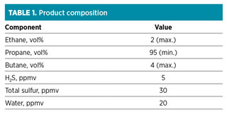
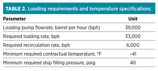
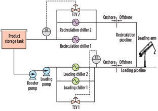
In every NGL facility, a product chiller package (PCP) is installed to subcool NGL to compensate for the subsequent heat gain in loading and recirculation lines. Subcooling of NGL guarantees that product temperature specifications for ship loading are met (Tables 1 and 2). The loading system comprises storage tanks, booster and loading pumps, loading and recirculation chiller packages, a loading pipeline, a recirculation pipeline and offshore loading arms. To keep the NGL product subcooled and ready for ship loading, it is continuously recirculated from the loading area back to the storage facility, with recirculation chiller packages installed upstream of the storage tank (Fig. 1).
 |
|
Fig. 1. Propane storage and loading system. |
System upgrade study. A study was performed to upgrade the existing product loading facility (PLF) to enhance operational reliability and conformity to client standards and product specification. Primary objectives of the study included:
- To replace existing PCP refrigeration system compressors that do not comply with API 617 (axial and centrifugal compressors and expander compressors), as these compressors were primarily designed for industrial chilling units and then reused as refrigerant compressors of the PLF refrigeration system. This inherent design deficiency causes frequent leakage of freon refrigerant (R-22) to the atmosphere.
- R-22 refrigerant is chlorodifluoromethane, generally known as hydrochlorofluorocarbon (HCFC). Environmental regulatory authorities in different countries—including the US, Australia, Canada and Saudi Arabia—plan to completely phase out its industrial use. To comply with environmental regulations, R-22 must be replaced with R-507.
- Based on an earlier evaluation, it was concluded that retrofitting the existing PCP is technically unfeasible by replacement of only the existing compressors. The reason for this is that existing chilling units were designed for use with R-22 refrigerant. The use of R-507 refrigerant in lieu of R-22 would necessitate new process design conditions that would require replacement of all vessels, equipment and the interconnecting piping system associated with the chilling units.
System description. The existing PLF consists of four product storage tanks, PCP (two loading and two recirculation chillers packages using R-22 refrigerant), two loading pumps and, 11-km low-temperature carbon steel (LTCS) loading and recirculation pipelines.
During normal operation, one of the two loading chillers and one of the two recirculation chillers remain in operation to subcool the product flowing to the offshore loading arms and to liquefy/subcool the recycle flow returning from offshore. A second loading chiller may be put into service, depending on loading requirements.
Loading and recirculation pipelines may be exposed to the minimum design metal temperature (MDMT) of –50°F due to excessive subcooling in the PCP. For this reason, temperature control valves (TCV) are provided across loading and recirculation chillers to bypass part of the flow in case of low outlet temperature, as shown in Fig. 1. The CV of each TCV at 100% opening is equal to the design product flowrate of a single chiller. During normal operation (i.e., auto control mode), TCV-1 and TCV-2 remain fully closed.
System optimization. In addition to achieving the primary design objective of new chillers for R-507 refrigerant service, the PLF has been further studied to capture other design optimization opportunities in the existing process. The system has been simulated in a proprietary process simulator, from the storage tanks to the loading arms. Worst-case scenarios (i.e., maximum summer ambient temperature, maximum and minimum product loading flowrates, etc.) were considered.
After a detailed analysis of the PLF, the following system optimization objectives were selected for further detailed evaluation:
a. Reduce heat losses in the loading/recirculation pipelines
b. Reduce PCP design heat load.
The basis for the process simulation model development is:
- Maximum ambient temperature of 108°F
- Maximum product loading flowrate of 33,000 bph
- Minimum product loading flowrate of 4,000 bph
- Maximum pump outlet temperature is taken from the pump data sheet
- PCP outlet temperature is fixed at –48°F due to pipeline MDMT constraints
- Required loading temperature and pressure are the same as the product loading specification (see Table 2)
- Insulation material, thickness and thermal conductivity are considered to be the same as the available design data (see Table 3)
- Wind velocity of 2.2 m/sec is taken as per site data.
Objective a: Reduce heat losses in loading/recirculation pipelines. To minimize PCP design duty, the first option is to reduce the heat losses in the 11-km loading and recirculation pipelines. Heat losses could be minimized by using a high-grade insulation material, or by increasing the insulation thickness of the existing product pipeline.
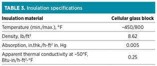
The maximum allowable heat gain is calculated for the pipelines, and the insulation thickness is calculated based on the site’s most unfavorable ambient conditions in summer, using the data listed in Table 3. The results showed that the existing insulation material is of premium grade and the insulation thickness is the same as that calculated in the simulation model.
Objective b: To reduce PCP heat load. In the simulation, two cases were modeled and studied. Maximum and minimum loading flowrates for evaluation were:
- Maximum loading (33,000 bph loading + 6,000 bph recirculation)
- Minimum loading (4000 bph loading + 6,000 bph recirculation).
Design objective. According to the original design basis, two chiller packages have been dedicated for loading, while two packages have been dedicated for recirculation service. Loading requirements cannot be achieved with this configuration.
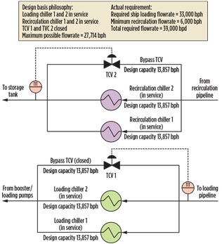
As per Table 2, the capacity of each chiller is 13,857 bph. The total capacity of two chiller packages is 13,857 × 2 = 27,714 bph. The third chiller should be put into loading service to meet the loading requirement at 33,000 bph, as per Table 2. This scenario leaves no spare chiller in case of an (emergency) outage of any of the in-service chillers (Fig. 2).
 |
|
Fig. 2. By placing two loading chiller packages into service, |
Scenario 1 considers two chiller packages in loading service while bypassing the remaining flow. Product temperature remains within the contractual requirement (–41°F). Results are presented in Table 4.

Scenario 2 considers only one chiller package in loading service while bypassing the remaining flow. Product temperature remains within the contractual requirement (–41°F). Results are presented in Table 5.

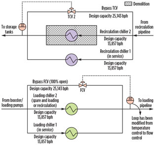
Proposed modifications. With the support of simulation results, modifications were proposed in the existing design, whereby one PCP was eliminated while still meeting design objectives. The major modification necessary to make the system operate (with three PCPs) was to change the TCV-1 to an FCV so that flow could be adjusted to suit loading requirements. Under normal and maximum loading rates, the FCV could provide flow as listed in Table 5.
To meet all loading requirements and product specifications, additional changes were proposed for the loading and chilling system:
- Reduce number of PCPs from four to three
- Modify Loading Chiller 2 inlet/outlet piping to be used as loading/recirculation chiller
- Change the bypass TCV-1 to an FCV with a capacity of 25,143 bph
- Increase the flow capacity of TCV-2 to 25,143 bph.
Implementation of the proposed changes is shown in Fig. 3.
 |
|
Fig. 3. Proposed chiller system changes. |
Benefits of proposed changes. The results of this case study supported elimination of one PCP without compromising design ship loading rates and the (contractual) loading temperature specification. The issue of low temperature was solved by allowing maximum flow to pass through the bypass control valve without chilling. The estimated chiller package and construction cost savings resulting from the proposed changes are approximately $14 MM.
The original project scope was to replace four existing PCPs with four new PCPs to increase system reliability. However, this case study supported the idea of saving costs in a critical process area by reducing the number of key pieces of equipment from four to three. The results of this case study ultimately led to a more efficient and cost-effective upgrade. GP
ACKNOWLEDGMENT
The authors thank their colleagues, Muhammad Farooq Ghilzai, Ganesh Shetty and Noor ul Haq for their valuable comments and suggestions during the review of the draft article.
LITERATURE CITED
- American Petroleum Institute, “API Standard 617: Axial and centrifugal compressors and expander-compressors,” 8th Ed., September 2014.
- Wikipedia, “Chlorodifluoromethane,” September 2016, https://en.wikipedia.org/wiki/Chlorodifluoromethane
 |
Muhammad Farooq Khan is a process engineer at Jacobs Zate in Al Khobar, Saudi Arabia. He worked with Attock Refinery Ltd., SMEC Oil & Gas Ltd. and Olympia Chemicals Ltd. He has seven years of experience in refinery operations, chemicals, and oil and gas design in onshore, NGL processing, refining and gas-oil separation plants. He has also been involved in several refinery in-house research projects. Mr. Khan earned a BSc degree in chemical engineering from the University of the Punjab in Lahore, Pakistan.
 |
Rehan Riaz is a process engineer at Jacobs Zate in Al Khobar, Saudi Arabia. He has nine years of experience in detailed design engineering, front-end engineering design and plant operation for oil, natural gas, petrochemical and ammonia plants. He has an MSc degree in chemical engineering from the University of Engineering and Technology in Lahore, Pakistan. Previously, he worked for Worley Parsons Ltd. In Saudi Arabia.


Comments