Manage activated carbon effects on MDEA solution foaming
D. Engel, S. Williams and A. Heinen, Nexo Solutions, The Woodlands, Texas
In the oil and gas industry, activated carbon (AC) is used in many applications, both as an adsorbent and as a support media for chemical reagents. One of the most common uses is in amine units. The occurrence of foaming episodes in amine units is perhaps the single most common problem leading to operational losses. The AC has the function of removing soluble contaminants from the amine solvent, thereby reducing foaming tendency. However, no systematic study exists of the relative effect of AC adsorption with respect to foaming reduction in amine solutions.
The work in this article focuses on the contact times and amounts of AC affecting contaminated methyldiethanolamine (MDEA) amine solutions, and the effect on foam stability and foam-reduction (break) kinetics. The work was carried out using contaminated MDEA samples from a US refinery with considerable foam stability.
The results indicate that contact times of at least 15 minutes (min) are necessary for proper foam reduction and solvent cleaning. Increasing proportions of AC were also found to reduce foam tendency, with an almost linear correlation up to 50 wt%. Surface tension experiments also confirm that contaminated MDEA samples, with stable foam formation, can be purified to a state that is nearly foam-free after proper treatment with AC.
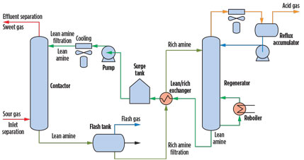
Gas treating and amine units. Amine units are employed in gas processing plants and petroleum refineries to remove acid gases (H2S and CO2) from gas streams, liquefied petroleum gas (LPG), recycled gases and refinery offgases. An amine unit is also used in CO2 sequestration, metals production and syngas production, among others. The amine unit (Fig. 1) generally consists of an absorber or contactor tower, a regenerator tower and ancillary equipment, such as heat exchangers, filtration systems, pumps, valves and instrumentation.
 |
|
Fig. 1. Process flow diagram for a typical configuration of an amine unit. |
The active liquid medium in an amine unit is an alkanolamine solution (i.e., methyldiethanolamine), typically in a 20%–50% concentration in water. The amine solution recirculates within the unit. In the absorber, the lean amine solution reacts with the H2S and CO2 via direct or indirect reactions and absorbs H2S and CO2 from the gas stream (known as sour gas) to produce a sweetened or treated gas.
The rich amine solution, high in H2S and CO2, exits the absorber at the bottom of the absorber tower. The rich amine solution is routed into the regenerator, generally passing through a flash tank to reduce the pressure and remove offgas and light hydrocarbon, if present, and a heat exchanger to heat the rich amine and cool the regenerated lean amine stream.
The regenerator reverses the reaction that took place in the absorber and strips the H2S and CO2 from the amine solution. The stripped gases are then sent to a number of processes for proper disposal or recovery. The stripped lean amine solution is sent back to the absorber after cooling and conditioning with filtration and AC adsorption.
The main chemical reactions taking place in the amine unit are:
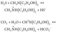 (1), (2)
The amine unit is a high-efficiency system that operates under stringent specifications, and any downturn in performance can lead to products out of specification, solvent losses and high operational costs. Contamination in amine units is very detrimental to plant operations. To enable processing plants to run with minimal instabilities, increased capacity and high reliability, it is necessary to condition process streams using proper contamination control methods. A variety of new and old technologies can remove certain contaminants efficiently; yet, the complexity and misinformation associated with many removal options have led to disconnect among the needs of end users, recommendations from suppliers and specifications from engineering companies.
Proper knowledge of feed gas and amine treating systems is a vital component of unit design and operation. Feed gas should be conditioned to remove solid and liquid contaminants before it enters the amine absorber, and recirculating amine streams should also utilize correct filtration and coalescing technologies. Lean amine streams, in particular, must be conditioned by filtration, as well as by AC adsorption before re-entering the amine absorber to prevent foaming, fouling and a number of other problems. AC adsorption removes dissolved contaminants from the amine stream and is a critical—yet often overlooked—system for efficient and reliable amine unit performance.
AC adsorption. AC is an inert solid adsorbent material commonly used to remove a number of dissolved contaminants from water and process fluid streams. AC is a porous, inexpensive and readily available adsorbent that provides a large surface area for contaminant adsorption. It is an extremely effective material for dissolved contamination removal related to color, odor and foam-promoting species, among others.
The removal process takes place via an adsorption phenomenon based on surface interactions of the contaminant and the C grain surface. The interactions occur by weak and reversible Van der Waals forces and dipole-dipole forces. As a result, the separation is generally effective for organic components. It is important to mention that AC beds are not intended to be used as filters for suspended solids removal or for the removal of emulsified liquids. The operation of an AC bed is specific to removing dissolved contaminants only. Therefore, AC beds should not display any meaningful differential pressure increase across the bed.
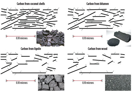
The properties of AC are associated with the source of the C and its configuration (Fig. 2). Several different origins of AC exist with inherent properties, such as pore structure and size distribution, as well as different sizes and production methods.
 |
|
Fig. 2. General schematics of the different types of ACs showing their associated |
AC can be made from coconut husks, lignite, coal, bitumen and wood, among others. The source will determine both the adsorption capacity and the size distribution of the contaminants it can adsorb. As far as configurations, the AC can be powder or granular (most common in amine units), or extruded in forms such as blocks and pellets.
AC bed systems are commonly used to remove impurities so that the amine solution can be properly utilized for effective contaminant removal. If the impurities are not properly removed from the amine solution, then foaming, corrosion and other problems may occur in the plant, leading to considerable negative technical and economic effects. In general, AC of the bituminous type is chosen for amine units because of its balance of small, medium and large pores within the C grain. This distribution is often the most suitable for amine streams with a wide distribution of molecular-size contaminants.
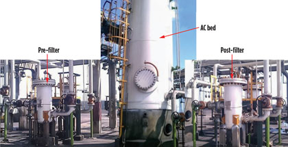
A typical AC bed system is shown in Fig. 3. The vessel arrangement comprises a pre-filter for protecting the bed from suspended solids, the AC bed itself, and the post-filter for capturing the C fragmentation residues. In general, the AC system is installed in the lean amine circuit after cooling. Processing into the bed is usually anywhere from 10% to 50% of the total amine flow; a minimum of 25% of the total flow is recommended. As far as design is concerned , most C beds are vertical in orientation with a top-to-bottom flow and a minimum of 15 min residence time.
 |
|
Fig. 3. A typical lean amine AC adsorption system with pre-filtration and |
To better understand the functionality of AC, a series of experiments were performed to measure its effectiveness in removing impurities that primarily cause foaming of the amine solution. Contaminated MDEA samples with stable foam formation were used for the experiment. The amine solution was taken from a US Gulf Coast refinery. Additional experiments were also performed with the objective of determining any potential correlation between the amount of AC that an amine solution is exposed to, and foaming tendency.
It is important to note that it was not the intention of the work to mimic the exact conditions in an amine unit, as this would pose considerable challenges in a laboratory scale. The testing that follows was performed under controlled laboratory conditions that resemble the unit operation and allow for correlations to be concluded.
Materials and methods. Ten 20-mL glass vials were used to contact the contaminated lean amine with bituminous AC (8 × 30 mesh). Eight of the vials contained 1.5 g of AC, and the other two vials did not contain any C.
The eight vials with the C were then mixed with 15 mL of the lean MDEA amine solution. The MDEA in each vial was in contact with the C for different increments of time (5 min, 10 min, 15 min, 30 min, 1 hr, 2 hr, 4 hr and 8 hr). The amine was then filtered into a clean vial to completely remove the AC from the amine. The ninth vial contained 15 mL of the contaminated lean MDEA that had not been exposed to the AC, and the tenth vial contained pure MDEA at 50% in distilled water.
The 10 vials were then lined up on a shaking rack (Fig. 4). The rack was mechanically shaken in a consistent manner for 90 sec to impart energy for foam formation. Pictures were taken at 10 sec, 30 sec, 1 min, 2 min, 5 min, 10 min, 30 min and 1 hr after shaking was ceased. Control samples of the untreated MDEA solution and a pure MDEA in water (50%) solution were also included in the test, analyzed for their interfacial tension and compared.
 |
|
Fig. 4. Shaking rack set up before agitation. |
Once the shake-induced foam test was completed, a second experiment was performed to understand potential effects on foaming as the amine was contacted with increasing amounts of C. Five different samples were made by soaking 15 mL of the MDEA in 0 g (0%), 0.75 g (5%), 1.5 g (10%), 3.75 g (25%) and 7.5 g (50%) of AC. The MDEA and AC were contacted for 20 min, and the amine was then filtered to remove any C residues. The vials were then subjected to the shake-induced foam test for 90 sec. Pictures were taken after 10 sec, 30 sec, 1 min, 2 min, 5 min, 10 min, 30 min and 1 hr after shaking was ceased. Control samples of the untreated lean MDEA solution and a pure MDEA (50%) solution were also included in the test, analyzed for their interfacial tension and compared.
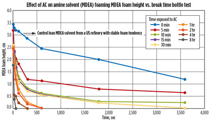
Results. After the shake-induced foam was completed, the pictures were evaluated and the foaming height was measured using computer software. The foam height over time was then plotted (Fig. 5), using the pictures taken. The graph shows the foaming tendency and foaming stability of nine of the 10 vials. The tenth vial, pure MDEA, did not show any foaming tendency.
 |
|
Fig. 5. Graph showing the effect of AC on a lean amine solution. |
Fig. 5 shows that the longer the contaminated lean amine solution was contacted with AC, the more rapidly the foaming was reduced. Although the foaming was never completely removed, a substantial difference in the amount of foaming reduction over time was seen as the amine solution was contacted with AC.
It could also be observed that contact times of 10 min, 15 min, and 30 min gave similar results. Increasing the contact time increased the foam-reduction kinetics. Extended contact (8 hr) of the contaminated MDEA with AC eliminated foaming in 30 sec, while the untreated contaminated MDEA displayed foam for up to 4 hr. As part of amine unit best practices, it is recommended that the contact time of an amine solution be a minimum of 15 min, consistent with the above obtained laboratory data.
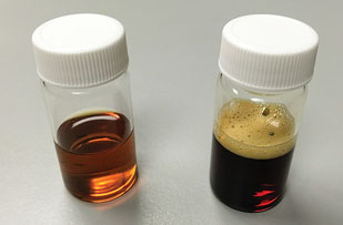
Fig. 6 shows a marked color change from the contaminated lean MDEA that was not exposed to AC, as compared to the vial that contained the MDEA that was exposed to AC for 8 hr. This is likely because the AC collected the impurities and clarified the MDEA solution. A change in viscosity was also observed but not measured.
 |
|
Fig. 6. Vials before (right) and after (left) contact with AC |
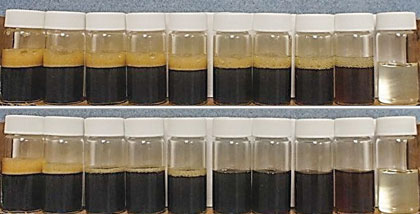
The pictures taken during testing show that foaming of the contaminated MDEA that was contacted with the AC dissipated rapidly compared to the untreated sample. This can also be observed in Fig. 7, corresponding to the experiments that generated the plot in Fig. 5. The different vials contained the contaminated lean amine contacted with AC for increasing periods of time (from right to left). The vial on the left is the untreated lean amine with the highest foam formation, and the vial on the right is the pure amine solution (50%) control that exhibits no foam formation.
 |
|
Fig. 7. Vials after shake test. The top rack shows vials 10 sec after the shake test. |
Several of the samples were analyzed for interfacial tension after the foam-induced shake test. The analysis was carried out using the pendant drop technique. The surface tension is one of the contributing factors to foam formation because it reduces the molecular interaction forces in the amine solution, enabling liquid to be released more easily from the bulk solution into the above head-space volume.
The interfacial analysis results are summarized in Table 1. As can be observed, the interfacial tension of the pure MDEA (50% in distilled water) solution is significantly higher than that of the contaminated lean MDEA sample. The lowering of interfacial tension in the contaminated MDEA sample was caused by the dissolved contaminants, surfactants and amine decomposition residues present in the solution. Upon exposure to AC, it was observed that the interfacial tension increased, but never reached the levels of the control pure amine solution.

It can be interpreted from the results in Table 1 that AC plays an important role in reestablishing the surface tension of a contaminated lean amine solution and reducing foam tendency. Extended contact times are also necessary for proper contaminant removal. The extent of increasing the interfacial tension with longer contact times seems to taper off asymptotically after 15 min, as little difference in interfacial tension was measured in samples after 5 min and 15 min of exposure to AC.
This correlation should be further confirmed by more comprehensive testing with other contact times between 5 min and 8 hr. It should also be noted that interfacial tension of the contaminated lean MDEA sample did not reach that of the pure MDEA solution (50% in water) even after 8 hr of contact time. This aspect implies that a larger proportion of AC is likely needed for complete purification.
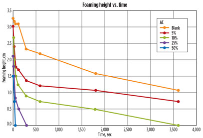
A second experiment was conducted by exposing the contaminated amine sample to different amounts of AC. After the amine was contacted with different percentages of AC, the foam-induced shake test was performed. The images from the different vials were then analyzed, and the foaming height was determined for each vial in each picture. The foaming height was then plotted over time, as shown in Fig. 8.
 |
|
Fig. 8. Graph comparing foaming height over time of MDEA soaked in different |
The graph shows that contacting the contaminated lean MDEA in increasing amounts of AC decreased foam height and eliminated foam rapidly. The foam from the sample that was contacted with 50% AC (on a weight basis) was eliminated within 60 sec. The foam on the other amine samples exposed to decreasing amounts of AC displayed a slower rate of foam reduction. This is interpreted in terms of the faster contaminant adsorption kinetics when larger amounts of AC are utilized for contacting the amine solution. Several of the samples from the above experiment were analyzed for interfacial tension. The results of these tests are summarized in Table 2. The analysis was performed using the pendant drop technique.

It can be observed from the results that increased proportions of AC in contact with the contaminated lean MDEA sample restores the interfacial tension of the sample. The extent of the increase in interfacial tension with increasing proportions of AC seems to be nearly linear. This correlation should be further confirmed by testing different samples with other proportions of AC between 10% and 50%.
The contaminated lean MDEA contacted with 50% AC was measured to have a higher interfacial tension than that measured for the pure MDEA (50% in distilled water) solution. This is probably because the contaminated lean amine solution did not have a 50% concentration in water. The concentration was likely near 40% in distilled water, which is common in amine units with liquefied petroleum gas (LPG) feed streams. Concentrations above 40% will cause excessive emulsification, leading to excessive amine solvent carryover losses.
Takeaway. The various experiments described here were run under lab conditions, but close to actual process conditions, so that correlations can be established. The data shows that AC, in fact, assists in the removal of contaminants that cause foaming and foam stabilization.
The data also shows a foam-reduction correlation between increasing contact times of the amine solution with the AC. The contaminated lean MDEA solution shows less foaming tendency as contact time increases. Contact times of 15 min (minimum) were effective in reducing foam at an acceptable rate. Foaming was never totally removed during the experiments, but a significant difference was noticed in terms of foam break times.
A correlation was also observed between the weight of AC and the foam-reduction kinetics. The contaminated lean MDEA solution exposed to larger amounts of AC displayed substantial reduction in foaming tendency compared to a contaminated lean amine that was not exposed to AC. It also resulted in an increase of the solution’s surface tension.
Results suggest that lean amine solutions contacted with ≥ 25% AC by weight will reduce foam almost completely at ambient conditions after only 5 min of contact time. On a more simplistic note, the study shows that AC adsorption plays a fundamental role in amine solvent foam reduction, and, by implication, most (if not all) amine units should properly utilize AC beds for foam prevention. GP
 |
David Engel has more than 20 years of industrial experience in a variety of technical areas. He is the inventor in 17 US invention patents and the author of a number of technical and scientific papers. Dr. Engel has developed business and technology for Eastman Kodak, Eli Lilly, Pentair, General Electric and Sulphur Experts globally. He has presented a number of seminars and technical courses on a variety of process engineering and chemistry subjects. Recently, he has specialized in advanced process systems and multicomponent separation methods for removing or mitigating contaminants in process streams. Dr. Engel is the cofounder of Sulphur Experts—Filtration Division and managing director of Nexo Solutions. He holds a BS degree in industrial chemistry and a PhD in organic chemistry. He is a member of the American Chemical Society and the Gas Processors Association, president of the American Filtration and Separation Society (Southwest Region), a GLC Consulting member, and a board member (editor) for Elsevier and Genesis BioHealth.
 |
Scott Williams is a process engineer at Nexo Solutions. He has industry experience in many projects, and has been instrumental in providing solutions in oil and gas, petrochemical, chemical and water treatment applications. As part of the engineering group, Mr. Williams is responsible for technical design and solutions development in engineering and technology applications, and he also provides support for Nexo’s analytical and specialized service projects. His latest focus is in the area of contaminant removal using novel systems and chemistries for H2S and mercaptans removal from gas and liquid streams. Mr. Williams has also recently worked on projects involving oil-based drilling mud characterization, inlet separation and coalescer evaluations, and back-washable metal-based media for NGL feed filtration systems. He holds a BS degree in chemical and biological engineering from the University of Colorado at Boulder.


Comments