
Remove mercaptans from hydrocarbon condensates and NGL streams
D. ENGEL, EXION Systems, The Woodlands, Texas; and H. BURNS and
S. WILLIAMS, Nexo Solutions, The Woodlands, Texas
Here, the removal of mercaptan components from a hydrocarbon condensate stream at a Canadian gas plant, using a novel removal chemistry and separation technology, is investigated. The removal of mercaptans was required to meet pipeline specifications for total sulfur and mercaptan concentrations. The onsite work consisted of verification of the nonregenerable chemical additive for mercaptans removal in combination with a liquid treating process separation system.
A miniaturized version of the removal process system was assembled onsite, and a 1.65-gpm slipstream of condensate was processed through the miniaturized system. Condensate samples were captured before and after treatment, and analyzed using a gas chromatograph to quantify mercaptan removal levels.
The trial results showed that removal of mercaptans (up to 95% for C1–C3, up to 90% for C1–C4, and up to 60% for C1–C7) is achievable using the combined process systems. The removal efficiency is related to the additive concentration applied and to the water wash stage.
Trial background. Gas processing often encounters problems with feedstocks containing high levels of mercaptans, which concentrate in hydrocarbon condensates and NGL when the mercaptans are not removed by the acid gas removal unit (AGRU) or molecular sieves dehydration units.1, 2
While hydrogen sulfide (H2S) and carbon dioxide (CO2) are removed by amine treating in most gas plants, the majority of amines will remove few to no mercaptans. When condensates recovered at the gas plant contain high levels of mercaptans, process deficiencies, such as polymeric fouling or amine solvent contamination, can occur. Additionally, the condensate or its fractionated products often will not meet total sulfur specifications for sales or pipeline transmission.
A gas plant near Alberta, Canada was in need of a solution for the removal of small and volatile (C1–C3) mercaptans contamination in the hydrocarbon condensate stream. The NGL (following condensate fractionation) must meet certain specifications to be transported via pipeline, and the average level of volatile mercaptans did not meet the < 175 mg/kg requirement set by the plant.
The plant, assisted by a solutions provider, researched the best possible solutions for mercaptans removal, including chemical technologies and process systems. A proprietary technologya was determined to be a potentially effective option for mercaptans removal.
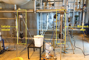
To optimize and validate the system, field optimization using a test unit was implemented. This study outlines the field optimization process and the performance of the mercaptans-removal system. The solutions provider conducted onsite testing of a slipstream of the condensate stream, using an injection of proprietary liquid treating solutionb to remove the mercaptans. A small-scale liquid treating systemc was used to apply the chemical (Fig. 1).
 |
|
Fig. 1. Test system used for mercaptans-removal |
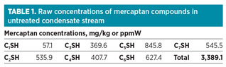
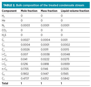
The concentrations of mercaptans in the condensate stream are shown in Table 1. Also, Table 2 shows the bulk composition of the treated condensate stream. The flow, temperature and pressure of the stream are 2 Mbpd, approximately 270°F and approximately 100 psi, respectively.
 |
 |
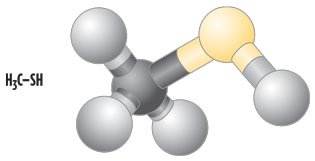
Mercaptans, or thiols, are a group of sulfur-based components that are found in many hydrocarbon streams, mainly as an impurity. Mercaptans are similar to alcohols, but with the O2 atom replaced by a sulfur (S) atom. This change confers to mercaptan molecules’ distinct chemical and physical properties. Organoleptic properties are also affected; for example, mercaptans have a particularly foul odor. The change from a more electronegative atom (O2) to S also imparts to mercaptans a more acidic character compared to their alcohol counterparts, due to the sulfur atom’s stabilizing effect. Mercaptans, however, are only slightly acidic, and this acidity is reduced as the molecular weight of the mercaptan increases. Fig. 2 shows the molecular formula and structural 3D model for one of the most common mercaptan contaminants, methyl mercaptan (also called methylthiol or methanethiol).
 |
|
Fig. 2. Molecular structure (left) and molecular model (right) |
Relative to alcohols, mercaptans are more acidic. Butylmercaptan has a pKa of 10.5 compared to a pKa of 15 for butanol. Phenolmercaptan has a pKa of 6 vs. 10 for phenol. Therefore, mercaptanate (or thiolate) salts can be created by treating mercaptans with alkali hydroxides, such as sodium hydroxide or caustic. In fact, caustic is a common removal method for mercaptans in liquid streams (water and hydrocarbons). The chemical equations for the reaction of mercaptans (R-SH) and alcohols (R-OH) with sodium hydroxide are shown in Eqs. 1 and 2:
R–SH + NaOH ∀ NaS–R + H2O (forward reaction) (1)
R–OH + NaOH 1 NaO–R + H2O (equilibrium reaction) (2)
In addition, mercaptans have weaker intermolecular forces. They show little association by hydrogen bonding with water molecules or among themselves. Mercaptans have lower boiling points and are less soluble in water and other polar solvents than alcohols of similar molecular weight. Therefore, mercaptans will have a higher equilibrium vapor pressure and will be more soluble in hydrocarbon phases. Some mercaptans are also gaseous at ambient conditions in comparison to their O2 analogues, due to their lower boiling point.
One example is methyl mercaptan (gas) in comparison to methanol (liquid). The electronic configuration of mercaptans (namely the presence of d-orbitals in sulfur atoms) provides them with high interactive properties with many surfaces, especially metals. This interaction is the basis for some common metal surface friction reducers. In many instances, S molecules can also serve as metal ion chelants and metal stabilizers.
From health, safety and process perspectives, the removal of mercaptans is often necessary. Some mercaptans present strong odors and can cause serious disruptions to daily life. Humans are highly sensitive to mercaptans at very low levels. For this reason, mercaptans are used as odorizers in consumer and commercial natural gas to signal gas leaks. Some mercaptans can cause corrosion, and often lead to copper strip test failures under certain conditions. Mercaptans can also negatively affect catalysis and solid adsorption beds, such as silica gel or alumina, by competing for access to the same active sites. Mercaptans removal is necessary for reducing sulfur emissions, as combustion and emission of mercaptan-containing compounds will lead to SOx formation.
Mercaptans removal can be accomplished through a number of methods. The most common method in use today is the reaction with caustic (sodium hydroxide, NaOH), shown earlier. Oxidation by a strong oxidant reagent, such as sodium hypochlorite (NaClO), O2 and hydrogen peroxide (H2O2), among others, has also been employed. The chemical equations for mercaptan oxidation are shown in Eqs. 3 and 4:
2 R–SH + 1⁄2O2 ∀ R–S–S–R + H2O (oxidation by O2) (3)
R–SH + 3 H2O2 ∀ R–SO3H + 3 H2O (oxidation by H2O2) (4)
Other methods for mercaptans removal from hydrocarbon streams are available and include oxidation using ozone, biological removal processes, catalytic decomposition, adsorption into solid beds (i.e., functionalized activated carbon) and specialized (e.g., physical and hybrid) solvents. Only the two latter methods are commonly used in the industry, however.
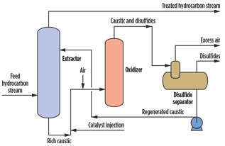
The use of NaOH for mercaptans removal is perhaps the most common worldwide. The reaction with caustic is effective, but is also a reversible equilibrium. NaOH is readily available at low cost. However, nonregenerative caustic treatment produces a waste spent caustic stream that must be treated or managed properly. Regenerative caustic treatment produces disulfide oil and a waste caustic bleed. Fig. 3 shows a typical regenerative caustic mercaptans-removal process.
 |
|
Fig. 3. General regenerative caustic mercaptans-removal |
The use of caustic for mercaptans removal creates high salt content, and, in many cases, there is odor release. In some cases, the spent or rich caustic can be regenerated using a catalytic process and O2. The O2 regenerates the rich caustic so that it can be reused in the process; however, it also produces a secondary disulfide oil (DSO) byproduct. Disulfides (also called red oil) are water-immiscible materials that can be a challenge for disposal in a gas plant. The chemical reactions for the regenerative caustic removal of mercaptans are shown in Eqs. 5 and 6 (Note: R represents the hydrocarbon group):
2 R–SH + 2 NaOH ∀ 2 NaS–R + 2 H2O
(extractor reaction with excess NaOH) (5)
4 NaS–R + O2 + 2 H2O ∀ 2 R–S–S–R
(water-immiscible DSO) + 4 Na+ + 4 OH– (regeneration) (6)
In this case study, alternative products were developed especially for mercaptans removal. The concept was to use a nonregenerative mercaptans-removal method that would not produce significant waste. This would not only minimize capital costs, but it would also reduce any posttreatment costs. The reaction pathway does not involve the use of caustic and eliminates the need for secondary treatments, such as regeneration of spent caustic or spent caustic disposal. The proprietary chemical liquid treating product is a specialized polyhydric alcohol molecule, stabilized by hydroxyl materials, that enables the removal of H2S, mercaptans and COS. The general chemical reactions for the reaction with mercaptans are shown in Eqs. 7 and 8 (Note: CA represents the chemical additive):
R–SH + CA ∀ R–S–S–R + R–S–SO–R + R–R + SO4–2 + H2O (oxidative coupling) (7)
R–S–SO–R = sulfoxide species (water-soluble and does not affect the process) (8)
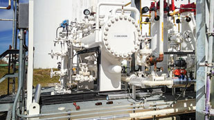
The reactions in Eqs. 7 and 8 show that water, sulfate (SO4–2) and other oxidized components are products of the reaction. The water-soluble sulfate ion is removed with separated water from the condensate. The CA is designed for use with process equipment, such as a phase separator downstream of the injection point. The solutions provider has developed specialized systems for enabling the liquid treating chemistry to operate with high efficiency and impart flexibility for its use. A picture of a full-scale liquid treating system is shown in Fig. 4.
 |
|
Fig. 4. Single-stage liquid treating system showing the |
The system features an injection point for the CA, followed by a mixing and contacting stage for mass transfer and for enabling the reaction to occur effectively. A high-efficiency water wash stage is installed downstream of the contactor. The water wash is also thought to boost efficiency because of the further contacting of any excess chemical. The mixture is then routed to an extraction stage for phase separation and byproduct removal.
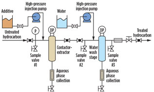
Testing methodology. The selected testing point for the condensate stream was located at the outlet of the stabilizer unit. A miniaturized liquid treating system was assembled using the same treatment configuration as a full-size system. Fig. 5 shows the schematic of the small-scale system, including the injection points for the CA and water, the valve arrangement, the contactor and extractor equipment, and the effluent streams. Contact time was set to 0.45 sec from the point of CA injection to the contactor unit.
 |
|
Fig. 5. Schematic of miniaturized liquid treating system for |
The materials used for the onsite testing include the miniaturized system; slipstream piping for the process stream; CA with water; and equipment for sampling, mercaptans detection and quantification (analyzed by gas chromatography). Sampling was done upstream and downstream of the contactor and extractor, as shown in Fig. 5.
Test conditions and procedure. The temperature of the condensate was approximately 270°F, as measured at the stabilizer outlet, and a slipstream flowrate of 1 gpm–1.65 gpm of condensate was maintained from the stabilizer outlet into the liquid treating system. The testing setpoints used were varied during testing to optimize the mercaptans-removal efficiency. A 65-mL/min injection rate (chemical/water), or approximately 1%–1.7% of the total condensate flow treated, was generally utilized.
A water usage rate of 1%–2% of the condensate flowrate was maintained throughout testing to ensure adequate mixing and contact between the chemical and contaminants. The chemical/water injection was at room temperature (21°C). Samples were taken for analysis after the contactor and after the extractor, using specialized “piston cylinders” to maintain sample integrity.
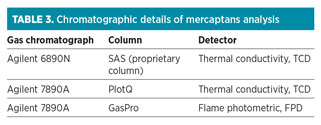
All mercaptans analysis was performed onsite. A 10-min run time was allowed after chemical injection was initiated, before sampling for each data point. Local reverse osmosis water was used for the injection and chemical formulation. The method for analyzing mercaptans was performed using a gas chromatograph and by introducing calibration samples for proper reference. A calibration curve was then constructed for every mercaptan analyzed. The results were initially obtained in ppm on a volume basis, and then further converted to ppm weight.
Table 3 presents the various chromatographic details used in the quantification of mercaptans.
 |
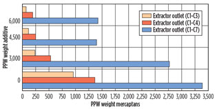
Mercaptans-removal performance. The data for the accumulated mercaptans concentration were plotted as a function of the additive injection concentration as in Fig. 6. The plots reflect the concentration at the outlet of the extractor (downstream of the water injection). The removal rates of C1–C3 and C1–C4 mercaptans were plotted separately so as to more effectively determine the efficiency of low-molecular-weight mercaptan removal.
 |
|
Fig. 6. Removal of mercaptans at the outlet of the extractor, |
The y-axis in Fig. 6 shows the removal of mercaptans as a function of chemical additive concentration in ppmw. A mole ratio of 0.5, 1 and 1.5 moles of active chemical per mole of total mercaptans was injected during sampling events, which is equivalent to 3,000 ppmw, 4,500 ppmw and 6,000 ppmw of the condensate stream.
The CA reduced the mercaptan levels in the condensate stream. The removal increases as the concentration of additive increases. Beyond a ratio of 1 mole, the benefit of additional CA is only marginal in terms of mercaptans removal. The test protocol using the miniaturized liquid treatment system indicates that a ratio of 1 mole is sufficient to lower the C1–C3 mercaptan levels to below 200 ppmw, and the C1–C4 mercaptan levels to below 250 ppm.
Mercaptan levels are lowered more effectively for C1–C4 mercaptans, as the smaller-size mercaptans react faster with the chemical additive (reaction kinetics, or by better molecular diffusion and mixing). It is, therefore, conceivable that the chemical injection concentration and injection rates can be optimized, with the objective to remove certain mercaptans at target levels.
Residual water analysis. The injected water used was from a reverse osmosis plant installed at the facility. The effluent injected water from the miniaturized liquid treating system was collected and further analyzed for common anions and cations. The analysis was performed using conventional ion chromatography (IC). Table 4 shows the results for the water analysis (for 1-mole ratio additive injection).
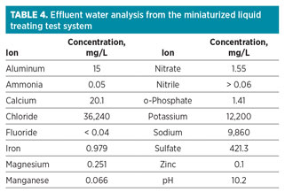 |
Analysis shows that the effluent water had increased salt contents in terms of chlorides and sodium, which are typically found in natural-formation waters (connate water). Also, the presence of calcium, magnesium, phosphate and nitrate is indicative of components present in produced water. The only two components originating from the chemical additive are sulfate and potassium. These components are generally simple to dispose of, as they are also present in natural waters. The presence of iron was interpreted as being from the naturally occurring water formation or as byproduct from pipeline corrosion.
Takeaway. A number of aspects are worth indicating as learning experiences. Operationally, it is important to mention that the chemistry performed effectively for mercaptans removal to the required levels. The results were further validated by independent onsite mercaptans testing using specialized sampling cylinders and chromatographic techniques. Additionally, other important areas to consider include:
- Interstage water wash is important for additional mercaptans-removal performance because it enhances the liquid contact surface area and provides a second reaction cycle.
- The best CA dosage is between a 0.5-mole and 1-mole ratio. The stoichiometric mole ratio is 1 mole of mercaptans per 0.5 mole of CA. A higher mole ratio removes further mercaptans only marginally.
- Temperatures above room temperature are beneficial for rapid chemical reaction rates.
- Condensate filtration upstream of the chemical injection is needed to protect the system (injection points, contactor and extractor) from suspended particulates.
- Lower-molecular-weight mercaptans are more effectively removed.
- Piston cylinders are critical for condensate/NGL sampling to maintain sample integrity if testing low-boiling-point contaminants.
Scaleup considerations. The condensate stream presented high solids content and fouled the miniaturized liquid treating system contactor/extractor more rapidly than anticipated. High solids content was observed intermittently in the wash water, possibly caused by line cleaning. This aspect should be verified in any future condensate treating application.
The full-size liquid treating process system will be a two-stage system equipped with a chemical injection (Stage 1) and water wash system (Stage 2). Depending on the design, the entire system will have an approximate footprint of 25 ft × 25 ft and a height of 7 ft.
Maintenance is not expected to be high with filter changeouts on a monthly basis. Yearly changeouts of the internals for the microfiber polymeric contactor/extractor are also expected. GP
ACKNOWLEDGMENTS
The authors would like to acknowledge Juan Carlos Ruiz and Chris Wiseman from Encana Corp. for their support. They also acknowledge Sulphur Experts personnel for their insights and Michael Quinlan from KBR for his support and guidance during the final preparation of this article.
LITERATURE CITED
1Stewart, M. and K. Arnold, Gas Sweetening and Processing Field Manual, 1st Ed., Elsevier, 2011.
2Kohl, A. L. and R. Nielsen, Gas Purification, 5th Ed., Gulf Publishing, 1997.
NOTES
aNexo Solutions’ patent-pending Exion process technology
bNexo Solutions’ Exion LT-200 chemical additive
cNexo Solutions’ Exion LT liquid treating system
 |
David Engel has more than 20 years of industrial experience in a variety of technical areas. He is the inventor in 17 US invention patents and the author of a number of technical and scientific papers. He has presented a number of seminars and technical courses on a variety of process engineering and chemistry subjects. Dr. Engel is the cofounder of Sulphur Experts—Filtration Division, a managing director of Nexo Solutions, and a technology VP at EXION Systems. He holds a BS degree in industrial chemistry and a PhD in organic chemistry. He is a member of the American Chemical Society and the Gas Processors Association, president of the American Filtration and Separation Society (Southwest Region), a GLC Consulting member, and a board member (editor) for Elsevier and Genesis BioHealth.
 |
Heath Burns is a systems specialist and engineer for Nexo Solutions in The Woodlands, Texas. He specializes in separations engineering, and has a well-rounded background in manufacturing, research and development, pilot testing, engineering design and business development. Mr. Burns has extensive field experience in solid/liquid, liquid/liquid and gas/liquid separations. He has worked intimately in the field, developing methods for evaluating filters, coalescers and separators. Mr. Burns also consults for Filtration Experts, working alongside Amine Experts, both divisions of Sulphur Experts International. He has 15 years of experience in the oil and gas industry.
 |
Scott Williams is a process engineer at Nexo Solutions. He has industry experience in many projects, and has been instrumental in providing solutions in oil and gas, petrochemical, chemical and water treatment applications. As part of the engineering group, Mr. Williams is responsible for technical design and solutions development in engineering and technology applications, and he also provides support for Nexo’s analytical and specialized service projects. He holds a BS degree in chemical and biological engineering from the University of Colorado at Boulder.


Comments