
Carbon dioxide-tolerant nitrogen rejection reduces costs
A. Farooq, A. Finn, A. Hosainy and G. Johnson, Costain Natural Resources, Manchester, UK
For commercial-scale nitrogen (N2) removal, cryogenic distillation is the only cost-effective technology. Cryogenic N2 rejection produces a high-purity N2 waste stream, which can be vented to the atmosphere and which achieves very high hydrocarbon recovery with low power consumption.
Cryogenic N2-rejection processes that employ a pre-separation distillation unit can handle up to 60 times as much feed gas CO2 as processes that do not use pre-separation. A new process, achieved through the modification of an established cryogenic N2-rejection process, allows up to approximately 2 mol% CO2 content in the feed gas to the cryogenic N2-separation process. This allowance reduces capital and operating costs by eliminating or reducing the upstream removal of CO2. It also eliminates the risks associated with the handling and storage of chemicals typically required for CO2 removal.
N2 is inert and does not burn, so natural gas containing excessive N2 (typically more than 4 mol%–5 mol%) must be processed to remove N2 to meet sales gas minimum heating value specifications. Gas fields with high N2 levels exist in Siberia, Eastern Europe, the Midwest US, The Netherlands, the Irish Sea, the North Sea, Pakistan and Southeast Asia. In all of these locations, N2 removal (rejection) is potentially important.1
N2 removal also reduces gas transportation costs. If natural gas is to be used as petrochemical plant feedstock, then the N2 content must be even lower—potentially less than 1 mol%. The lower N2 content is necessary because N2 is very difficult to separate from carbon monoxide (CO) in synthesis gas formed by steam methane reforming. If not removed, N2 can cause serious bottlenecks in petrochemical production.
N2-removal technologies. The technologies available for N2 removal from natural gas include pressure swing adsorption (PSA) and rubbery membranes. However, for commercial-scale N2 removal (at flowrates greater than 20 MMscfd), cryogenic distillation is the only cost-effective technology.1, 2 Rubbery membranes are limited to much lower flowrates and are only economical for fuel gas conditioning. A crucial advantage of cryogenic N2 rejection is that it produces a high-purity N2 waste stream, which can be safely vented to atmosphere.
Cryogenic processing also achieves greater than 99% hydrocarbon recovery, to maximize revenue. It has relatively low power consumption and small sales gas compressor(s). Alternative process technologies produce methane (CH4)-rich N2 waste streams that present disposal challenges and bigger compression requirements.
Cryogenic N2 rejection units (NRUs) operate at temperatures as low as –190°C and require upstream removal of feed gas components that could freeze and cause equipment blockage. Water is easily removed by molecular sieves, and heavier hydrocarbons are removed by partial condensation or proven dewpointing techniques, such as silica gel adsorption.
CO2 must also be considered, to prevent it from freezing. The CO2 content of natural gas varies widely, but CO2 is commonly present at levels up to several percent and above. These levels are too high for an NRU, as CO2 solidifies at NRU operating temperatures. The amount of CO2 tolerable in the NRU feed is limited by its solubility in methane at the low NRU temperatures.3 Therefore, CO2 removal is typically required upstream of the NRU.
Depending on the NRU process configuration, the practical CO2 limit in the feed gas may be as low as 50 ppmv, akin to that of an LNG plant. However, this is only true for very high-N2-content gas, so considering CO2 removal requirements in the same way as for LNG is erroneous. This is because, when the feed gas N2 content is less than 30 mol%, a preseparation column is commonly used to remove methane at elevated pressure (and temperature). This significantly reduces power consumption, compressor size, capital cost and overall processing cost. The rectification section of the preseparation column removes CO2 from the overheads, so much less CO2 enters the colder downstream section of the NRU, and the plant feed gas can potentially contain up to 0.3 mol% CO2 without creating any freezing concerns.
An NRU design can be made more CO2-tolerant (up to the 0.3 mol% figure), and this can be beneficial to acid gas removal cost and/or provide a “buffer” to plant upsets. However, the issue remains that, while N2 removal by cryogenic processing is clearly optimal, a cost burden normally exists for CO2 removal. PSA technology can remove CO2 as well as N2, but, as noted previously, this potential advantage is outweighed by excessive compression costs at flowrates over 20 MMscfd. Therefore, efficient removal of N2 from natural gas almost inevitably requires adjunct CO2 removal, even though the sales gas CO2 specification may be already met.
Several well-established processes for CO2 removal exist, but all incur significant cost and may impact NRU reliability and operation. Therefore, an incentive exists to avoid CO2 removal upstream of cryogenic NRUs by making the NRU design more tolerant to CO2.
Conventional cryogenic NRU process. If the feed gas N2 content is higher than around 30 mol%, as is typically found in Eastern Europe, then the N2 removal is conventionally carried out in a cryogenic double-column process for excellent process integration, high thermodynamic efficiency and minimal power consumption for methane compression.4 The feed gas is subjected to very low temperatures, which limit the feed gas CO2 concentration to 50 ppmv–100 ppmv; otherwise, freezing would occur.
Natural gas that requires N2 removal normally has a much lower N2 level than 30 mol%. In these applications, a preseparation distillation column is commonly used.5, 6 These columns operate at relatively high pressure and temperature, approximately 30 bar–35 bar and –115°C as the coldest temperature.
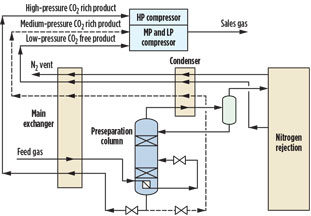
As its name suggests, the preseparation distillation column removes a portion of the feed gas CH4 before the downstream N2-CH4 separation (to produce low-CH4-content N2). The downstream separation processes only a fraction of the feed gas, which greatly improves process efficiency and reduces power consumption and cost. The methane from the preseparation column is at relatively high pressure, so compression to sales gas pressure consumes less power (and makes the overall sales gas compression system simpler, in most cases). Fig. 1 shows a typical NRU flowsheet incorporating a preseparation column.
 |
|
Fig. 1. Typical NRU with preseparation column. |
NRUs are autothermal and do not require external refrigeration, as the required refrigeration is provided by one or more evaporating methane streams. Optimizing the overall separation system, the provision of refrigeration and the sales gas compressor system together greatly increases thermodynamic efficiency and reduces compression costs. Therefore, the processing costs of N2 rejection have fallen significantly in recent years.
In Fig. 1, the feed gas is partially condensed by returning product streams, and it enters the preseparation column. This column has an overhead condenser to provide reflux to limit methane going downstream. It also limits the CO2 content in the gas flowing to the colder downstream distillation.
The bottom product from the preseparation column contains typically 1 mol%–4 mol% N2 and essentially all of the CO2 in the feed gas, due to CO2 being less volatile than methane. Evaporation of this stream provides refrigeration for condensing the feed gas and preseparation column reflux. The product from the downstream N2-rejection column system is evaporated at lower pressure, and it provides refrigeration in the colder section of the plant. Once evaporated, the bottom products from both the preseparation and N2-rejection section can be combined and compressed to sales gas pressure.
Since the preseparation column overhead reflux removes most of the CO2 from the feed stream in the preseparation column bottoms (at relatively high pressure and temperature), increased feed gas CO2 content to the NRU can be tolerated—up to around 0.3 mol%—when compared to a process without preseparation. The feed gas CO2 limit is influenced by the N2 content of the feed gas and the amount of methane removed by the preseparation column.
The limitation of 0.3 mol% is in place because the bottom stream from the preseparation column (dashed stream in Fig. 1) is let down in pressure to condense the feed gas and preseparation column overheads. If the CO2 content in the feed gas were higher than approximately 0.3 mol%, then CO2 would solidify on pressure let-down due to the temperature reduction from the Joule-Thomson effect. Therefore, if this pressure let-down could be avoided, then a higher CO2 level—of up to 2 mol% CO2—would be feasible; i.e., within solubility limits.
This increase in CO2 tolerance could actually avoid the need for upstream CO2 removal and provide significant cost savings. An alternative source of refrigeration would be required; however, if it can be provided relatively easily, using established principles and process equipment, then significant cost savings are feasible without increased technical risk.
CO2-tolerant process. A modified NRU process has been developed that avoids the need for pressure let-down of the bottoms stream from the preseparation column by using an alternative source of refrigeration. A CO2-free methane stream is sourced from downstream of the preseparation column and employed in a refrigeration cycle.7
Similar to the NRU process described above, the low-CO2-content bottoms product from downstream distillation is evaporated to provide refrigeration. However, instead of combining it with the preseparation column bottoms to flow to compression, the low-CO2-content stream is compressed in a separate stage in the compressor system.
A part of the low-CO2-content stream from downstream of compression is then recycled, condensed, let down in pressure and evaporated at one or more pressure levels to provide refrigeration to condense feed gas and for the preseparation column condenser (see dashed line in Fig. 2). The evaporated stream is then returned to the compressor system. Although two different compressor systems are required, they may actually share a common driver to reduce costs.
 |
|
Fig. 2. CO2-tolerant NRU. |
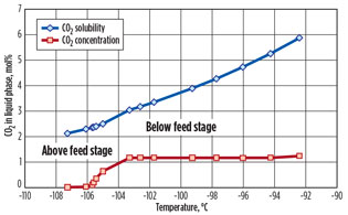
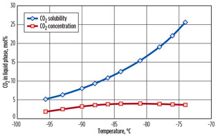
A case study is presented for a natural gas stream containing 20 mol% N2 and 1 mol% CO2.7 A feed gas flow of 200 MMscfd at 45 bar and 45°C is assumed. Key process parameters are outlined in Fig. 2. The predicted CO2 solubility is presented for the key process streams, where CO2 freezing could potentially occur, in Fig. 3 (preseparation column, stage by stage) and in Fig. 4 (evaporating preseparation column bottoms stream).
 |
|
Fig. 3. CO2 concentration vs. predicted solubility limit for |
As can be seen in Figs. 3 and 4, ample operating margin exists between the predicted CO2 concentration and the solubility limits, so no CO2 freezing would occur for a feed with a CO2 content of 1 mol%. Fig. 4 shows the predicted solubility and CO2 concentration of the bottom product from the preseparation column. As discussed, let-down in pressure of this stream is the limiting factor for CO2 freezing and, as such, limits the amount of CO2 that can be present in the feed gas. The new process avoids such low pressure, and so the amount of CO2 in the feed can be greater.
 |
|
Fig. 4. CO2 concentration vs. predicted solubility limit in |
Fig. 4 also shows a predicted limit of around 5 mol% CO2 in the bottom product from the preseparation column. Therefore, the CO2 content in the feed stream can be higher than shown in the case study (up to approximately 2 mol%) before freezing is predicted. Accurate prediction of CO2 solubility is ensured by using a fully rigorous solid-vapor-liquid fugacity methodology that has been benchmarked against leading CO2 freezing prediction models.8
The net power consumption of the new process is the same as the conventional process for a feed gas containing 0.3 mol% CO2. This is because the new process allows the CO2-rich product stream from the preseparation column to be evaporated at elevated pressure, which reduces compression power and offsets the refrigeration cycle compression power. Also, the refrigerant stream is nearly pure methane, whereas the preseparation column bottom product can contain significant C2+ content, affecting evaporating temperature and requiring lower evaporating pressure.
The key benefit of the new process is that, for natural gas streams containing less than 2 mol% CO2, an upstream acid gas removal unit (AGRU) can be avoided. Eliminating CO2 removal can result in significant cost savings, increased plant reliability, improved operability, reduced operator and maintenance burden, and improved safety, as there is no need to store and handle CO2-removal chemicals. Not only is the AGRU cost avoided, but, since feed gas is normally warmed in an AGRU, the dehydration unit is smaller, resulting in additional capital cost savings. The new process introduces no additional risks to operability or performance.
With regard to capital costs, the estimated split of capital costs for an NRU system (based on gas turbine drive) is typically:
- AGRU: 20%
- Dehydration: 13%
- NRU: 22%
- Compression: 45%.
If the new process avoids the need for an AGRU, then, given the other savings on dehydration and allowing for the additional compression for the refrigeration loop, the typical overall capital cost reduction will be approximately 10%–15%. Additional savings on utility heat, operating and maintenance costs could reduce processing costs by 15%–20%.
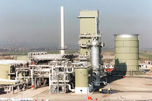
Established cryogenic NRU technology. Cryogenic NRU technology has been successfully implemented in major gas processing facilities, characterized by optimized distillation designs and energy integration by using multi-stream aluminium plate-fin heat exchangers. These plants are said to exhibit high energy efficiency, low compression power, very low hydrocarbon losses and excellent turndown characteristics. They provide a high rate of return and low processing costs, with minimal environmental impact. The new process is based on these well-proven, high-performing and reliable NRUs.
 |
|
Fig. 5. Connah’s Quay Gas treatment plant, with |
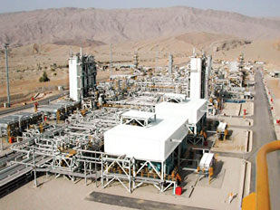
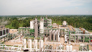
The Connah’s Quay gas treatment plant (E.ON) in Wales, UK handles up to 200 MMscfd of natural gas containing 10 mol% N2 and 0.3 mol% CO2 (Fig. 5).9 A similar facility, for Eni Pakistan’s gas concession in the Bhit Mountains, treats 270 MMscfd of gas with 18 mol% N2 content in two trains (Fig. 6).10
 |
|
Fig. 6. Eni Pakistan gas processing facility. |
The NRU supplied to PEMEX in Villahermosa, Mexico has two trains, each with a capacity of 300 MMscfd. The plant is designed to operate with increasing feed gas N2 over time as N2 breaks through in the associated gas (Fig. 7) from enhanced oil recovery.
 |
|
Fig. 7. Cuidad PEMEX gas plant in Tabasco, Mexico. |
All of these NRUs are proven in meeting product specifications reliably, safely and efficiently.11 In all cases, the NRU facilities were optimized to give a conventional, efficient and reliable sales gas compression configuration.
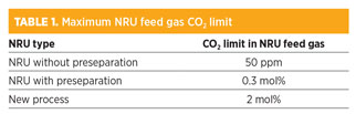
Takeaway. Table 1 summarizes the approximate maximum allowable CO2 in NRU feed gas for an NRU without preseparation, with preseparation and with the new process.
 |
The new process introduces a relatively small modification by using an alternative source of refrigeration. This improves the CO2 tolerance of a well-proven cryogenic NRU with no loss in operability, flexibility or hydrocarbon recovery, and with no increase in overall power consumption.
The new process can eliminate an upstream AGRU, which results in the following key benefits:
- Significant capital and operating cost savings
- Increased plant reliability and operability
- Reduction in operator and maintenance burden
- Avoid warming of feed gas by AGRU, resulting in smaller dehydration unit and less NRU heat exchange area.
The new CO2-tolerant process allows CO2 concentrations of up to approximately 2 mol% in the feed gas—a significant increase compared to the conventional approach. GP
ACKNOWLEDGMENTS
The authors would like to thank Terry Tomlinson for his assistance in preparing this paper.
LITERATURE CITED
1Finn, A. J., “Rejection strategies,” Hydrocarbon Engineering, October 2007.
2Johnson, G. L. and T. Eastwood, “Nitrogen rejection from natural gas,” GPA Europe Spring Conference, Copenhagen, Denmark, May 27, 2011.
3“Section 16: Hydrocarbon recovery,” GPSA Engineering Data Book, 13th Ed., 2012.
4Cholast, K. and A. Kociemba, “Technology assessment for two-phase LNG expanders operating for ten years in gas liquefaction process,” 30th GPAE Annual Conference, Edinburgh, Scotland, September 18–20, 2013.
5Trautmann, S. R. and K. H. Janzen, “Innovative NRU design at Pioneer Natural Resources’ Fain gas plant,” 79th GPA Annual Convention, Atlanta, Georgia, March 13–15, 2000.
6O’Brien, J. V. and J. J. Maloney, “Continuous improvement in nitrogen rejection unit design,” Hydrocarbon Engineering, September 1997.
7Johnson, G. L. and A. J. Finn, “Process and apparatus for separation of hydrocarbons and nitrogen,” International Patent No. WO 2014/167283 A2, 2014.
8Eggeman, T. and S. Chafin, “Beware the pitfalls of CO2 freezing prediction,” Chemical Engineering Progress, March 2005.
9Healy, M. J., A. J. Finn and L. Halford, “UK nitrogen removal plant starts up,” Oil & Gas Journal, February 1999.
10Millward, R. J., A. J. Finn and A. J. Kennett, “Pakistan nitrogen removal plant increases gas quality,” GPA Europe Annual Conference, Warsaw, Poland, September 21–23, 2005.
11Wilkinson, D. and G. L. Johnson, “An Abu Dhabi case study,” Hydrocarbon Engineering, February 2012.
 |
Adil Farooq is a process engineer at Costain in Manchester, UK, with responsibility for hydrocarbon processing projects, including conceptual design, Pre-FEED, FEED and detailed design. His three years with Costain have been spent on cryogenic gas processing projects. He has a bachelor’s degree in chemical engineering and a master’s degree in advanced chemical engineering, both from the University of Manchester, UK. Mr. Farooq is an associate member of the IChemE in the UK.
 |
Adrian Finn is process technology manager at Costain in Manchester, UK, with responsibility for process technology development and commercialization, proposal management and supervision of feasibility studies, pre-FEEDs and FEEDs. He has spent 32 years with Costain, mainly on cryogenic gas processing projects. He has authored nearly 50 technical papers and holds nearly 20 granted patents in gas processing. He earned a bachelor’s degree in chemical engineering and fuel technology from Sheffield University, UK and a master’s degree from the University of Leeds, UK. Mr. Finn is a fellow of the Institution of Chemical Engineers (IChemE), a chartered engineer in the UK, a member of both the management and program committees of GPA Europe.
 |
Ahmad Hosainy is a graduate process engineer at Costain in Manchester, UK. He has worked on various technical studies, pre-FEEDs and detailed design in hydrocarbon processing involving a range of gas processing technologies. Mr. Hosainy holds an MEng degree from the University of Manchester, UK. He is also an associate member of the IChemE.
 |
Grant Johnson is front end solutions manager, responsible for activities in oil and gas, at Costain in Manchester, UK. He joined Costain in 1997, with a master’s degree in chemical engineering from the University of Cambridge, UK, and has since worked on a number of large gas processing facilities. He holds patents in the field of natural gas processing, covering nitrogen removal, liquefaction and liquids recovery. Mr. Johnson is a member of the IChemE, a chartered engineer in the UK.


Comments