
Minimize evaporation losses by calculating boiloff gas in LPG storage tanks
S. Shiva Shamekhi and N. Ashouri, Faradast Energy Falat Co., Tehran, Iran
Liquefied petroleum gas (LPG) is stored and transported in tanks as a cryogenic liquid, at a temperature below its boiling point near atmospheric pressure. Due to heat entering the cryogenic tank during storage and transportation, a portion of the LPG continuously evaporates, creating a gas called boiloff gas (BOG). BOG causes evaporation losses in the LPG supply chain over time.
It is imperative to minimize vaporization and displacement losses due to the economic and safety problems that can result from such losses. The amount of BOG depends on the design and operating conditions of LPG plants. In the LPG supply chain, BOG can be reliquefied or sent to the flare and burned. The evaluation of BOG in a storage tank in all operating scenarios is important for the correct selection and design of a BOG compressor.
Different sources exist for the generation of BOG. These sources include heat leaks from ambient air around the storage tank, heat ingress due to the dissipation of pumping power inside the tanks, heat leaks from pipelines, flash vapor generated by liquid rundown and displaced vapor from the tank due to liquid filling (known as the piston effect).
In this study, boundary conditions and parameters have been implemented to accurately estimate the amount of BOG that evaporates at the C3 and C4 refrigeration and loading facilities at the Bandar Abbas gas condensate refinery in Iran.
Study outline. The produced propane and butane from propane/butane splitter units are cooled down in the propane/butane refrigeration unit via open-cycle refrigeration, and then run down to the associated refrigerated tanks and stored at atmospheric pressure before being exported to overseas markets via propane/butane carrier ships.
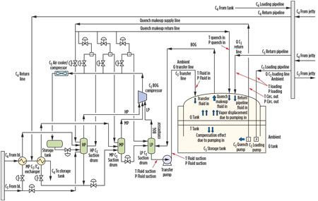
As shown in Fig. 1, butane rundown is subcooled at the required temperature level in two exchangers in series, both utilizing propane. The chilled butane is then sent to the storage tanks.
 |
|
Fig. 1. Propane refrigeration BOG production. |
Propane is divided into two streams. One stream flows to the first exchanger and is flashed, and the other stream is sent to the high-pressure C3 suction drums and then flashed in the second exchanger. Liquid propane from the suction drum is utilized in the second exchanger, and relevant flashed vapor is sent to medium-pressure C3 suction drums and then to the low-pressure C3 suction drums.
Liquid propane flashes to lower pressure levels in medium- and low-pressure suction drums before being pumped to refrigerated storage tanks. Propane vapors result from the rundown product pressure reduction, and flashes at the different pressure levels are compressed in two parallel, three-stage centrifugal compressors, before being condensed in a C3 air cooler and a C3 compressor condenser. Liquid propane is collected in a C3 accumulator and flashed again to the high-pressure suction drum to restart the cycle.
Boiloff vapors from propane tanks are sent to the low-pressure suction drums and then to the first compressor stage. No vapors develop from butane tanks due to the subcooling of the stored liquid product.
Two tanks each are used for C3 and C4 storage. Since the boiloff calculation method can be used for both types of storage tanks, calculations are described for only one of the C3 storage tanks.
Operating modes. To load propane and butane to the ship, it is necessary to cool down the pipelines at the lowest possible temperature, with the aim of reducing BOG production during the entrance to the ship compartments. Three steps are needed: preloading, loading and holding. Pre-loading includes two parts—the initial phase and the final phase—to achieve cooling of the pipeline with low flowrates and appropriate pipeline temperature, respectively.
As a general rule, each tank follows three steps during normal operation:
- Filling mode: The tank receives the product from the process unit at rundown flowrates. During the filling mode, it is necessary to prepare the tank for ship loading; in project documentation, this operation is called preloading.
- Emptying mode: When the ship is ready to receive the products (i.e., when the pipeline is at proper temperature, parcels are at proper temperature, loading arms are connected, etc.), then it is possible to transfer the product from tank to ship. This operation is called loading.1
- Holding mode: The tank is full of product and ready for ship loading, but the ship has not yet arrived or is not ready for loading. This operation is called holding.
To load propane to the ship, it is necessary to cool down the two pipelines at the lowest possible temperature, with the aim of reducing BOG production when products enter the ship compartments. Therefore, some days before the carrier ship arrives, circulation from the storage tank to the jetty and back to the tank is started. This process is applied when the pipelines are in equilibrium with the external temperature.
The preloading mode is the most critical operating mode from the point of view of BOG production, due to the great quantity of hot fluid trapped in the pipeline. For this reason, it is necessary to avoid a too-rapid displacement of the fluid to prevent abnormal overdesign of the BOG compressor.
One of the major sources of boiloff production in liquefied gas handling is rollover, which can result in a boiloff rate several times greater than normal, causing rapid over pressurization while venting a considerable quantity of vapors to atmosphere. When the liquid layer adjacent to a liquid surface becomes denser than the layers beneath due to boiloff of lighter fractions from the tank, stratification develops and causes rollover due to rapid mixing as a result of density inversion. An effective solution is the mixing of the liquid in the tanks. For this purpose, two circulating pumps are placed inside the tank: one is always circulating the liquid and the other is used for cooling the transfer line.
Calculation methods. BOG evaluation in all operating scenarios of the tank is important for the correct definition of the flowrates to the BOG compressors.
BOG is produced under the following conditions:
- Heat absorbed from ambient air by refrigerated storage tanks
- Heat absorbed from ambient air by lines (rundown lines, pipelines)
- Heat produced by the operation of pumps (loading, circulation, rundown)
- Vapor displacement due to liquid inlet in the tank
- Rapid variation of barometric pressure.
Total BOG flowrate can be calculated with Eq. 1:
BOGTotal = BOGTank + BOGTransferLine + BOGLoadingSystem +
BOGElectricalMotor + BOGATM + BOGCirculationSystem + (1)
BOGVaporDisplacement + BOGCompensationEffect
Note: The contribution of BOG due to rapid atmospheric pressure variation is not considered, and is negligible when compared to the other contributions. Also, the compensation effect due to outflow of liquid from the tank is not considered.
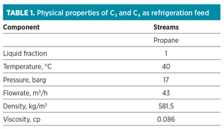
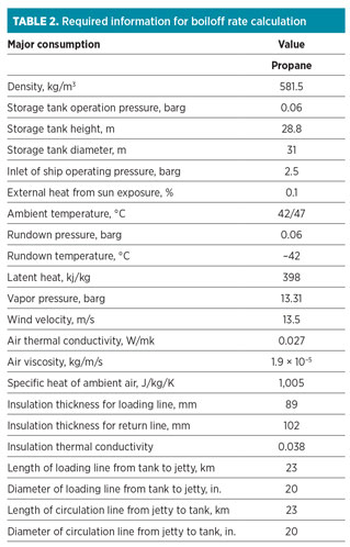
BOG is calculated utilizing simulation software. The thermophysical properties of propane are collected in Table 1. Required information for the calculation of BOG is presented in Table 2. Calculations for the contribution to BOG by heat absorbed in tanks are shown in Eqs. 2 and 3.
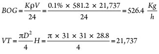 (2), (3)
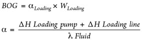
Heat ingress by storage tank is equal in the three cases of holding, preloading and loading. Equations for the contribution to BOG by the transfer system are shown in Eqs. 4–9.
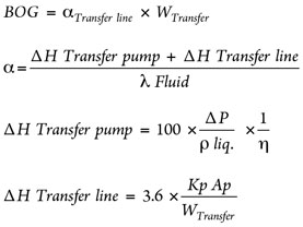 (4), (5), (6), (7)
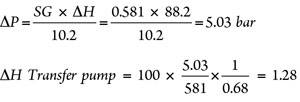 (8), (9)
where:
QNormal=21.3 m3/h
QMax=67.5 m3/h
Head=88.2 m
η=0.68 (ηShaft 0.75 × ηMotor 0.9)
ΔP=SG × ΔH
The ΔH transfer line is calculated by HYSYS.
BOG pertaining to lines (circulation, loading and transfer line) can be calculated manually using Eqs. 10–14.2
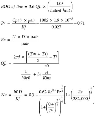 (10), (11), (12), (13), (14)
Calculations for the contribution to BOG by the circulation system are shown in Eqs. 15–20.
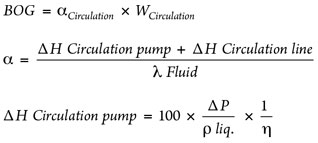 (15), (16), (17)
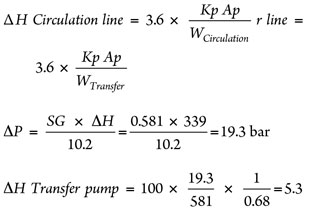 (18), (19), (20)
where:
QNormal=225 m3/h
Head=339 m
η=0.63 (ηShaft 0.7 × ηMotor 0.9)
Calculations for the contribution to BOG by the loading system are shown in Eqs. 21–26.
 (21), (22)
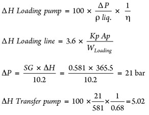 (23), (24), (25), (26)
where:
QLoading=1,250 m3/h
Head=365.5 m
η=0.72 (ηShaft 0.8 × ηMotor 0.9)
Calculations for the contribution to BOG by electric motors are shown in Eqs. 27–28.
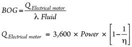 (27), (28)
where:
Power of loading pump = 904.3 kw
Power of circulation pump = 172.7 kw.
The calculation for the contribution to BOG by vapor displacement is shown in Eq. 29.
![]() (29)
(29)
Rundown flowrate definitions include:
- The normal flowrate is 21.3 m3/h on the transfer pump when the system is in holding mode
- The maximum pump flowrate is 67.5 m3/h for the transfer pump when the system is in preloading mode (initial phase)
- ρ is determined by the simulator and is derived from flashing before entrance to the storage tanks.
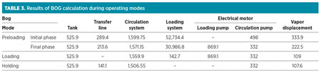
The results for the different operating modes experienced by storage tanks are shown in Table 3.
Takeaway. The calculations described represent a simple approach for engineers to estimate produced BOG ratio in cryogenic systems for LPG and LNG. The BOG ratio can be calculated manually or with the use of a process simulator. GP
ACKNOWLEDGMENT
The author thanks the board of directors and the process division of Faradast Energy Falat Co., the general contractor of Bandar Abbas Gas condensation refinery, for its support.
NOMENCLATURE
λ Latent heat
α Vapor fraction
η Pump shaft efficiency
W Mass flow
Kp Average heat flux through the pipe, W/m2
Ap Piping external surface area, including insulation, m2
H Enthalpy
Kt Vaporization coefficient, considered equal to 0.001 for C3/C4
Vt Geometrical volume of tank, m3
ρ Density
Kf Thermal conductivity of ambient air, W/km
Kins Thermal conductivity of insulation, W/km
LITERATURE CITED
1Chen, C. C., “Fine-tune refrigerated LPG loading line operation,” Hydrocarbon Processing, August 2005.
2Wordu, A. A. and B. Peterside, “Estimation of boiloff gas from refrigerated vessels in liquefied natural gas plant,” International Journal of Engineering and Technology, Vol. 3, No. 1, January 2013.
3Adom, E., et al. “Modelling of boiloff gas in LNG tanks: A case study,” International Journal of Engineering and Technology, Vol. 2, No. 4, 2010, pp. 292–296.
 |
S. Shiva Shamekhi is a process engineer in the process engineering department of Faradast Energy Falat Co. She is working on a mega-size project for a gas condensation refinery in Tehran, Iran. She holds BSc and MSc degrees from Amirkabir University of Technology in Iran. Her areas of specialization include basic design of refrigeration plants and detailed design of gas and petrochemical plants. She can be reached at S.Shamekhi@fefalat.com or s.shamekhi@gmail.com.
 |
N. Ashouri is the process lead engineer in the process engineering department of Faradast Energy Falat Co. He is working on a mega-size project for the Bandar Abbas gas condensate refinery in Iran. He has 16 years of experience in the design of oil and gas refineries. Mr. Ashouri holds an MSC degree in process engineering from the Iran University of Technology. He can be reached at N.Ashouri@fefalat.com.


Comments