
Efficiently design and operate vertical gas/liquid separators
P. Diwakar and J. Valappil, Bechtel Oil, Gas and Chemicals Inc., Houston, Texas
Gas/liquid separators, or knockout drums, are used to eliminate liquid droplets from incoming multiphase flows and prevent liquid carryover to downstream compressors and rotating equipment. Liquid in any quantity is a safety concern, since droplets may cause erosion damage in blades and corrosion in other downstream equipment, especially in the presence of water.
The mechanisms governing the separation of liquids and solids from gas include gravity, inertia, shear and turbulence. Most separators use a combination of these mechanisms. The most important principles in a liquid-gas separator are to ensure that:
- Smaller droplets are not formed due to droplet shearing or impingement, which would make it more difficult for a mist-eliminator device to coalesce and separate it from the gas
- The velocity of the gas carrying the droplets and particulates is low enough as it approaches the mist-eliminator device, as governed by the K factor
- The superficial velocity is uniform over the entire area of the mist-eliminator device, with the peak velocity not more than 10% above the mean velocity.
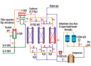
The importance of the removal of liquids, particulates and heavies is emphasized by the number of separation stages required before the feed gas reaches a compressor in the process diagram shown in Fig. 1.
 |
|
Fig. 1. Process schematic showing several liquid separation |
The dryer inlet filter separator may take a higher liquid load and separate liquids of the order of 10 µ and higher. A filter coalescer as the next stage is capable of separating droplets in the submicron range. Dehydrators made of beds of semi-permeable absorbent can remove almost all liquid hydrocarbons or water.
The sizing of each of the components of a knockout drum is not trivial, and advanced simulation tools must be used to ensure that the device operates as designed. In this article, design guidelines for different separator sections—starting with the upstream piping—are discussed. Validation and post-processing figures come from computational fluid dynamics (CFD) combined with 1D calculations and empirical correlations.
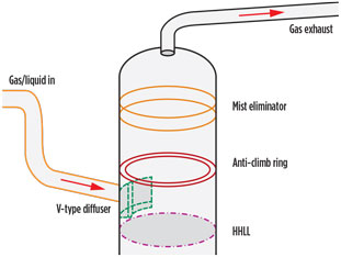
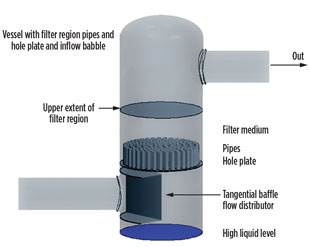
Inlet and upstream piping requirements. Figs. 2 and 3 show examples of liquid/gas separators. The multiphase flow, which consists of gas and liquid, such as water and hydrocarbon from upstream, enters the vessel through the inlet nozzle. The upstream flow regime is typically governed by the incoming mass flowrate; piping configuration such as bends, elbows, vertical or horizontal pipe; mass or volume fraction of liquid or solid in gas; and inlet momentum.
 |
|
Fig. 2. Dryer inlet separator and filter coalescers. |
|
|
|
Fig. 3. Vertical and horizontal filter coalescers. |
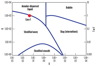
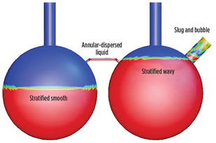
Taitel-Dukler flow maps for horizontal piping, and Hewitt and Roberts flow for vertical pipes, may be used to determine the flow regime of the incoming flow. Inlet piping should be sized so that the multiphase flow is in the stratified wavy regime to minimize the amount of dispersed liquid in the gas flow, and to separate the bulk of the liquid entering the knockout drum. The mist fraction of liquid increases while the maximum droplet size decreases. The increase can be quite substantial if the flow regime moves into the annular-dispersed phase.
The sizing requirements are governed by the kinetic energy, or the inlet momentum. The higher the energy of the gas flow, the higher the velocity and the higher the tendency for larger droplets to be carried against gravity toward the demisting device. For vane-type inlet devices, approximately 6,000 kg/ms2 are allowed, since the velocities are lowered and distributed as the flow passes through the vanes. For other inlet devices that may induce shear and shatter droplets, the momentum should be approximately 1,500 kg/ms2.
|
|
|
Fig. 4. Taitel and Dukler maps for two-phase flow |
Bends and elbows in the upstream piping play a significant role in droplet shattering due to the impingement creating smaller droplets that are more difficult to separate, since they are easily carried by the gas stream. Further centrifugal forces (due to flow turning at right angles) and swirl (due to rotational momentum) may force liquid to one side of the vessel, placing an uneven distribution of liquid into the vessel and going up to the demisting device.
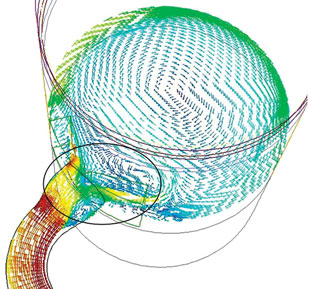
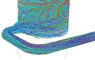
These forces can produce localized flooding, which leads to larger liquid carryover at the outlet of the knockout drums. The maldistribution in the flow field into the vessel is shown in Figs. 5 and 6. This situation may also lead to more liquid stripped from the liquid-free surface if liquid is present in the vessel. A diameter of at least 10 in. to 15 in. of straight piping upstream is recommended for the flow to fully develop on approaching the vessel. Anti-swirl devices and turning vanes may be placed upstream to even out the flow entering the vessel.
|
|
|
Fig. 5. Uneven incoming flow due to bends. |
|
|
|
Fig. 6. Swirling flow due to elbows in upstream piping. |
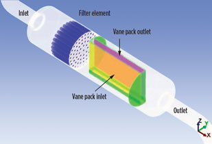
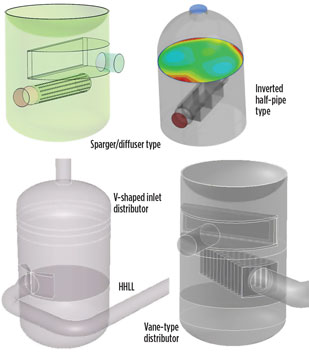
Inlet diffuser device selection. Inlet devices are equally important in determining the amount of liquid and droplet size carried to the demisting device. Some of the most common types of inlet devices are shown in Fig. 7. The main function of the inlet device is to improve the separation of bulk liquid from the gas and decrease the load on the demister. A properly sized inlet device should reduce the feed gas momentum and ensure a uniform distribution at the mist eliminator entry, as well as eliminate local overloading or flooding.
|
|
|
Fig. 7. Common types of inlet devices. |
Inlet conditions are determined according to properties of the incoming media:
- Physical properties of gas, such as density and viscosity, determined by operating pressure and gas composition
- Liquid-phase properties, including viscosity, density and surface tension
- Droplet-size distribution of the liquid phase
- Gas-to-liquid ratio.
The requirements of the separation operation are determined according to:
- The separation efficiency related to mist, slug, solid, etc.
- Turndown ratio
- Allowable pressure drop
- Sizing constraints.
Other than these slotted T-type distributors, tangential inlet, cyclone type, dual vanes and multi-vanes are used. In general, the inverted half-pipe, sparger or V-shaped distributors are not recommended, mainly due to liquid re-entrainment concerns.
Waves formed due to gas impingement on the free surface may lead to smaller droplet formation, and these droplets may be stripped from the waves and carried toward the mist eliminator. Flooding is a condition where the mist eliminator is choked with liquid and leads to higher-pressure droplets and large carryover of liquid at the outlet.
The Hinze1 criteria is used to determine the maximum stable droplet size and whether shearing at the inlet device will produce small droplets that will pose more challenge to
demisting operations, as shown in Eq. 1:
![]() (1)
(1)
where:
ρc=Gas density (continuous phase)
σ=Surface tension between liquid and gas
ε=Turbulent dissipation rate obtained from a CFD calculation using standard turbulence models, as shown in Fig. 8.
|
|
|
Fig. 8. Turbulent dissipation rate obtained from a CFD calculation using standard |
The calculation of a relatively larger droplet size will show that shearing of droplets at the inlet device is not at a level to create smaller droplets that will impart an extra load on the demisting device.
The smallest droplets or bubbles that can be created by dynamic forces in a shear flow are equally important to determine the level of liquid entrainment into the separator. The Weber number criteria by Kouba2 may be used for this purpose. These criteria are derived through a force balance equating capillary pressure in the droplet to the dynamic pressure, as shown in Eq. 2:
![]() (2)
(2)
where:
Vc=Velocity of continuous phase
g=Gravitational constant.
Most systems are designed and tested for water/air systems. For liquid hydrocarbon with much lower density, viscosity and surface tension, appropriate derating must be done, and the smallest droplet size calculated may be 7 to 10 times smaller than water. Therefore, hydrocarbon will govern the design of both inlet diameters and all internals in the vessel.
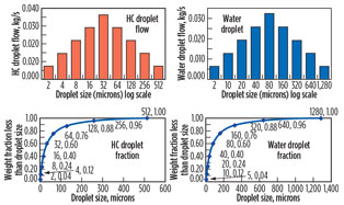
To obtain an accurate estimate of the liquid loading at the entry of a demisting device, multiphase CFD calculations are performed. A less time-consuming steady-state approach is to use a Lagrangian-Eulerian model, using droplets as discrete-phase massless particles in the gas phase dispersed in a log-normal distribution, using largest and smallest droplet sizes calculated from Eqs. 1 and 2. This is Gaussian distribution of the Log(n). A Rosin-Rammler distribution may be used only if there are solid particles for solid-gas or solid-liquid separation equipment.
Fig. 9 shows the difference between hydrocarbon and water droplet size distributions. The demisting device must be appropriately sized to take the entire load of liquid coming into the vessel. The sizing must be conservative and help minimize liquid carryover to the outlet of the vessel.
|
|
|
Fig. 9. Differences between hydrocarbon and water droplet |
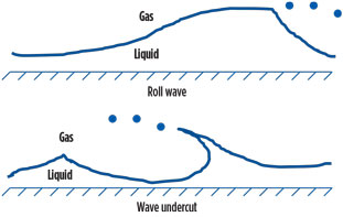
Criteria for droplet shear at free surface and re-entrainment. High-velocity gas over the surface of a liquid creates waves. Liquid droplets are sheared from the free surface and carried away by the gas stream. Most of the droplets are likely to end up at the mist eliminator unless the droplets are heavy enough to drop back down into the gravity section of the knockout drum. A schematic of a gas shear is shown in Fig. 10.
|
|
|
Fig. 10. Droplet shearing from liquid-free surface. |
The Kelvin-Helmholtz (KH) criteria can be used to calculate the sensitivity of the liquid-free surface and gas shear based on the surface tension and densities of the two media. For elevated gas speeds over liquid pools, if the flow is turbulent and the film Reynolds number exceeds 10,000, then re-entrainment will take place if gas velocity exceeds the following criteria by three to four times (Eq. 3):
![]() (3)
(3)
where:
ρ1=Liquid density
σ=Surface tension
g=Gravitational constant
ρg=Gas density
Vc=Critical gas velocity for the onset of KH waves.
If liquid droplets are formed at the tips of the waves, then the minimum size of the droplets (dmin) can be calculated using Eq. 4:
![]() (4)
(4)
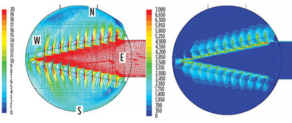
Fig. 11 compares typical gas velocities produced at the free surface for a vane-type inlet distributor and a sparger. An inlet distributor that reduces and distributes flow, and that also reduces KH waves, should be selected. A height of at least 300 mm from a high-high liquid level (HHLL) to the bottom of the inlet distributor is recommended by the Gas Processors and Suppliers Association.
|
|
|
Fig. 11. Comparison of typical gas velocities produced at the free surface for a |
The Steen Wallis criteria3 is also used to calculate the critical velocity Vc, as shown in Eq. 5:
![]() (5)
(5)
where:
C=Constant in the range of 1.8E-4 to 2.46E-4
μg=Gas viscosity.
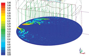
It is possible to observe how high the re-entrained droplets created by wave shear from the free surface will travel by injecting droplets from the free surface at the vertical upward velocity computed using CFD. Fig. 12 shows larger-size droplets traveling a short distance before falling back. If the gas velocities observed or calculated exceed either of these two criteria, then it is recommended that a wire mesh pad be placed below the inlet flow device to prevent re-entrant droplet from being carried off by the gas stream, or the HHLL from being lowered by the increasing tangent-to-tangent height of the vessel.
|
|
|
Fig. 12. Liquid droplet re-entrainment from free surface not |
Sizing the gravity section. The separation efficiency of the gravity section is calculated from the droplet force balance. Separation is governed by Stokes’ law, which states that the droplets dispersed in a continuous phase will settle if the downward-acting force of gravity is greater than the sum of drag around the assumed spherical droplet and greater than buoyancy, due to thermal gradients (if present). This law is valid only for Reynolds numbers from 0.1 to 0.3. Unless the K factors are extremely low, it is very likely that there will be no liquid separation in this section.
The basic equation for terminal settling velocity, Vt, is given in Eq. 7:
![]() (7)
(7)
where:
D=Droplet diameter, ft
µ=Gas viscosity, lb/ft/s
ρl=Liquid density
ρg=Continuous phase density.
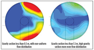
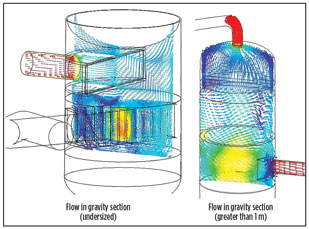
In most vessels, especially slug catchers where designs are based purely on gravity separation, the diameter of the vessel and the height of the gravity section should be determined while keeping K factors to a minimum.
The Souders-Brown k-factor is given in Eq. 8:
![]() (8)
(8)
where Vmax = Maximum velocity.
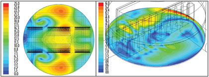
A properly sized gravity section is typically the height of one vessel diameter, and allows the flow to redistribute and even out the distribution at the mist eliminator entry. The flow fields at the mist eliminator entry for an undersized gravity section, and for one of sufficient height, are shown in Fig. 13. Vertical cross-section vectors are shown in Fig. 14.
|
|
|
Fig. 13. Flow fields at mist eliminator entry for an |
|
|
|
Fig. 14. Vertical cross-section vectors. |
Mist eliminator considerations. A mist eliminator may contain several of the following elements:
- A vane pack made up of corrugated plates with or without pockets (pocketed vanes) to collect larger liquid droplets
- A wire mesh demister consisting of a wire mesh of intertwined wires with high surface density and high void fraction to collect smaller droplets
- A perforated plate to impose a pressure drop.
The wire mesh agglomerates small droplets into larger ones and captures smaller droplets. The vane pack then captures the larger droplets.
The droplet capture efficiency and the wire mesh/vane pack droplet handling capacity and k-factors given in the device supplier hydraulic calculations are usually obtained from test data using air/water systems at lower pressures and ambient temperatures.
Suitable derating parameters using Weber and Froude numbers must be calculated for different fluids with different gas/liquid density, viscosity, surface tension, operating pressure and temperature to re-estimate actual liquid carryover and droplet removal efficiency of the mist eliminator system. Typical mist eliminators take water liquid load of 1 gpm/ft2 derated to 0.5 gpm/ft2 for liquid hydrocarbon.
Mesh mist eliminator. With high void fraction, wire mesh or knit mesh may reduce liquid carryover by 100th of the order of 10µ, and larger droplets without any large pressure drop. Mist consists of droplets in the submicron range (< 3µ), while 10µ and higher would be a spray. A typical wire mesh pattern is shown in Fig. 15, with droplet coalescing at the junction of two wires. Also shown is a typical mist eliminator, consisting of a coarse and fine wire mesh followed by a vane pack and perforated plate (right).
|
|
|
Fig. 15. A typical wire mesh pattern (left), with droplet coalescing at the junction |
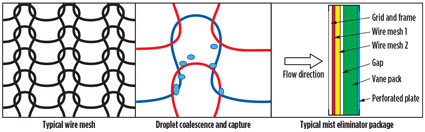
Passing through the wire mesh, smaller droplets adhere to the wire, coalesce and form larger droplets. The larger droplets are driven down by gravity and are collected by a drainpipe, plates or V-shaped channels.
Vane pack. Vanes can be engineered to operate at higher gas velocities and flowrates relative to the mesh. The efficiency may drop off drastically at low velocities, mainly due to the fact that droplets will drift around the mesh filament and blades without touching or adhering to the surface.
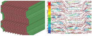
If the velocity is too high, then the droplets are captured; however, the higher flow will essentially overcome the surface tension forces of droplets adhering to the solid surface and re-entrain them back into the gas stream. Vanes may be of the corrugated variety, or they may even have pockets to capture droplets, as shown in Fig. 16.
|
|
|
Fig. 16. Pocketed vane pack and related flow field. |
Enhancements for minimizing vessel size. For compressor suction drums that use refrigerant, the low-, intermediate- and high-stage units are usually designed as one vessel, with a unit for each stage placed on top of one another. The vessel size is governed by the low stage due to larger flowrate and liquid content.
To keep the vessel diameter constant for all three stages, the intermediate and high stages are most likely oversized and will not require a stringent analysis to predict liquid carryover. To conserve space, the low-stage mist-eliminator unit (usually a vertical box called four-bank housing) has four vertically placed mesh pads, a vane pack and perforated plate combinations at each face, as shown in Fig. 17.
|
|
|
Fig. 17. Four-bank housing (a); side-to-side flow field (north to south) (b); crossflow |
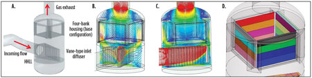
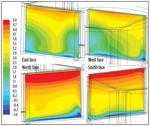
If the direction in which flow enters the vessel is taken as the east direction (as referenced in Fig. 6), then there is more flow to the north and south faces of the four-bank housing (Fig. 17A) compared to east and west faces (Fig. 17C). Furthermore, the cramped space between the housing and the vessel wall forces flow toward the upper quadrant, causing a large velocity gradient across the face of the mist eliminator (Fig. 18). This situation leads to high peak k-factors and localized flooding. The contour plots also show some flow redirected back into the vessel at the bottom of the housing, which has a negative effect on liquid removal efficiency.
|
|
|
Fig. 18. Normal velocity contours at entry to each face of |
To mitigate the flaws in design, some improvements are recommended for four-bank housing:
- Rotate the four-bank housing by 45° about its vertical axis, which will result in the front faces of the mist eliminator facing northwest, southwest, southeast and northeast
- Change the dimension of the housing, allowing a total gap area that is at least greater than three times the area of the inlet nozzle, to reduce the approach velocities.
These changes alone may not be sufficient to provide a uniform velocity profile to each of the four sides. A third mitigating effort is to adjust the open area of the downstream distribution baffle. Each perforated plate may be split horizontally, into as many as four sections, as shown in Fig. 17D. By using less net-free-area (NFA) baffles at the top (thereby restricting flow and higher velocities to the upper segment) and gradually increasing the NFA toward the bottom, a more uniform flow distribution may be obtained at each face. This may even reduce the reversed flow, which is highly detrimental to a liquids separation system.
The most effective method is to perform iterative CFD by using various combinations of pressure drop vs. superficial velocity, using the Ergun equation4 or Smith and Van Winkle equation.5 Intermediate normal velocity contours may be plotted to check for optimally uniform intake flow fields. The calculated NFA are used to fabricate the perforated plate sections.
Exit nozzle considerations. The diameter of the outlet may be sized so that the overall pressure drop does not exceed the process design parameters, and the velocity of the gas flow does not exceed the inlet pipe velocity as it exits the system. A suggestion is to use a diameter that is at least three-fourths the size of the inlet diameter.
The liquid outlet at the bottom head of the drum should be sized so that the exiting liquid velocity does not exceed 2 m/s, to prevent vibration and surge-related issues. Sometimes, a filter basket with grating, a bucket, and a weir and panel are used if solids and heavy liquids are expected to be removed.
Takeaway. A number of guidelines and considerations are available to meet design challenges encountered during the design of liquid/gas separators. The key criteria are to ensure uniform distribution at the mist eliminator entry and to maximize liquid removal efficiency.
Advanced simulation tools and empirical equations are used to ensure that the device is sized appropriately and operates as designed. GP
LITERATURE CITED
1Hinze, J. O., “Fundamentals of the hydrodynamic mechanism of splitting in the dispersion process,” AIChE Journal, Vol. 1, No. 3, September 1955.
2Kouba, G. E., “Mechanistic models for droplet formation and breakup,” Proceedings of the ASME/JSME 4th Joint Fluids Summer Engineering Conference, Honolulu, Hawaii, July 6–10, 2003.
3Wallis, G. B., “The onset of droplet entrainment in annular gas-liquid flow,” Report No. 62GL127, General Electric Co., Schenectady, New York, 1962.
4Ergun, S. and A. A. Orning, “Fluid flow through randomly packed columns and fluidized beds,” Ind. Eng. Chem., June 1949.
5Smith, P. L. and M. Van Winkle, “Discharge coefficients through perforated plates at Reynolds numbers of 400 to 3,000,” AIChE Journal, Vol. 4, No. 3, 1958.
 |
Jaleel Valappil is a principal process engineer and team lead for the advanced simulation group of Bechtel Oil, Gas and Chemicals in Houston, Texas. His areas of expertise include process engineering, simulation, control and optimization. He is responsible for developing and deploying advanced technical solutions during design, commissioning and operation of various Bechtel projects, including LNG terminals. Dr. Valappil holds a bachelor’s degree from the Indian Institute of Technology in Kharagpur and a PhD in chemical engineering from Lehigh University in Bethlehem, Pennsylvania.
 |
Philip Diwakar is a senior engineering specialist at Bechtel with 23 years of experience in CFD, FEA and acoustic- and flow-induced vibrations. He is a lead specialist in Houston, Texas, responsible for providing solutions for warranty-, environment- and risk-related issues covering several of Bechtel’s business units. To his name, Mr. Diwakar has more than 25 publications, six outstanding technical paper awards, three journal publications and an innovation award for fluid-structure interaction. He has also received technical grants for the design of buildings to withstand explosions in LNG plants, thermal fatigue in dehydrators, fume gas treatment and acoustically induced vibration.


Comments