Smart design for high CO2 removal for natural gas production
G. Bowerbank, Shell Global Solutions, Amsterdam, The Netherlands
Recent oil and gas discoveries provide an increasing outlook for gas fields containing CO2 content of 10 mol% to as high as 70 mol% of CO2. The increasing amount of CO2 content in newly discovered gas fields requires smart designs to minimize capital and operational expenditures (CAPEX and OPEX) while adhering to emissions requirements.
Amines and membranes are commercially available technologies for CO2 removal. However, membranes alone can only perform bulk CO2 removal and cannot achieve low CO2 specifications (and certainly not the deep CO2 removal needed for LNG specifications). Therefore, membranes will often require an amine unit to meet the CO2 specification as a polishing step.
Here, a case study based on amine technology is discussed. Amine technology is a well-proven process for CO2 removal and is capable of meeting these stringent specifications, but it comes with high CAPEX and OPEX at the increased levels of CO2.
In this study, a smart design involving a pioneering approach was undertaken. The design resulted in a 30% reduction in OPEX, and it captured a CAPEX gain of 24% against a conventional amine design.
Introduction. As more high-CO2 fields are being explored across the globe, there is an increasing demand to develop new technologies or modifications of existing technologies to perform several functions:
- Reduce CAPEX
- Reduce lifecycle cost
- Reduce CO2 footprint
- Provide a competitive alternative for membranes
- Simplify the design
- Enable the development of high- CO2 fields.
In this case study, the “standard” process design lineup is compared against a “smart design” lineup.
The CAPEX and OPEX performances are compared to evaluate the potential benefits of smart design. The results suggest significant value additions for new plant designs, while, for existing plants, they open up debottlenecking opportunities.
The CO2 in feed gas in this study was as high as 20 mol%, and the treated gas specification of 50 ppm was to be achieved for a 4-MMtpy LNG plant. The sour gas is treated with aqueous amine to achieve the required specification. The simulations are performed with a proprietary simulation tool. Air cooling is considered as a cooling medium in this case study to cool the process streams to 44°C. Alternative cooling media were not considered. A standard process lineup is shown in Fig. 1.
 |
|
Fig. 1. Standard process lineup for amine treating for LNG production. |
Study outline. Methyldiethanolamine (MDEA) is a tertiary amine (represented as R3N) and, as per the reaction stoichiometry shown in Eqs. 1–4, every mole of MDEA can absorb 1 mole of CO2. Therefore, the theoretical maximum rich loading would be 1 mol of CO2/mol of MDEA.
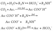
Normally, the maximum rich loading is limited to approximately 0.6 mol/mol to avoid corrosion issues with the carbon steel equipment. Higher rich loadings are often not a concern, as an alternative suitable material can be used. However, the column bulge temperature itself causes an equilibrium pinch in the bulge, which stops further CO2 removal.
The CO2 absorption in amines (MDEA + piperazine) generates heat, often termed as heat of absorption, or dH. The CO2 absorption in MDEA is a very slow reaction (bicarbonate), while the addition of an activator (piperazine) enhances the CO2 absorption capacity significantly. This enhancement is due to the fact that piperazine encourages faster bicarbonate (HCO3–) formation.
As the CO2 in the feed gas increases, the relative quantity of CO2 absorbed per ton of solvent increases. This results in a temperature profile within the column, such that equilibrium is reached and further CO2 removal is hindered.
Operating at higher temperatures requires more expensive materials (alloys) to avoid corrosion. Traditionally, this requires that either the solvent flowrate be increased or the solvent be cooled to quench column temperatures. However, solvent cooling is limited to at least 5°C above hydrocarbon dewpoint to avoid hydrocarbon condensation. The increase in solvent flowrate will increase the CAPEX, while the cooling of solvent will mostly impact the OPEX. The most credible and affordable option is to choose a path that will balance out the CAPEX and OPEX.
The smart design lineup approach is to reach the highest possible rich loading and to try to get as close as possible to the theoretical limit of 1 mole of amine for every mole of CO2 absorbed. Here, increasing the rich CO2 loading is the target, which can be achieved by removing heat from the absorber.
 |
|
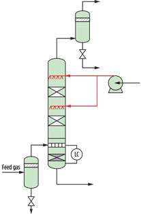
Fig. 2. Split flow process lineup. |
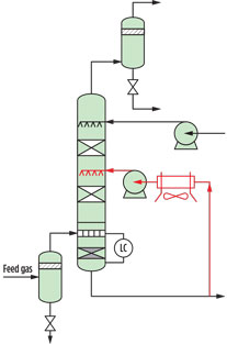
Various process lineups were assessed in this study (split flow, recycle, interstage cooling, etc.). The study showed that the interstage cooler lineup was the most competitive lineup, with significant CAPEX and OPEX reduction. Fig. 2 shows the split flow process lineup, and Fig. 3 showsthe recycle flow process lineup.
 |
|
Fig. 3. Recycle flow process lineup. |
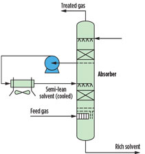
Application of processes. In the smart design lineup, semi-rich solvent from the upper section of the absorber is cooled to a minimum level to avoid hydrocarbon condensation, and then pumped back to the lower section of the absorber. Lower temperature will favor CO2 mass transfer toward the liquid phase and prevent equilibrium constraints from restricting the CO2 removal. This ensures that higher CO2 loadings are achieved and solvent circulation is reduced.
The partially loaded solvent from the upper section is cooled to a temperature still above hydrocarbon dewpoint and then pumped back to the lower section of the absorber, as shown in Fig. 4. The partially loaded solvent will have a greater driving force to absorb more CO2 due to the lower temperature, and mass transfer of CO2 into the liquid phase will increase. This process results in higher CO2 rich solvent loading, potentially as high as 0.85 mol/mol.
 |
|
Fig. 4. Process lineup modification in |
The smart design concept resulted in reduced solvent circulation that decreases the overall footprint of the plant. An additional heater and flash vessel are considered to flash off part of the CO2 in the flash drum upstream of the regenerator. This will result in lower CO2 loading of the solvent entering the regenerator, thereby keeping the regenerator column diameter as small as possible. This heat duty can be optimized to leverage benefits in the regenerator reboiler. This scheme is advantageous as the CO2 content in the feed increases.
The flash gas from the flash drum is at low pressure and high temperature, which can be attributed to significant loss of water vapor in the flash drum; therefore, the flash gas was routed through the regenerator overhead condenser. This routing avoids the need for a separate cooler and reduces water losses. The final process lineup for the smart design is provided in Fig. 5.
 |
|
Fig. 5. Smart design lineup. |
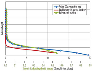
Data and results. In Fig. 6, the actual CO2 concentrations, equilibrium CO2 concentrations and the rich solvent loadings for the standard lineup are presented. The difference between the actual CO2 from the tray and the equilibrium CO2 provides the driving force. Larger differences are preferred for bringing about CO2 mass transfer from the gas to the liquid phase. The solvent rich loading gives us moles of CO2 absorbed per mole of amine circulated. The maximum rich loading achieved in this case is approximately 0.6 mol/mol.
 |
|
Fig. 6. Actual CO2, equilibrium CO2 and rich loading, |
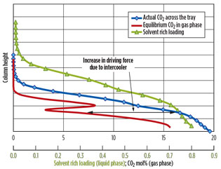
In Fig. 7, the actual CO2, the equilibrium CO2 in the gas phase, and the rich solvent loading are presented for the interstage cooler option. The shift in equilibrium due to the cooling of the solvent is highlighted. The cooling of the semi-rich solvent increases the difference between the actual and equilibrium CO2 partial, thereby aiding in CO2 mass transfer from the gas phase to the liquid phase. A maximum rich loading of approximately 0.8 mol/mol is achieved in this case, compared to approximately 0.55 mol/mol in a standard lineup.
 |
|
Fig. 7. Actual CO2, equilibrium CO2 and rich loading, |
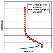
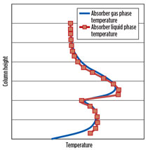
Figs. 8 and 9 show the respective column temperature profiles for the standard lineup and the interstage cooler lineup. In the interstage cooler lineup, there is a shift in bulge temperature upward with the addition of another, smaller bulge. This lineup can be further optimized based on the bulge temperature and the placement of the interstage cooler at the optimum level.
 |
|
Fig. 8. Column temperature profile, |
 |
|
Fig. 9. Column temperature profile, |
An additional heater and flash drum will help lower the rich loading to decrease the reboiler load. Additionally, routing the flash gas through a common overhead system will reduce equipment count and water losses. It will also help limit the regenerator column diameter, which is determined by the stripping steam generated inside the reboiler(s).
In terms of OPEX, the reduction in power consumption (pumps and air cooler) for the interstage cooler option is 20%, while the heat duty (reboiler plus heater) is reduced by 25% as compared to a standard lineup. CAPEX reduction occurs on a case-by-case basis.
The CAPEX free on board (FOB) cost is reduced by 15%, and the total installed cost (TIC) is reduced by 25% with the interstage cooler option as compared to the standard lineup. Due to the reduction in solvent flowrate, a step change occurred in the number of parallel regeneration sections (regenerators, reboilers, coolers, etc.). Despite the addition of an intercooler, a pump and a heated flash, the overall equipment count was reduced.
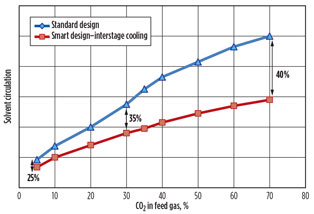
This study also examined the impact of the smart design lineup on changes in CO2 feed content. The results are presented in Fig. 10. The performance predicts that 10 mol% of CO2 feed content can yield a solvent circulation reduction of approximately 25%, while a feed content of 70 mol% can yield a reduction of up to approximately 40%.
 |
|
Fig. 10. Benefits of smart design with varying CO2. |
Recommendations. Smart designs that combine interstage cooling and a heated flash offer a competitive alternative to both existing and new plants. For existing plants, this can add 30%–40% additional savings with increased throughput by debottlenecking.
However, for new designs, this could bring in lower lifecycle costs with faster returns on investment. As the CO2 content goes up, the benefits could be higher; with lower CO2 content (e.g., approximately 10%), a minimum OPEX reduction of 15%–20% is observed.
The extra investment around the interstage cooling will pay off in the overall equipment size reduction and OPEX reduction. GP
 |
Gary Bowerbank has more than 14 years of experience in gas processing, both in the upstream and downstream businesses. He is the team lead for Shell Global Solutions’ gas processing external design team supporting Europe, the Middle East, Africa and Russia. Prior to this role, he was a senior gas treating technologist in Bangalore, India, where he served as technical lead for third-party gas processing licensing work in Asia-Pacific and supported major Shell gas processing projects and operating sites. Prior to this, he worked on amine, caustic, sulfur and hydroprocessing units at a JV refinery. He graduated in 2001 from the University of Manchester Institute of Science and Technology in the UK with an MEng degree in chemical engineering. He is a chartered engineer (MIChemE/CEng) and a Shell subject matter expert in gas treating operations.


Comments