
Optimize amine process design using liquid-phase turbochargers
P. Krish, J. Martin and M. Shirazi, Energy Recovery, San Leandro, California;
and J. Thorp, Aramco Services Co., Houston, Texas
Acid gas removal is a critical process step in natural gas processing and syngas production for ammonia and other uses. The application of a liquid-phase turbocharger to the acid gas removal unit (AGRU) results in significant energy savings and an improvement to the reliability, availability and maintainability (RAM) of the plant.
Here, conventional configurations with high-pressure pumps and new configurations utilizing liquid-phase turbochargers are described. The design of the equipment, process operations and controls, and reliability analysis are included. The results of a RAM study comparing conventional configurations to those incorporating liquid-phase turbochargers in multiple cases are also presented. From the RAM study, it can be concluded that flowsheet configurations that include a liquid-phase turbocharger consistently provide lower plant downtime and maintenance costs as compared with conventional flowsheet configurations.
These conclusions are in addition to the energy savings that result from energy recovery with the application of the liquid-phase turbocharger to the AGRU. For the reference plant used in the study, the maintenance cost savings are as great as
$2.5 MM over the 20-yr lifetime of the plant, and the average annual downtime reduction is as much as 19.8 hr.
Natural gas is an abundant, reliable and clean-burning source of energy that is typically processed to remove acid gases, such as carbon dioxide (CO2) and hydrogen sulfide (H2S), before it is ready for distribution and use. A common acid gas removal (AGR) process uses an amine solvent to absorb acid gases in a high-pressure contactor column. The pressure is then decreased for acid gas stripping in the regenerator.
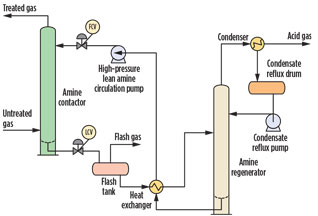
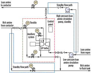
The opportunity exists to use a liquid-phase turbocharger to recover the energy wasted in the pressure letdown and transfer it to the low-pressure amine exiting the regenerator. This eliminates the need for a high-pressure pump, providing energy savings and maintenance savings, and positively impacting plant availability. Fig. 1 is a simplified process flow diagram of a typical AGRU.
 |
|
Fig. 1. Simplified process flow diagram of a typical AGRU. |
AGR process scheme. In an amine-based AGR process, the contactor column typically operates at pressures up to 1,100 psi (76 bar), and the amine regenerator operates at pressures closer to atmospheric.
The contactor column is operated so as to maintain a liquid pool of amine at the bottom of the contactor, with the untreated gas entering the column above this liquid level. Maintaining the liquid level becomes a critically important operational requirement. The gas must be forced to move up the column and out, rather than exiting the bottom of the column and moving toward the flash tank.
The high-pressure lean amine circulation (HPLAC) pump pressurizes the lean amine to some level above the contactor column pressure, and the flow into the column is controlled by a flow control valve (FCV), which throttles the flow from the HPLAC pump. These pumps are typically multistage centrifugal pumps. Multistage centrifugal pumps require significant regular maintenance and are subject to multiple failure modes, including those related to seals, couplings and external oil lubrication systems. To minimize the risk of plant downtime, these pumps are commonly installed in a redundant configuration.
Conventional flowsheet and redundancy configurations. To ensure continuous operation of the plant and to avoid the possibility of unplanned shutdowns due to equipment failures, equipment redundancy is engineered into the plant design.
LCV redundancy is typically achieved by using a standby LCV in parallel with the operating LCV. Each LCV is a “fail-close” device, meaning that, if failure occurs, the valve will close. The standby LCV would then open up to maintain the level control function. LCVs tend to be reliable, with mean time between failures (MTBF) in excess of 30 yr.1
Due to the relatively high capital expense associated with pumps, a second redundancy configuration is often considered. In this second configuration, three identical pumps are used. Each pump is sized to provide the full pressure boost required for contactor column operation, but with only half of the flow required. Two of the pumps are in operation at any given time, and the third pump is on standby. In the case of a pump failure of any one of the operating pumps, the standby pump comes online to maintain flow to the contactor.
The first configuration of two full-size pumps—one operating and one on standby—is referred to here as the 2 × 100% configuration, and the second configuration of three half-size pumps—two operating and one on standby—is referred to here as the 3 × 50% configuration.
Hydraulic turbocharger design and performance. The hydraulic turbocharger is a hydraulic turbine connected via a common shaft to a single-stage pump, within a single casing. The hydraulic design of the turbine side and the pump side are custom engineered using computational fluid dynamics (CFD) programs and design heuristics to best suit the process conditions of the particular application.
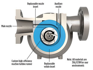
Of particular interest is the hydraulic design of the turbine side. Fig. 2 shows a schematic of the turbine side. Key design features of the turbine side include:
- A primary turbine nozzle directing incoming flow to the turbine volute
- An auxiliary nozzle also directing incoming flow to the turbine volute
- Replaceable volute inserts custom designed for the particular application.
 |
|
Fig. 2. Schematic of the turbine side of the hydraulic |
The flow directed to the auxiliary nozzle is controlled by an actuated valve—the auxiliary nozzle valve—so that the minimum flow to the turbine is with the auxiliary nozzle valve fully closed, and the maximum flow to the turbine is with the auxiliary nozzle valve fully open.
Actuating the valve between open and closed allows for 10%–15% flow turndown capability. The most common alternate turbine design that allows for flow turndown is a variable geometry turbine utilizing guide vanes or wicket gates. The addition of multiple actuated mechanical components, the guide vanes, affects the reliability of this alternate design.
 |
|
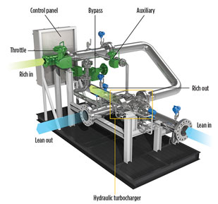
Fig. 3. Schematic of the hydraulic turbocharger system |
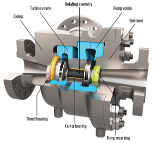
Fig. 3 is a schematic of the hydraulic turbocharger, showing the turbine and pump sides, with their respective inlets and outlets. Fig. 4 is a schematic showing the internals of the hydraulic turbocharger.
 |
|
Fig. 4. Schematic showing the internals of the hydraulic |
The turbine runner and the pump impeller are on a common shaft, intentionally designed to be very stiff with a low lift-to-drag ratio, and supported on a center (journal) bearing. Application of the hydraulic turbocharger in AGR processes is discussed in the next section, but for the purposes of this discussion, it should be understood that the pressure of the low-pressure lean amine entering the pump side of the hydraulic turbocharger is typically higher than the pressure of the low-pressure rich amine leaving the turbine side of the hydraulic turbocharger.
Therefore, a net thrust force is present from the pump side toward the turbine side, necessitating a thrust bearing on the turbine runner. Both the center bearing and the thrust bearing are lubricated by the process fluid, eliminating any requirement for external oil lubrication systems. Startup procedures require that flow begin on the pump side. The rotating assembly (RA) will not have torque applied until flow and pressure are present in the turbine, at which point bearing lubrication has been achieved.
During normal operation, the high-pressure lean amine stream exiting the hydraulic turbocharger is of sufficient pressure to lubricate the bearings and is directed toward the thrust and the center bearings. This fluid, constituting approximately 0.5% of the flow, is preferably filtered prior to injection into the bearings to safeguard against the possibility of particulate material entering the bearings. The center journal bearing lubrication scheme ensures that no rich amine fluid can contaminate the lean amine, so that contactor effectiveness is maintained.
The rotational speed of the hydraulic turbocharger is unconstrained and is allowed to vary according to the balance of hydraulic conditions on the turbine and the pump sides. This self-regulating mechanism ensures extremely low radial bearing loads and low vibration, and minimizes the risk of the related failure modes, such as shaft deflection, shaft unbalance, mechanical noise or thrust bearing failure. No overspeed protection is needed.
In the event that the pump load is momentarily significantly decreased (i.e., the pump outlet is shut off), the design and geometry of the system is such that the RA will operate below any critical speed and will not be damaged.
The fluid energy transfer efficiency is a key performance parameter of the hydraulic turbocharger. This parameter is defined as shown in Eq. 1:
Efficiency = [Qp × (Pp,out – Pp,in)]/[Qt × (Pt,in – Pt,out)](1)
A well-designed hydraulic turbocharger will typically have hydraulic efficiencies in the range of 60% to 80%, with larger hydraulic turbochargers operating at higher hydraulic efficiencies. This efficiency directly characterizes the transfer of energy from fluid stream to fluid stream, as compared to the efficiency of a hydraulic power recovery turbine (HPRT), where the efficiency is characterized as fluid stream to shaft power.
The design of the hydraulic turbocharger has certain inherent advantages from a reliability viewpoint as compared to traditional rotating equipment:
- Since there is no shaft exiting a casing, there is no requirement for shaft seals
- No requirement exists for an external oil lubrication system
- No couplings are present, and no requirement exists for alignment
- The rotating assembly is not speed constrained, as it does not share a common shaft with a fixed-speed pump
- Very low vibration.
As a result of these factors, the reliability of the hydraulic turbocharger exceeds that of a centrifugal pump. Consequently, replacing or reducing the duty of a centrifugal pump through the application of a hydraulic turbocharger has the effect of improving plant performance.
Alternative flowsheets using hydraulic turbochargers. Hydraulic turbochargers can be used in AGR processes by utilizing the energy in the rich amine, leaving the contactor to drive the turbine side of the turbocharger and thereby delivering the energy to the pump side to boost the pressure of the lean amine. In this process, the LCV is essentially replaced by the turbine side of the hydraulic turbocharger. A key requirement in this replacement is that the level control functionality of the LCV be maintained.
Prior designs using hydraulic power recovery turbines (HPRTs) in AGR processes required the turbines to operate at a fixed speed, and, consequently, at a fixed liquid flowrate. This requirement is necessitated by the fact that the turbines were typically clutch-coupled to a pump and a motor running at synchronous speed. Contactor-level control was then accomplished by passing a portion (typically 90%) of the rich amine contactor effluent through the turbine at a fixed rate and using the remaining 10% of the flow to control the level in the contactor.
In cases where contactor operation requires flow control beyond this 10% band, the HPRT is simply taken offline by disconnecting the clutch and allowing the motor to take the full load of pumping the lean amine to contactor pressure.
As described previously, the hydraulic turbocharger has a turndown capability of 10% to 15% through the adjustment of the auxiliary nozzle valve. This turndown capability may then be used to achieve contactor level control. In the event that contactor operation requires flow control beyond this 10% to 15% band, alternative measures are required to achieve contactor level control.
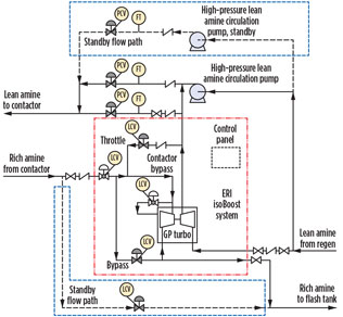
Fig. 5 shows a simplified process flow diagram of a hydraulic turbocharger in an AGRU, where a 2 × 100% redundancy configuration is utilized. In this configuration, the full effluent from the contactor is directed toward the turbine side of the hydraulic turbocharger, and the full flow of the lean amine is pressure-boosted by the pump side of the hydraulic turbocharger.
 |
|
Fig. 5. Simplified process flow diagram of a hydraulic |
Since the fluid-to-fluid efficiency of the hydraulic turbocharger is approximately two-thirds, and the flows on the turbine side and the pump side are essentially similar, approximately one-third of the required pressure boost is provided by a low-pressure lean amine circulation pump, which delivers fluid to the pump inlet of the hydraulic turbocharger.
Fig. 5 also shows three control valves associated with the hydraulic turbocharger: a throttle valve upstream of the turbine inlet, an auxiliary valve controlling flow to the secondary turbine inlet, and a bypass valve enabling flow to bypass the turbine side of the hydraulic turbocharger. The throttle valve is sized to accommodate the entire flow from the contactor and to provide a partial pressure drop; the auxiliary valve is sized to accommodate 10% to 15% of flow; and the bypass valve is sized to accommodate approximately 20% of the flow. These three valves modulate to control the contactor level in response to the plant amine contactor level controller output signal.
When the contactor level controller sends an increase-level signal within the normal operating range, the auxiliary valve will close. This reduces flow to the turbine and causes the contactor level to increase. When the contactor level controller sends a decrease-level signal, the throttle valve is incrementally opened.
Next, the auxiliary valve is incrementally opened to increase flow. If yet more flow is required, then the auxiliary valve is fully opened, and the bypass valve will be incrementally opened to allow more flow to bypass the hydraulic turbocharger. In normal operations, where a 10% to 15% turndown is sufficient to achieve contactor level control, the auxiliary valve achieves control with the throttle valve fully open and the bypass valve fully closed.
Fig. 6 shows a simplified process flow diagram of a hydraulic turbocharger in an AGRU, where a 3 × 50% redundancy configuration is utilized. A conventional multistage centrifugal pump provides the 50% redundancy fulfilment.
 |
|
Fig. 6. Simplified process flow diagram of a hydraulic |
As in the previously described configuration, the full effluent from the contactor is directed toward the turbine side of the hydraulic turbocharger, while approximately half of the lean amine flow is pressure-boosted by the pump side of the hydraulic turbocharger. The other half of the lean amine flow is provided with the full required boost by an HPLAC in parallel with the pump side of the hydraulic turbocharger.
This configuration utilizes an asymmetric hydraulic turbocharger where the turbine side is sized for approximately twice the flow as the pump side. Given that the efficiency of the hydraulic turbocharger is approximately two-thirds, more than adequate energy exists in the turbine-side flow to provide the full required boost to the half flow on the pump side. In this configuration, there is no low-pressure lean amine circulation pump, and the only requirement is that the pump side of the hydraulic turbocharger be provided with adequate suction pressure to operate reliably without cavitation. The contactor level control is achieved in much the same manner as in the previously described 2 × 100% configuration.
Centrifugal pump and hydraulic turbocharger reliability. A hydraulic turbocharger can replace a conventional API 610 multistage centrifugal pump in an AGRU. This replacement leads to a change in overall system reliability and plant availability. The calculation of the new system reliability will vary by process and by equipment arrangement.
The input to the revised system reliability can be quantified by the difference in reliability between the replaced centrifugal pump and the replacement hydraulic turbocharger. The centrifugal pump reliability, as defined by failure rate, or mean time to failure (MTTF), provides the baseline for analyzing the impact of the turbocharger on the reliability of the system.
While centrifugal pumps are generally considered to be reliable devices, they are complex, multi-component pieces of equipment that serve critical industrial applications where they are exposed to challenging fluids at high pressures. Regular maintenance is required, and it is standard to include redundancy on pumps to ensure that interruption of plant operation is minimized.
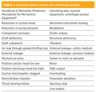
Multiple common failure modes exist for centrifugal pumps. Descriptions of these failure modes from two primary sources are presented: 1) The OREDA operating equipment database, and 2) standard pump reliability prediction procedures from the Handbook of Reliability Prediction Procedures for Mechanical Equipment.2 Table 1 summarizes common failure modes as defined by both sources.
The OREDA data had a population of 156, aggregated calendar time in service of 3.2412 MMhr, and operational time of 2.129 MMhr. The database provides failure modes and rates for critical failure modes and degraded failure modes.
While a root cause analysis on this dataset was not performed, we can use the reliability prediction equation (Eq. 2) for a predicted failure rate:
λP = λSE + λSH + λBE + λCA + λFD(2)
Detailed methodology for the determination of each of these component failure rates for specific equipment and operating parameters is provided. The correct determination of component failure rates is critical for an accurate result. However, it is informative to review the base failure rates to understand the relative impact of the components on failure rates. These rates are shown in Table 2.
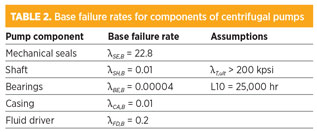
It can be seen that the components most likely to be responsible for failure are mechanical seals, which aligns with industry experience and knowledge.3 Even with the best materials and technology available, mechanical seals are difficult to design and manufacture to meet the demanding needs of rotating equipment.
Although they are significantly less complex than API 610 multistage pumps, hydraulic turbochargers exhibit some of the failure modes common to rotating equipment. Bearing systems, used to provide reaction forces to imparted radial and axial loads, are life-limited components. The hydrodynamic journal bearings and hydrostatic axial thrust bearings typically utilized in these devices have a theoretically infinite life, provided the lubricating fluid is completely free of particulates. Since these bearings are typically lubricated by the process fluid itself, there is risk of bearing damage when the fluid is off-spec or contains entrained particulates.
Bearing damage can ultimately lead to equipment failure. Fluid filtration systems can be applied to the portion of process fluid being utilized for bearing lubrication, which will significantly enhance the reliability of the bearing system while adding minimal complexity. Since the pump impeller typically operates at very high speed and the depressurized process fluid at the turbine exit has a tendency to flash, hydraulic turbochargers can also sustain damage from cavitation.
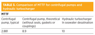
An MTTF estimation of hydraulic turbochargers is derived by two separate means, one being the evaluation of hydraulic turbocharger performance in desalination, where these devices have been in use for more than 20 yr; and another being the utilization of the OREDA database and removing failures from seals, gaskets and external couplings:
- Turbochargers in desalination. A study involving a large installed base (359 units) of turbochargers in seawater reverse-osmosis desalination service over a period of 17 yr (1996–2013) concluded that these units have a typical MTTF of greater than 10 yr. The MTTF was greater than expected, even though the application is relatively challenging due to the corrosive nature of the high-chloride process fluid, poorly constructed plants, and relatively unskilled operators as compared to typical oil and gas installations. Failures observed were mostly associated with debris in the process fluid and chloride crevice corrosion.
- OREDA data.1 On the removal of failures caused by seals, gaskets and external couplings from the OREDA data, it is found that MTTF extends from 2.9 yr to 8.9 yr. The qualification of failure types and related components is based on a root-cause analysis of the OREDA pump database. This result correlates well with the 10-yr MTTF of hydraulic turbochargers in desalination. A hydraulic turbocharger will share similar failure modes as related to impellers, changes in operating conditions and, potentially, bearings in a pump. The process-fluid-lubricated internal bearings in a turbocharger have a lower typical failure rate than do conventional bearings in centrifugal pumps, as they do not require an external bearing support system, such as oil mist lubrication, but are still a potential failure mode. Since hydraulic turbocharger design does not include an external shaft, shaft seals, gaskets or couplings, failure modes associated with these components do not apply.
A comparison of MTTF is summarized in Table 3. In reviewing this comparison, it is clear that the low part count and elimination of high-failure-rate components in the hydraulic turbocharger contribute significantly to its reliability advantage.
Hydraulic turbocharger DFMEA. As part of this study on hydraulic turbocharger reliability, a design failure mode and effects analysis (DFMEA) was performed as described in the emergent API standard 691, Risk-Based Machinery Management. The DFMEA identified three components of the design which had a relatively high “risk number” (a metric of the overall potential hazard inherent to the component).
Two of these components were bearings, which was not an unexpected finding given the critical role they play in rotating equipment and the variability of the process fluid used for lubrication. The other component is the bolt used to hold the two halves of the RA together.
This result was not anticipated by those performing the DFMEA. It proved the value of the exercise while providing an opportunity to upgrade the overall reliability of the system by modifying the design to reduce the likelihood of the failure mode occurring.
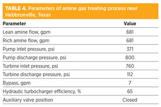
Field operating data. A hydraulic turbocharger has been operating in amine service since 2008 near Hebbronville, Texas. The sour gas treating facility uses a conventional amine gas treating process, with a high-pressure contactor operating at approximately 800 psi and a near-atmospheric regeneration section. The hydraulic turbocharger is installed in a 2 × 100% configuration, and is fed with a low-pressure lean amine circulation pump. A variable frequency drive (VFD) is used to control the amine flow into the contactor.
After initial startup in 2008, the turbocharger has run continuously, with no required maintenance or instances of failure. Table 4 gives the parameters of the system, including the original design and the new design with the hydraulic turbocharger.
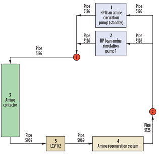
RAM modeling and lifecycle cost comparisons. To determine the impact of the change in component reliability on the system and plant, RAM modeling was performed using a Monte Carlo simulation technique. A system block diagram is created to represent the process flow diagram configuration, with each component of equipment represented in the block diagram. Fig. 7 shows an example block diagram used in the simulation.
 |
|
Fig. 7. Process flow diagram configuration for RAM modeling |
Reliability data for different system components are the required inputs for the simulation. Table 5 shows the MTTF for key components in the system.
Various configurations of equipment with and without hydraulic turbochargers are modeled using this technique:
- 3 × 50% base case: Three HPLAC pumps controlled by a common FCV, two pumps online and one on standby
- 3 × 50% configuration with hydraulic turbochargers: Two HPLAC pumps in parallel with one hydraulic turbocharger pump controlled by a common FCV; one pump and one hydraulic turbocharger online and one pump on standby
- 2 × 100% base case with VFD: Two HPLAC pumps in parallel, controlled by dedicated VFDs; one pump online and one pump on standby
- 2 × 100% base case with FCV: Two HPLAC pumps in parallel; flow to the contactor controlled by a flow control valve (FCV); one pump online and one pump on standby
- 2 × 100% configuration with hydraulic turbochargers with VFDs: One HPLAC in parallel with one hydraulic turbocharger being fed by a low-pressure lean amine circulation pump, and both pumps being controlled by VFDs; one hydraulic turbocharger online and one pump on standby
- 2 × 100% configuration with hydraulic turbochargers with FCVs: One HPLAC in parallel with one hydraulic turbocharger being fed by a low-pressure lean amine circulation pump; flow to the contactor controlled by a flow control valve (FCV); one hydraulic turbocharger online and one pump on standby.
The Monte Carlo simulation of these cases is performed to convergence over a 20-yr plant lifecycle, and lifecycle costs (LCCs) are evaluated for a reference plant. The reference plant for this analysis is a large gas processing plant with a normal lean amine circulation flow of 5,969 gpm and a rated flow of 6,565 gpm. The high-pressure lean amine circulation pump is specified as an electric-motor-driven API 610 BB3 pump with pump suction pressure of 166 psi and pump discharge pressure of 1,081 psi.
Results. The model was used to determine the overall reliability of a proprietary hydraulic pumping system. The system is reported to save energy in the CO2-removal process for ammonia production. This reliability determination was based on the proprietary liquid-phase turbocharger, as well as on defined expected pump maintenance costs. It highlighted the components that contributed to nonperformance, and quantified the design measures needed (redundancy, upgrades, etc.) to attain system reliability and availability goals.
The results of the modeling effort showed that all cases utilizing hydraulic turbochargers have lifecycle costs that are a fraction of the costs arising when hydraulic turbochargers are not used.
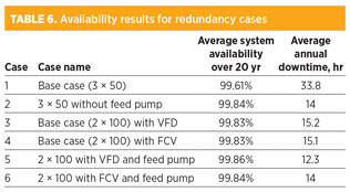
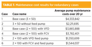
For the full redundancy cases, the average system availability over 20 yr ranged from 99.61% in the 3 × 50% base case, up to 99.86% for the 2 × 100% example with VFD and the hydraulic pumping system. Average pump maintenance costs across the same fully redundant cases ranged from a high of $4.3 M (3 × 50% base case) to a low of $1.4 M (2 × 100 with VFD and hydraulic pumping system feed pump). Tables 6 and 7 provide the availability and maintenance cost results.
Takeaway. Based on the results of this study, several conclusions can be drawn:
- Installation and maintenance of redundant pumping are critical for minimizing plant downtime and minimizing lost production.
- Installation and maintenance of redundant pumping do not have a significant impact on maintenance costs.
- Flowsheet configurations that include the hydraulic pumping system consistently provide lower plant downtime and maintenance costs as compared with conventional flowsheet configurations, not including the hydraulic pumping system.
- In the case of conventional flowsheet configurations (not involving the hydraulic pumping system), the 2 × 100% configuration provides a lower plant downtime and maintenance cost than the 3 × 50% configuration.
- In the case of flowsheet configurations that include the hydraulic pumping system, the 2 × 100% configuration with VFD provides the lowest downtime of 12.3 hr, as compared with 15.2 hr for the 2 × 100% configuration without the hydraulic pumping system.
- The largest difference between cases with and without the hydraulic pumping system is seen in the 3 × 50% configuration. The 3 × 50% configuration without the hydraulic pumping system shows the highest downtime of 33.8 hr. The 3 × 50% configuration with the hydraulic pumping system provides only 14 hr of downtime. Incremental lost production of approximately 19.8 hr/yr could have a financial impact in the $1.6-M range.
Hydraulic turbochargers are a beneficial and reliable alternative for the reduction of conventional pumping requirements in amine gas treating operations. Improved plant operations and availability are achieved as a result of improved component reliability and reduced maintenance. GP
LITERATURE CITED
1OREDA, Topside Equipment, Vol. 1, 2009.
2Handbook of Reliability Prediction Procedures for Mechanical Equipment, Naval Surface Warfare Center, Carderock Division, Department of the US Navy, May 2011.
3Marscher, W. D., “Avoiding failures in centrifugal pumps,” Proceedings of the 19th Annual Pump Symposium.
NOMENCLATURE
Turbocharger nomenclature:
Pp,outPressure at pump outlet
Pt,outPressure at turbine outlet
Pp,inPressure at pump inlet
Pt,inPressure at turbine inlet
QpPump side flow
QtTurbine side flow
General nomenclature:
σT,ultUltimate tensile stress
λPTotal pump failure rate
λSETotal failure rate for all pump seals
λSHFailure rate for the pump shaft
λBETotal failure rate for all pump bearings
λCAFailure rate for the pump casing
λFDFailure rate for the pump fluid driver
 |
Prem Krish served as the chief technology consultant at Energy Recovery Inc., bringing more than 25 years of product development experience to a career that has spanned Standard Oil of Ohio, British Petroleum, Carborundum, Dorr-Oliver, Avery Dennison and Inspectral Systems. In these roles, Dr. Krish conceived, developed and deployed new products and innovative production processes for a wide range of industries, including upstream and downstream petroleum, mining and mineral processing, ceramics manufacturing and petrochemicals.
 |
Jeremy Martin is the chief engineer at Energy Recovery, and the company’s expert in PX Pressure Exchanger technology, leading the development of the PX technology used in the company’s VorTeq system. Mr. Martin joined the company in 2005 and spearheaded the development of the IsoGen turbogenerator and IsoBoost turbocharger systems. Previously, he worked for Molex Inc., Paragon Products and TRC. Mr. Martin earned his BS degree in mechanical engineering from Cornell University.
 |
Max Shirazi is the applications engineering director at Energy Recovery. Dr. Shirazi has worked in various sectors, including oil and gas, pulp and paper, and specialty chemicals as a process engineer, engineering manager and project manager. He has led several greenfield and revamp projects in North America, Asia and the Middle East. Dr. Shirazi received his PhD from McGill University in Montreal, Canada.
Joseph Thorp is a machinery engineering consultant with Aramco-USA, involved in forensics, reliability modeling, process-machinery design optimization, and technology research and development. He was a 2006 recipient of the Aramco President’s Award for cost savings of over $100 MM in the optimization of the water-injection supply system on the Khurais Sea Water Expansion Project, which resulted in one of the largest incremental increases of crude oil to the world market in Saudi Aramco’s history. He is a former head of the USA delegation to the International Standards Organization (ISO) Technical Committee 67/SC6 and chairman emeritus of the API’s Subcommittee on Mechanical Equipment.


Comments