
Pair NGL recovery with LNG production to improve processing economics
D. Beck, Audubon Companies, Denver, Colorado
In recent years, the use of LNG as a clean-burning alternative to coal, gasoline and diesel has grown dramatically. However, this trend has been somewhat hampered in recent months as the price differential between crude oil and natural gas has narrowed.
Overall demand for natural gas throughout the globe is expected to rise steadily in the coming years. In light of this growing demand, the need for new and more efficient methodologies that can help producers deliver LNG to market quicker and cheaper has also increased.
Pairing LNG production facilities with NGL recovery plants has proven to be an effective way of delivering LNG to market. As the industry continues to shift away from large, multi-ton LNG facilities in favor of small-scale (micro) production operations that can better accommodate local markets, optimization of these systems will become increasingly important.
Present LNG production. The price of LNG is largely determined by three factors: the price of natural gas, the cost of liquefaction and the cost of transportation. Liquefaction makes up approximately 30%–40% of the total cost. By reducing the cost required to liquefy gas, the price of LNG can be decreased and passed on to operators as increased market share and/or profits.
The majority of today’s LNG production takes place at large-scale liquefaction plants. These facilities are designed to produce extremely large volumes of LNG. As a result, they often cost hundreds of millions of dollars to develop and require a large footprint, making them impractical in many areas of the world.
LNG is also used for peakshaving in natural gas power plants. When demand for power increases, the supply of natural gas from the pipeline may be insufficient. More recently, LNG has been used as a clean-burning alternative to gasoline and diesel in the trucking, railroad and marine markets. Conversion kits can be added to diesel engines to allow them to burn LNG in lieu of, or in combination with, diesel.
Why couple LNG with NGL recovery? Traditionally, NGL recovery and LNG production have been viewed in the marketplace as two separate segments. Upstream and midstream providers have typically focused on recovering NGL and producing a residue gas stream, while downstream providers have focused on using that gas stream to produce LNG.
With the current market and infrastructure in many regions of the world, however, this supply chain limits LNG distribution to a relatively small radius. As a result, LNG production is now migrating into the midstream arena in an effort to shorten the market distribution chain and broaden LNG availability, leading to more selling options for producers.
Small-scale, or micro, LNG facilities provide such distribution options when paired with natural gas processing plants. With larger LNG plants, exports are transported internationally via carriers to end users. With micro-LNG facilities, on the other hand, LNG production is distributed primarily within local markets where demand is high. In addition to significantly reducing capital costs, this methodology allows for much faster market penetration and has the potential to expand LNG opportunities into nontraditional markets and allow producers to exploit gas sources that were, at one time, considered uneconomical.
The biggest benefit of pairing NGL recovery with LNG production comes from the commonalities between the two facilities, as both require much of the same operating and utility units, including gas treating, power distribution systems, control systems, flares, water treatment systems and other ancillary infrastructure. Micro-LNG facilities also offer greater operational flexibility, along with lower capital and operating costs. By sharing the plant infrastructure, operators can save approximately 35%–45% on capital costs when compared to a standalone LNG plant. Similarly, operating cost savings are estimated at approximately 20%–30% when compared to two standalone units.
The regeneration gas disposal is another advantage of combining the two facilities. In a standalone LNG plant, one of the main process challenges is the disposal of the spent regeneration gas, which can contain CO2 and other impurities. In a standalone LNG plant, this spent gas can be both difficult and expensive to dispose of due to the limited options for removal. In an NGL plant, however, the spent regeneration gas stream can be easily managed with the use of the plant processing options via fuel gas or blending. These advantages are spawning a new generation of natural gas processing techniques that aim to transform LNG into a preferred fuel source.
Table 1 illustrates facility unit comparisons for a typical standalone NGL recovery plant and a standalone, mid-sized LNG plant. The middle column, “Common,” shows which systems can be shared and/or consolidated.
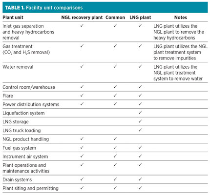 |
Design principles and challenges. Coupling an LNG plant with the backside of a cryogenic gas plant allows for the minimization of infrastructure costs by consolidating impurity removals and/or the pretreatment system equipment. Since LNG is essentially liquefied residue gas, the pretreatment requirements of an LNG unit are the same as a cryogenic gas plant. The primary difference is that LNG facilities require a higher-purity residue gas, which is not always produced from a standard cryogenic gas plant. The design of an LNG unit begins with the product specification. The typical product specification for LNG is shown in Table 2.
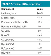 |
The composition shown in Table 2 closely resembles a typical residue gas product stream produced from an NGL plant using a gas subcooled process design in ethane recovery mode (note the low concentrations of CO2 and H2S). When coupling an LNG unit with a cryogenic gas plant, it is beneficial for the gas plant processes to handle the pretreatment requirements. As inlet gas conditions vary and the processing design parameters of the pretreatment systems are analyzed, an optimal design point can be identified. The LNG pretreatment component removal requirements, as compared to a typical gas subcooled process cryogenic design, are listed in Table 3.
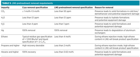 |
Due to the high degree of pretreatment required for LNG production, an evaluation of inlet gas treating, residue gas treating or both should be considered. The capital cost of enlarging the inlet CO2 removal vs. two separate CO2 removal units should also be investigated. Depending on the operational mode of the gas plant (ethane recovery vs. ethane rejection), compounds in the residue gas may need to be removed as well.
A typical methane number for LNG is 95. During ethane rejection, this specification could be breached due to the presence of ethane and/or other compounds in the residue gas. In this scenario, the liquefaction unit would need to be designed to remove ethane and hydrocarbons in an intermediate pass and recycled, or blended into one of the gas plant streams.
Since the cost per gallon of LNG proportionally decreases with the size of the LNG production plant, feed gas rates must also be taken into consideration. Table 4 provides a rough estimate of the LNG feed gas requirement rates for different-sized LNG units. The LNG production rate can be derived by extracting data from sales contracts, consumption estimates and project financing.
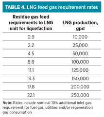 |
Design optimization. As discussed in the previous section, a number of design considerations must be taken into account when coupling an LNG facility on the back end of a cryogenic gas processing plant. CO2 and water specifications must be met prior to feeding the gas into the LNG liquefaction unit. Not ensuring that these specifications are met can lead to plugging and/or damage of the heat exchangers, causing serious performance issues for the facility.
The removal of water and CO2 from the gas stream can vary depending on a number of factors, including inlet composition, NGL CO2 product specification and sales gas pipeline specifications. In some cases, the best option (from both an economical and operational standpoint) may be to treat the entire inlet gas stream down to the desired CO2 specifications of less than 50 ppm. In other cases, it may be more beneficial to perform treating on the front end of the plant, with back-end treating for the NGL product and LNG feed to remove residual CO2.
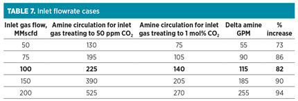
The analysis outlined in Table 7 can help determine a breakpoint between the two options. It is important to note that the purpose of the analysis is not to identify a design that will fit all applications, but rather to help producers determine a good configuration for their specific facility.
 |
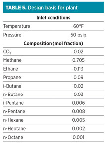
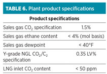
The design basis and plant product specifications shown in Tables 5 and 6 were used for all flow cases. The conditions listed below are meant to mimic a typical gas composition from a shale play (where coupling on a small LNG facility with a cryogenic gas plant is most likely to occur).
 |
 |
Various cases were reviewed to determine the best design for each scenario. The following options were investigated, and the results are discussed below:
- Option 1: 50-MMscfd, 75-MMscfd, 100-MMscfd, 150-MMscfd and 200-MMscfd gas plant and 100,000-gpd LNG with back-end CO2 removal
- Option 2: 50-MMscfd, 75-MMscfd, 100-MMscfd, 150-MMscfd and 200-MMscfd gas plant and 100,000-gpd LNG with front-end amine to < 50 ppm CO2.
For this analysis, the back-end treating technology selected was a molecular sieve that would remove the residual CO2 in the gas stream after cryogenic gas processing. A CO2 molecular sieve was chosen because it provided the simplest operating technology and the fewest pieces of equipment. A back-end amine treating unit would accomplish the same objective; however, it would also result in the need to install an additional amine absorber and a molecular sieve dehydration unit. The addition of these units would typically result in higher capital costs and greater operational complexity.
The cases were evaluated using key operational parameters as guides to determine the optimal configuration based on the inlet gas flowrate. The parameters identified included the amine circulation rate and the amine reboiler duty; these parameters are typically used to size amine units. Amine plants are usually rated by circulation rate and are sized with standard packaged units based on these rates. Table 7 shows the results of the key parameters identified above from the various simulations for each case.
Table 7 shows that the back-end treating (Option 1) results in a roughly 70% reduction in circulation rate, with the amine reboiler duty following a similar trend. An inflection point exists around 100 MMscfd, where the difference between the two options begins to grow at a much higher rate. This scenario suggests that, for a gas plant with an inlet rate greater than 100 MMscfd, back-end treating is the best option.
It is important to note that, if the inlet flowrate is greater than 100 MMscfd, a more detailed economic analysis would be required. This analysis would need to examine a complete total installed cost estimate for both options. It would also need to take into account operational costs and complexity. For example, the front-end treating option would require a larger amine unit, but would not require the additional equipment included in the back-end treating option.
For lower circulation rates, the increased size of the amine unit would offset the additional capital cost of a back-end molecular sieve unit. Additionally, the incremental operational costs of a larger amine unit would be offset by the operational costs of the regeneration unit for the molecular sieve. As discussed previously, however, once the inlet flowrate hits the inflection point of 100 MMscfd, both the capital costs and operational costs for the front-end case will be higher than those for the back-end treating option.
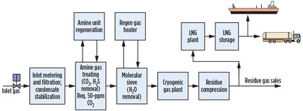
At this inflection point, it becomes more economical to only treat for CO2 in the inlet gas to meet product specifications and prevent freezing in the cryogenic plant. The residual CO2 for the LNG feed from the residue gas stream will be removed to the < 50 ppm level by a molecular sieve unit upstream of the LNG unit. The molecular sieve system would consist of a typical two-bed system with a regeneration loop. The CO2-enriched regeneration gas coming out from the molecular sieve unit would be returned to the residue gas stream downstream from the LNG feed takeoff point, or sent to fuel gas. A block flow diagram of Option 1 is shown in Fig. 1.
 |
|
Fig. 1. Block flow diagram of back-end CO2 removal. |
Takeaway. As global demand for natural gas continues to rise, the need to provide readily accessible supplies of LNG to local markets will become increasingly prominent. Pairing NGL recovery plants with LNG production facilities has proved to be an effective method of shortening the LNG supply chain, providing operators with more distribution options and ultimately improving the viability of LNG as a clean-burning fuel source throughout the world. GP
 |
Dave Beck, managing partner of Audubon Companies since 2007, has over 17 years of executive management and business development experience for international and domestic clients within the oil and gas industry. He specializes in midstream gas processing, midstream services and LNG. Mr. Beck holds a degree in biochemistry and chemical engineering from Texas Tech University in Lubbock, Texas.


Comments