
Limit single-source peak flaring load with staggered depressurization
A. Vyas, Technip Abu Dhabi, Abu Dhabi, UAE
Emergency depressurization is an important safeguarding measure to reduce the failure potential of a vessel. It decreases the internal stresses of the vessel at a given temperature in case of emergency, such as a fire or an exothermic runaway reaction. The staggered blowdown of multiple process units is a generally acceptable practice to limit the cumulative flaring load from various flaring sources within the flare design capacity. However, the uninterruptable power supply backup of the instrumented protective system (IPS) should be sized for 30 min or longer, depending on the overall depressurization cycle time.
Limiting the flaring load of a facility can lead to bigger challenges when the design capacity of a flare system is governed by a single flaring source. This can happen due to design alterations at a later stage, such as a change in the type of slug catcher from finger type to vessel type.
Wherever the flare design capacity is governed by a single flaring source, the concepts of staggered blowdown with multiple blowdown valves (BDVs) can be extended to a single-flare controlling source design. However, the challenges will increase significantly wherever the design fails to demonstrate that the uninterruptible power supply (which provides emergency power to a load when the main input power source fails) will be available on demand.
Along with other design considerations, the use of multiple BDVs—instead of a single, large BDV in the staggered depressurization sequence—will limit the cumulative flaring load from a major flaring source within the flare design capacity.
Facility and API 521 code guideline. In general, for an onshore/offshore oil and gas facility, the slug catcher is a major piece of equipment. It is the first piece of equipment that receives the flow from the pipelines, and it provides separation as well as volume to handle the slugs. The slug catchers exist in three different types: the vessel type, the multi-pipe type and the parking loop type. The vessel type can range from a simple to a complicated knockout vessel, which is mainly used for limited plot sizes, such as offshore platforms, due to its small size.
As per American Petroleum Institute standard 521 (API 521), in the case of protecting a vessel exposed to fire, a depressurizing system should have adequate capacity to permit the reduction of the vessel stress to a level at which stress rupture is not an immediate concern. For pool fire exposure, this generally involves reducing the equipment pressure from initial conditions to a level equivalent to 50% of the vessel design pressure within approximately 15 min. This criterion is based on the vessel wall temperature vs. stress to rupture, and it applies generally to carbon steel vessels with a wall thickness of 1 in. or more.
However, depressuring to a gauge pressure of 690 kPa (100 psi) in 15 min is commonly considered when the depressurizing system is designed to reduce the consequences of a vessel leak or failure. The reduced pressure permits somewhat more rapid control of the situation in which the source of fire is leakage of the flammable materials from the equipment being depressurized. If vapor depressurizing is required for fire, leakage, and/or process reasons, the larger requirement usually governs the size of depressurizing facilities.
 |
|
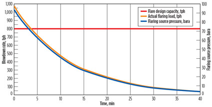
Fig. 1. Flaring load from major flaring source with single BDV. |
Flare system design basis. The flare system being studied has the following design basis:
- The flare design capacity is considered to be 800 tph to accommodate the flare system within the available plot battery limits and the acceptable radiation and dispersion levels, and to limit the flare height.
- All flaring sources within a single fire zone are to be depressurized simultaneously. The depressurization load will be calculated by considering the depressuring of each flaring source from its design pressure, to 6.9 barg in 30 min for the slug catcher, and to 15 min for all other sources. A 30-min depressurization time for the slug catcher was derived based on the vessel wall temperature vs. stress to rupture for selected material and thickness. For the sake of simplicity, it is assumed that no other flaring sources are located in a fire zone where the slug catcher is located.
- Other fire zones will be depressurized manually, in a staggered fashion, at defined time intervals or with a predefined automatic logic sequence. The time interval for the depressurization sequence of each fire zone will be established in such a way that the cumulative flaring load from one or multiple flaring sources will remain within the flare design capacity.
- Cumulative flaring loads from various flaring sources of other fire zones are assumed to be within the flare design capacity. To simplify, the study is limited to depressurization of the slug catcher. However, in a real design, this study must be extended to derive the cumulative load from all flaring sources in all fire zones.
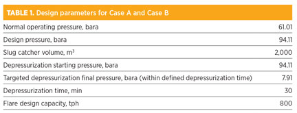
Case study: One vs. multiple valves. A case study was performed for a vessel-type slug catcher for two cases, one with a single BDV (Case A) and one with multiple BDVs with a staggered depressurization sequence (Case B). Common design parameters are considered for both cases, as shown in Table 1.
 |
Case A. The slug catcher and other flaring sources can be simulated using modern software programs. Depressurization can be performed using dynamic features to develop the following depressurization curves of flow, in terms of pressure vs. time.
From this information, it can be observed that, with consideration of a single BDV, the peak flaring load will be 1,080 tph, which is higher than the flare design capacity.
Case B. To limit the major source flaring load within the flare design capacity, multiple BDVs with a staggered depressurization sequence can be considered, as the flowrate through the orifice significantly decreases with time. The number of BDVs and the opening interval for each BDV shall be defined in such a way so that the peak cumulative blowdown loads remain within the flare design capacity.
The time delay between each step is calculated using the flow/time relationship for each depressurization valve, as per the simplified Eq. 1, which can provide reliable depressurization curves. The depressurization sequence model for the slug catcher can be built in a spreadsheet.
F = F0e−θt(1)
where the exponent coefficient factor θ can be derived from:
P = P0e−θt(2)
The numbers of BDVs and the depressurization sequence can be estimated using the multiple dynamic depressurizing utility that is available within a steady-state simulation software and spreadsheet.
However, it is recommended to model a complete flare system using dynamic simulation software to optimize the flare design accounting dynamics involved in each source operating parameters with time—i.e., volume, liquid levels, pressure, temperature, etc. It is also recommended to avoid the transfer of large numbers of data from simulation software to a steady-state flare model to estimate the back pressure and other parameters—i.e., Mach number, momentum criteria (ρV²), etc., for each depressurizing event for complete flare system network analysis.
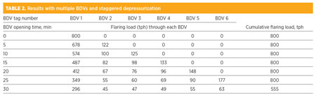 |
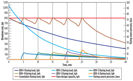
From Table 2 and Fig. 2, it can be concluded that, with multiple BDVs, it is possible to depressurize the slug catcher from design pressure to 6.9 barg in 30 min, with six numbers of BDVs in staggered fashion. Each BDV will open after five minutes (BDV opening time is assumed to be negligible), with the first BDV opening at zero time, or at the same time as depressurization is initiated.
 |
|
Fig. 2. Flaring load from major flaring source with multiple BDVs. |
Critical design considerations. For solenoid valves and uninterruptable power supply, the use of normally energized solenoid valves with 1oo1 or 1oo2 configurations is recommended. If normally deenergized valves are used, then the solenoid valve configuration will be 1oo2; i.e., if one solenoid valve fails to energize or fails to open on energization, then the depressurizing valves will still open.
Solenoid valves should be controlled from the IPS. The uninterruptable power supply backup of IPS should be sized for 30 min or longer, depending on the overall depressurization cycle time. As per API 521, credit can be given for sufficiently reliable backup power supplies (e.g., uninterruptable power supply).
However, the inherent safety of the flare system will be questionable if the design fails to demonstrate that reliable backup power will be available on demand. There is a possibility of main power and uninterrupted power supply (UPS) failure. Digital output (DO) card failure is a remote event, but it cannot be neglected. Such an event could lead to overpressurization of the flare system and the failure of its components, since all normally energized and/or 1oo2 deenergized BDVs will open simultaneously.
Various parameters contribute to determining if the depressurization load must be reevaluated as relevant:
- Generally, the well pressure profile depicts numbers of operation years; however, this credit will be neglected, as an incident may happen during the early years of production.
- In the case of a blocked slug catcher outlet, pipeline packing could take a considerable amount of time (depending on pipeline volume) and could settle out at a considerably higher pressure—i.e., close to the slug catcher design pressure, excluding design margins.
However, if the slug catcher inlet emergency shutdown closure with a high safety integrity level-rated system could be set at a lower pressure setting (i.e., 70 barg), then the possible settle-out pressure in the case of a blocked slug catcher outlet could be approximately 75 barg. This trip logic will ensure that the slug catcher will never be operated at a higher pressure than 75 barg. - In the case of a power failure, all flaring sources will be anticipated to operate at normal operating pressure and not at the design pressure. However, as per the American Petroleum Institute (API), it may be preferable to consider pressure switch high/high as the depressurization starting pressure for all flaring sources, except compressors and slug catchers. For compressor settle-out conditions and for slug catcher trip packing, pressure shall be considered as described previously.
These concerns can be mitigated with the following design implementations:
- The redundancy of slug catcher staggered blowdown will be increased by the distribution of BDV inputs from two or more different DO cards, instead of one. The BDVs should be distributed in such a way so that failure of one card will not lead to overpressurization of the flare system due to possible flowthrough upon the available opening of associated BDVs of that particular card. Each group of BDVs shall be assigned to a different chassis and to different cards with different cable routing to eliminate common mode failures in the system. Risk shall be minimized as low as reasonably possible (ALARP).
- The redundancies of slug catcher staggered blowdown shall be increased by using dual-type BDVs. In this configuration, some BDVs will be retained as “normally energized” and remain “normally deenergized.” This configuration ensures that, on unexpected loss of UPS on demand, the simultaneous depressurization load will remain below the flare design capacity, and it will also remain functional during normal operation when the UPS will be available.
However, the total slug catcher inventory must be depressurized from 75 barg to 6.9 barg within 30 min in fire, as well as in the adiabatic depressurization case, for both of the aforementioned design implementations. If design mitigation fails to achieve the final pressure within the definite time, then the Case B study must be repeated to determine the number of BDVs and the correct blowdown sequence, until the desired depressurization sequence and the design implementation are achieved. - If deemed necessary, UPS for each fire zone/local equipment room can be considered.
Design checks before implementation. Several design checks must be carried out before the implementation of design mitigations:
- Ensure that the depressurization starting pressure of all flare sources are rightly studied and considered in the case of total power failure.
- Ensure that all flaring sources are considered while deriving the cumulative flaring load in case of a power failure—i.e., pressure control valves (PCVs) fail to open to flare. If required, the failure position of PCVs can be altered to the fail close position after a careful review considering all operational scenarios.
- Based on vendor confirmation, ensure that any compressors that cannot be kept in pressurized conditions for a long time are accounted for while deriving the peak flaring load at the start of the depressurization sequence.
- Consider dedicated air volume bottles for each BDV. The design requirements of air volume bottles shall be as per applicable codes—i.e., DEP 32.45.10.10-Gen Feb 2011, which states that “Upon instrument air supply failure, the secure instrument air (SIA) system shall maintain sufficient pressure in the buffer vessel to allow for at least three valve strokes, based on an initial pressure in the SIA vessel equal to the minimum instrument air header (IAH) pressure.” The SIA vessel will be supplied from the IAH via a filter. Two non-return valves shall be installed to prevent backflow from the SIA system in the case of loss of IAH pressure. The non-return valves will be of the ball or poppet type, mounted in the vertical line with an upward flow direction, and marked as Class 1 on the process engineering flow diagram. Bleeding devices, such as regulators, should not be used downstream of the non-return valves. A low-pressure alarm will be provided to indicate low air pressure in the SIA, set at the minimum pressure that is required for three valve strokes.
- Ensure that the maximum back pressure, Mach number, ρV², etc., in the advanced simulation model are within the flare header design limits.
- Ensure that the flare knockout drum will withstand pressure, temperature and flaring load without compromising separation particle size and liquid holdup time requirements corresponding to the total power failure case.
- Ensure that the radiation and dispersion calculations at the peak flowrate are within a safe radiation limit at the plant fence and at the sterile radius.
- Ensure that all other relevant design criteria based on project-applicable philosophies are adhered to.
Takeaway. It is always recommended to design a flare system that is simple and inherently safe, accounting for all possible and applicable relief scenarios as defined in various codes and guidelines. However, sometimes limitations can be applied at various stages of design to optimize overall design and/or flare system design. Such limitations may demand a tailor-made design approach that meets the project-specific requirement without jeopardizing the safety of the facility.
Carefully considering multiple BDVs with staggered depressurization sequences, conducting what-if analyses of each component’s failure, having an adequate failure mitigation plan in place, and performing complete design checks can limit the cumulative flaring load from flaring sources within the flare design capacity. GP
NOMENCLATURE
t=Time from start of depressurization, min
F=Flow through orifice (depressurization load at time, t), tph
F0=Initial flowrate through orifice (peak depressurization load), tph
ρ=Fluid density, kg/m3
P=Final pressure (internal pressure at time, t = t), bara
P0=Initial pressure (internal pressure at time, t = 0), bara
V=Velocity, meters/sec
θ=Exponent coefficient factor depending on orifice size, min–1
 |
Ajay Vyas is a senior process engineer at Abu Dhabi Gas Industries Ltd. (GASCO) in the UAE. He has more than 14 years of experience in process design for oil and gas refineries and petrochemical facilities. Mr. Vyas holds a BS degree in chemical engineering from Nirma Institute of Technology in Ahmedabad, India, as well as an MBA degree from the University of Atlanta in Dubai, UAE.


Comments