
Retool heat exchanger design for different operating scenarios
U. Vengateson, National Petrochemical Co., Yanbu, Saudi Arabia
For many applications in the process industries, process fluid (either gas or liquid) is heated by steam to maintain the desired process outlet temperature. Generally, the process fluid is heated in the tube side of a shell-and-tube heat exchanger by the steam flow in the shell side.
The steam condensate from the exchanger is collected in a condensate drum and discharged to the steam recovery section by either a level control valve (LCV) or a steam trap. The flowrate and pressure of steam, along with the exposed heat-transfer area in the exchanger, play important roles in maintaining the desired process outlet temperature.
Design guidelines for heat exchanger systems are given here, along with working principles of the systems for various operating scenarios, such as startup, normal and turndown cases. A detailed case study is also provided.
Introduction. In Fig. 1, the process fluid (gas) is heated in the tube side, and the steam passes through the shell side of the exchanger. Steam flow, and its pressure to the heat exchanger, is indirectly controlled by a temperature control valve (TCV).
 |
|
Fig. 1. Schematic of steam-heated exchanger system. |
Assume that the steam is saturated at the exchanger inlet and that the steam condensate flows to the condensate drum through a long, vertical leg. The condensate drum is maintained at pressure, P3, by steam flow to the drum from the steam header through the pressure control valve (PCV). The steam header pressure is P1 bara, and the condensate drum is maintained at P3 bara for all cases. A process requirement is that the exchanger must be operated for fixed process outlet temperature (Tout) for different operating flowrates in the tube side.
The main objective of the design is to answer the following questions:
- How much vertical leg height is required?
- What flow and pressure drop must be specified for the data sheet for control valves TCV, PCV and LCV?
The working principle of the system and the design strategy to meet various operating scenarios, such as startup, normal and turndown, are described below.
System hydraulics. Assume that the heat exchanger is elevated at a height, L, from condensate drum liquid level, and the condensate drum pressure is maintained at P3. Since steam and condensate flows go from the exchanger to the condensate drum, they must satisfy Eq. 1:
P3 = P2 + PL – ΔPex – ΔPL(1)
where:
P3=Pressure in condensate drum
P2=Pressure at heat exchanger inlet
PL=Pressure due to static head
ΔPex=Pressure drop in exchanger due to flow
ΔPL=Friction loss in pipe due to flow.
The next question to be answered is: How much pressure can be maintained in the exchanger inlet for maximum and minimum steam flow through the exchanger? For the maximum steam flow case, pressure cannot be maintained at higher than the condensate drum pressure, P3. The pressure can be estimated by assuming that steam condensate is removed from the exchanger as soon as it is formed. In this situation, condensate backs up in the vertical leg, only to compensate for the frictional loss in the exchanger and pipe, as shown in Eq. 2:
P2 = P3 and PL = ΔPex + ΔPL(2)
In the minimum steam flow case, condensate may be backed up to the exchanger outlet, at maximum, as shown in Eq. 3:
P2 = P3 – PL + ΔPex + ΔPL(3)
If the exchanger and pipe are oversized to keep the frictional loss at a minimum, then there will be no condensate backup for the maximum steam flow case, and there may be maximum full condensate seal leg for the minimum steam flow case.
Eqs. 4 and 5 portray the extreme cases that are limited:
For maximum steam flow: P2 = P3(4)
For minimum steam flow: P2 = P3 – PL(5)
Flow through TCV. The function of the TCV is to provide the necessary steam flow to maintain the desired process outlet temperature. The rate of steam flow is not controlled directly by the TCV; rather, the steam flowrate to the exchanger is controlled by the rate of steam condensation, which is controlled by the TCV.
The rate of steam condensation depends on the heat-transfer capacity, UA, the driving force, ΔT, and the latent heat of steam, λ, at the condensing temperature, as shown in Eq. 6:
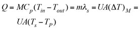 (6)
(6)
Steam flow to the exchanger is limited by its rate of condensation, m, as shown in Eq. 7:
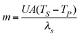 (7)
(7)
Assume that U and λ are constant for a wide range of process flow conditions and steam pressures. For the fixed inlet and outlet temperatures of the process fluid, the higher the saturation temperature of steam, the higher is the rate of condensation. The steam temperature in the exchanger corresponds to the saturation pressure of steam in the exchanger. By opening the control valve wider, the steam pressure in the exchanger can be increased.
Design flow. For the design flow case, more steam is needed to flow. To admit more steam flow, the rate of steam condensation should also be increased. This increase can be accomplished by indirectly raising the saturation temperature of steam in the exchanger. The TCV can be opened wider, and the pressure maximum can be increased to the same level as that of the condensate drum pressure, since the drum is maintained at a desired setpoint of P3.
 |
The limiting factor for the setpoint of the condensate drum pressure is the steam header pressure. Therefore, the highest possible steam condensation temperature is saturation temperature, T3, which corresponds to P3. The maximum possible steam flow to the exchanger can be calculated from Eq. 8; however, the steam requirement for the design flow will be less than this value, since the saturation temperature will be less than T3, as shown in Table 1.
 (8)
(8)
Normal flow. The process flow intended to operate during the normal case is the normal flow. The steam required for the normal case is less than that required for the maximum flow case; therefore, the steam saturation pressure must be reduced below the condensate drum pressure.
By raising the liquid level in the condensate leg, the necessary pressure can be obtained in the steam side of the exchanger. If the pressure is Pn, then the required steam flow can be calculated using Eq. 9:
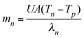 (9)
(9)
Turndown case. During turndown, less heat duty is needed due to reduced process flow. The rate of steam condensation should be decreased to meet the turndown heat duty. Accordingly, saturation temperature (and, therefore, saturation pressure) must be lowered. The steam pressure in the exchanger can be decreased by raising the condensate maximum to the exchanger. A taller condensate leg results in a lower steam pressure, allowing the steam condensation rate to be slowed.
Until this point, the entire surface area of the exchanger was assumed to be exposed for heat transfer—i.e., A is constant. If the heat duty is to be further reduced for any reason, this can be achieved by raising the condensate to the exchanger shell side, so that a portion of the tube bundle is submerged in the condensate and not exposed to heat transfer. This will reduce the exposed heat-transfer area, A, in addition to decreasing the saturation temperature.
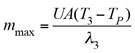
However, the submergence of a tube bundle will sometimes cause process fluctuations, so the additional reduction of heat duty by decreasing A will not be considered. The minimum steam flow to the exchanger when the condensate leg is fully sealed is calculated from Eq. 10:
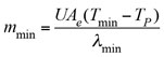 (10)
(10)
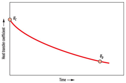
Turndown case for clean exchanger. During fresh startup, or after each time the exchanger is cleaned, the value of the heat-transfer coefficient is high (U = Uc), due to the lack of fouling. Over the course of time, however, the exchanger becomes fouled on both the shell side and the tube side, and the overall heat-transfer coefficient is reduced due to service, as shown in Fig. 2.
 |
|
Fig. 2. Variation of heat-transfer coefficient with operating time. |
At some point in time, the exchanger becomes excessively fouled and is unable to meet the process duty requirement. When the overall heat transfer coefficient reaches UD, the exchanger is recommended for cleaning. Therefore, the service period of the exchanger is from UC to UD. The value of UC and UD for the design case can be obtained from the thermal data sheet for the exchanger.
In comparing turndown cases for the clean exchanger and the dirty exchanger, the heat duty, Q, is the same for both cases because the process flow and its terminal temperatures are maintained. Heat-transfer area, A, is also the same for both cases. However, the value of U is different, as shown in Eqs. 11 and 12:
QC = UCA (ΔT)mc (11)
QD = UDA (ΔT)md (12)
When the exchanger is clean, U is greater (U = UC) than the exchanger at the end of the service period (U = UD). To achieve the same heat duty, the clean exchanger should have a smaller mean temperature difference (MTD) and, therefore, a lower steam temperature and pressure than the dirty exchanger. Steam pressure must be evaluated for the turndown clean exchanger case, and the condensate leg should have sufficient height to attain this limiting pressure.
Flow through PCV. The control valve in the line is meant to allow steam flow to the condensate drum to maintain the desired set pressure, P3.
Design flow case for dirty exchanger. In the design flow case, the exchanger and the condensate drum are more or less maintained at the same pressure; steam breakthrough occurs in the condensate leg, from the exchanger to the condensate drum. As a result, there is little to no steam flow through the PCV to the condensate drum.
Turndown case. As discussed previously, during minimum flow, the maximum possible condensate backup in the leg is to the bottom of the exchanger (Point 4 in Fig. 1). At this location, the condensate is at saturation temperature, which corresponds to the exchanger outlet pressure.
When this condensate flows downward, its pressure increases due to gravity, and there is no change in temperature as long as the pipe is well insulated. At any point in the condensate leg, the condensate temperature is less than the saturation temperature corresponding to its local pressure. This means that the condensate is being subcooled on its way to the condensate drum.
In the drum, the steam is in equilibrium with the liquid. When the subcooled condensate from the condensate leg mixes with the saturated steam/condensate in the drum, the steam in the condensate drum tends to condense to establish a new equilibrium at reduced temperature, and the steam pressure starts to decrease.
To restore the pressure in the drum, the control valve PCV must open to maintain the desired set pressure. Based on mass and energy balance calculations shown in Eqs. 13 and 14, the steam flow through the PCV can be determined from Eq. 15:
m6 = m3 + m4 (13)
m6H6 = m3H3 + m4H4 + m4gL (14)
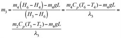 (15)
(15)
where:
λ3=The latent heat of steam at the condensate drum set pressure, P3
L=The height of the condensate creep up the vertical leg from the liquid surface in the condensate drum.
Saturation temperature, T3, corresponds to the condensate drum set pressure, and saturation temperature, T2, corresponds to the steam-condensing pressure in the exchanger.
LCV fully open case. Steam condensate from the condensate drum is discharged through the LCV to the condensate collection header and reaches the condensate flash drum as part of the steam recovery system. The purpose of the LCV is to maintain a liquid level in the condensate drum and discharge only the condensate to the flash drum, so that no steam breaks through the condensate drum.
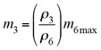
If the LCV is fully open, then it will discharge more condensate than steam condensed in the exchanger. It will reduce the liquid level in the drum, allowing the steam to expand in the drum, reducing its pressure. To restore the pressure, steam must be admitted to the PCV, to compensate the rate of volume change in the drum. The steam flowrate through the PCV is given in Eq. 16:
F3 = F6max – F2 (16)
In Eq. 16, F6max is the volumetric flow based on the control valve size, Cv, which is fixed. F2 is the steam condensed (volumetric flow) in the exchanger at the time of the LCV failure. The lower the F2, the more F3 is required; during the turndown/clean exchanger case, F2 is lower and F3 must be evaluated:
F3 = F6max (17)
However, for practical reasons, steam flow through the PCV is evaluated assuming F2 = 0, using Eqs. 17 and 18:
 (18)
(18)
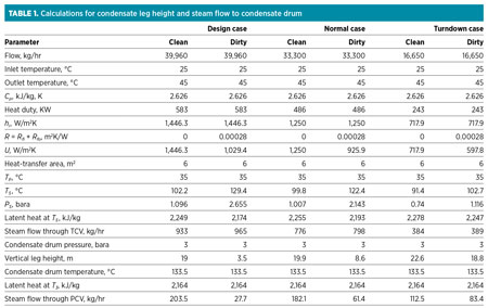
Case study. Natural gas is heated in the tube side of the exchanger from 25°C to 45°C by steam flow in the shell side. The flow requirement and heat duty for different cases, along with the selected heat exchanger area, are shown in Table 1.
Steam flow, and its pressure to the heat exchanger, are controlled by the TCV. Assume that the steam is saturated at the exchanger inlet and the steam condensate flows to the condensate drum through a long, vertical leg. The steam header pressure, P1, is at 4 bara, and the condensate drum is maintained at a pressure of 3 bara for all cases.
As a part of the calculation procedure, the overall heat transfer coefficient, U, must be evaluated for all cases. Steam condensation temperature and pressure correspond to each case. The rigorous value of U can be calculated from proprietary software for all cases, or it can be estimated with plausible simplifying assumptions.
In an overview of U estimation for different process flowrates, the overall heat-transfer coefficient is calculated using Eq. 19:
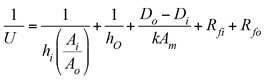 (19)
(19)
For the sake of simplicity, the tube material can be assumed to have good thermal conductivity (k → ∞). Tube material thickness is very small, so metal resistance is negligible, and Ai ≈ Ao. The calculation can then be revised as shown in Eq. 20:
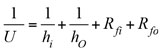 (20)
(20)
Fouling resistance. When the exchanger is put into service during initial startup or after a thorough cleaning operation, the fouling layer is not present—i.e., fouling resistances are zero, and the overall heat-transfer coefficient is given by Eq. 21. This coefficient is normally referred to as Uc (the clean heat transfer coefficient):
 (21)
(21)
During the course of plant operations, the internal and external surfaces of the tubes are gradually deposited by the dirty materials, arising from tube-side and shell-side fluids, respectively. These deposits provide resistance to heat transfer, called fouling resistance; Rfi is the tube-side fouling resistance and Rfo is the shell-side fouling resistance. These values are dynamic; they depend on time, fluid velocity, temperature and other factors.
Initially, for a clean exchanger, these values are set at zero and increase with time. After reaching a certain value (i.e., Rfi or Rfo, after two or three years of operation), the exchanger is unable to perform the heat duty, and the exchanger must be cleaned. Fouling resistance for the service fluids can be obtained from the literature,1, 2 or it will sometimes be specified by the client through project design basis, which takes into account the time span for successive cleanings.
For a running exchanger, fouling resistance can be monitored based on plant data, using Eq. 22:
 (22)
(22)
Here, dirty exchanger refers to the exchanger at the end of service—i.e., Ut = UD; Rt = R.
Film-transfer coefficient. The tube-side film-transfer coefficient for a single phase can be estimated from the Dittus Boelter equation. Once the hi is calculated for the design case, it could be scaled for other cases, normal and turndown, using Eq. 23:1
hi = M0.8 (23)
The shell-side film-transfer coefficient is a bit difficult to estimate due to the complicated flow path in the shell side. However, in this case, the tube side is hydrocarbon and the shell side is condensing steam. The condensing film-transfer coefficient for steam (shell side) is usually between 5,500 W/m2K and 17,000 W/m2K,2 which is much higher than the light hydrocarbon single-phase film-transfer coefficient. The controlling resistance for heat transfer in this case lies in the combined effect of tube-side film-transfer coefficient and fouling, as shown in Eqs. 24 and 25:
 (24)
(24)
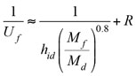 (25)
(25)
Eq. 25 offers a prediction of the overall heat-transfer coefficient, Uf, for any tube-side flow, Mf, of the steam-heated exchanger, when the tube-side design flow, Md, and the corresponding film-transfer coefficient, hid, are known.
Steam condensation temperature and pressure. Once the overall heat-transfer coefficient is estimated for all cases, saturation temperature of the steam, Ts, in the exchanger for each case can be calculated from Eq. 26:
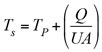 (26)
(26)
Saturation pressure of steam corresponds to saturation temperature, which is obtained from the steam table or can be roughly estimated from Eq. 27:
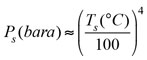 (27)
(27)
The rate of condensation of steam in the exchanger—i.e. steam flow through the TCV—is calculated from Eq. 7. The latent heat of steam at the saturation temperature is obtained from the steam table, or it can be roughly estimated from Eq. 28:
λs = (kJ / kg) = –3.0709 Ts (°C) + 2553.3(28)
Height of condensate leg. Once the steam saturation pressure in the exchanger, P2, is estimated, the height of condensate leg, L, is calculated from the hydrostatic law of pressure, as shown in Eq. 29. Here, P4 is approximately equal to P2 since steam condensation pressure drop is negligible:
 (29)
(29)
The calculated condensate leg height for all cases is listed in Table 1.
Specification of CVs. To purchase the control valve, it is the process engineer’s responsibility to specify the pressure drop across the valve with flow requirements (minimum, normal, maximum). Specifying the extreme cases (minimum, maximum) is important since controllability of the full operation lies between these two extremes.
In this case study, the maximum flow for TCV is the design flow. Pressure drop corresponds to the dirty-exchanger case and must be considered for this flow, since it requires lower pressure drop and, therefore, greater opening of the valve. The required minimum flow through the TCV is turndown flow, and pressure drop corresponds to the clean-exchanger case and must be considered for this flow, since it needs more pressure drop and less opening of the valve.
The pressure drop is the difference between inlet pressure and outlet pressure for the CV. The inlet pressure of the CV is the steam header pressure, and the outlet pressure is the steam-condensing pressure in the exchanger. Steam flow through the TCV, and the corresponding pressure drop, are evaluated for different cases and presented in Table 2.
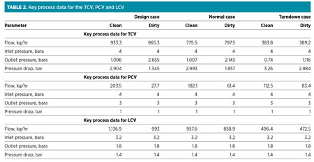 |
Maximum steam flow through the PCV occurs during the design-flow clean-exchanger case since more steam flows through the exchanger with lower condensation temperature. It is possible that the turndown clean-exchanger case may demand more steam flow through the PCV due to too-low condensation temperature, compared to saturation temperature in the condensate drum. Steam flow through the PCV is evaluated for different cases and presented in Table 2. For the LCV fully open case, the flow through PCV (as calculated from Eq. 18) is 2.65 kg/hr, considering a flowrate of 1,500 kg/hr when the LCV is fully open.
The flow through the LCV is the sum of the steam condensed in the exchanger and the steam flow through the PCV. The inlet pressure of the LCV is calculated by adding static head (2 m) with condensate drum pressure, and the friction loss in the pipe is neglected.
The outlet pressure is the backpressure from the low-pressure (LP) condensate receiver vessel in the steam condensate system. If the downstream line of the LCV is rising upward to connect to the common condensate collector line, then the static pressure must be added to the LP condensate receiver vessel pressure. In this case, a 5-m rise is considered, and the receiver vessel pressure is maintained at 0.3 barg.
Design guidelines for line and vessel sizing. The line and vessel are sized based on recommended velocity. Sizing guidelines are given below:
- Maximum allowable velocity in steam pipe (m/sec) = 5Di (in.), but not more than 30 m/sec
- To maintain the condensate in liquid form, the maximum velocity of condensate in the pipe is in the range of 0.3 m/sec–0.6 m/sec
- To obtain the condensate drum diameter calculation, set the velocity of condensate in the drum in the range of 1.5 cm/sec–2 cm/sec
- The length of the condensate drum is approximately fixed to 2.5–4 times the diameter, and the desired holdup time in the vessel is 3–5 min
- A sizing chart3 can be used to select the LCV downstream line size, since the condensate is flashing.
Takeaway. Steam-heated heat exchangers are widely used in process industries. Understanding the steam and condensate flow in the system for various operating scenarios is essential for sound design. Highlights of the presented case study with simplified theoretical background are as follows:
- As shown in Table 1, the required condensate leg height is more applicable to the turndown/clean-exchanger case, as compared to other cases. During the detailed engineering design phase, the elevation must be checked with the plot plan and 3D piping model. If enough elevation is not available, it is possible to submerge part of the tube bundle in the condensate to reduce the effective area and meet the heat duty, but it may lead to unstable operation.
- Steam flow through the PCV is generally higher for the design-flow clean-exchanger case. Sometimes the turndown clean-exchanger case may demand more steam flow through the PCV. In this case, the maximum flow through the PCV is for the design-flow clean-exchanger case.
- Higher steam pressure is required for the design-flow/dirty-exchanger case. Steam condensate drum set pressure should be equal, or it can be slightly higher than the steam pressure in the exchanger. The steam condensate drum set pressure is judged based on steam header pressure and backpressure from the LP condensate receiver vessel, which collects condensate from various sources.
- General guidelines for line and vessel sizing are provided; however, the project design basis must be followed. GP
Nomenclature
A Heat transfer area, m2
CP Specific heat, kJ/kg K
F Steam flowrate, m3/hr
H Enthalpy, kJ/kg
hi Tube-side film transfer coefficient, W/m2K
ho Shell-side film transfer coefficient, W/m2K
k Thermal conductivity of tube-side material, W/m2K
L Height of condensate leg, m
M Tube-side mass flow rate, kg/hr
Md Design tube-side mass flowrate, kg/hr
m Steam flowrate, kg/hr
P Pressure, bara
PL Pressure drop due to static head in condensate leg, bar
Q Heat duty, KW
Rfi Tube-side fouling coefficient, W/m2K
Rfo Shell-side fouling coefficient, W/m2K
R Sum of Rfi and Rfo, W/m2K
Tin Tube-side inlet temperature, °C
Tout Tube-side outlet temperature, °C
TP Average of process inlet and process outlet temperatures, °C
Ts Saturation temperature of steam, °C
U Overall heat transfer coefficient, W/m2K
UC Overall heat transfer coefficient at clean condition, W/m2K
UD Overall heat transfer coefficient at dirty condition, W/m2K
Uf Overall heat transfer coefficient for any process mass flowrate, W/m2K
v Velocity of process fluid in a tube, m/sec
ΔPex Exchanger pressure drop on shell side, bar
ΔPL Frictional pressure drop due to condensate flow from exchanger to drum, bar
ΔTm Log mean temperature difference, °C
ΔTmc Log mean temperature difference at clean condition, °C
ΔTmd Log mean temperature difference at dirty condition, °C
ρ Density of tube-side fluid, kg/m3
λ Latent heat of steam, kJ/kg
µ Viscosity of tube-side fluid, kg/m/sec
min Corresponds to minimum flow
n Corresponds to normal flow
t Time
Literature cited
1Smith, R., Chemical Process Design and Integration, John Wiley & Sons, Hoboken, New Jersey, 2005.
2Cao, E., Heat Transfer in Process Engineering, McGraw-Hill, New York,
New York, 2009.
3“Sizing condensate return lines,” Spirax Sarco, 2015.
 |
Uthirapathi Vengateson works as a senior process design engineer at National Petrochemical Co. in Yanbu, Saudi Arabia. For more than a decade, he has been involved in the design, precommissioning and commissioning of chemical and petrochemical plants. Prior to this, he worked at Lurgi India Co. Ltd. in India. Dr. Vengateson received a BTech degree in chemical engineering from Madras University and an MTech degree in petroleum refining and petrochemicals from Anna University. He earned his PhD in chemical engineering from the Indian Institute of Technology in Delhi in 2010. He can be reached at drvengateson@gmail.com.


Comments