
The ‘seven deadly sins’ of filtration and separation systems
D. Engel, Nexo Solutions, The Woodlands, Texas; and M. Sheilan, Sulphur Experts, Calgary, Canada
Separation systems play a fundamental role in gas processing, both for reliability and as enabling devices for enhanced throughput and process stability. In many cases, these systems are the only and/or last line of defense to protect the plant from unwanted and detrimental contaminants. As plants are required to process gas with more contaminants (such as certain shale gas feeds), these devices are increasingly being required to perform under progressively difficult conditions.
As the authors evaluate, troubleshoot and improve many of these systems at a number of plants worldwide, they have identified many different failure modes in these systems, with various degrees of severity. These modes can range from incorrect design to poor choice of physical location, to errors in instrumentation and erroneous or nonperforming internals.
A number of these cases were combined and compiled into a list of the seven most common errors in filtration and separation systems used in gas processing operations. The effects of not having correct contamination control in gas processing have profound impacts on plants and manifest as solvent contamination and degradation, foaming, fouling, low reliability, low efficiency, increased maintenance and undesirable environmental emissions.
All of these effects lead to higher operational costs and/or the inability to meet sweetening or dehydration specifications. Each “deadly sin” is analyzed and presented with actual plant cases. Additionally, each case is analyzed for its effects, consequences or ramifications and, in some cases, for how the problem was successfully corrected.
Processing and contamination control. For almost any gas processing plant, contamination is a reality that can cause numerous associated problems and, if not solved properly, will become a chronic problem. Some of the problems caused by contamination include foaming, fouling, corrosion, solvent degradation, deposition, undesired side reactions and downstream impacts (such as in sulfur recovery units, flares and in treated products).
These problems invariably cause capacity reductions, efficiency decay, inability to meet specifications, equipment failures, loss of solvent, high maintenance and operational costs, ultimately leading to undesired environmental emissions and the loss of profitability. Most, if not all, of these detrimental effects can be mitigated by using proper contamination control measures. These situations can be addressed by the use of chemical additives or mechanical separators. In this article, only mechanical separator solutions are discussed.
Mechanical separation in gas processing, as related to contamination control, is usually undertaken in two of the following areas of the process:
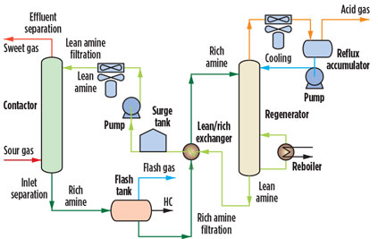
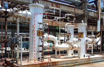
- Feed and effluent separation, referred to as contamination removal in feed streams and in effluent streams, such as sour gas or wet gas (feed) and treated/sweet gas or dry gas (effluent) (Fig. 1)
- Unit internal separation, which relates to contamination removal within the unit, such as amine solvents, glycol solvents and other gas processing solvents.
 |
|
Fig. 1. Amine unit diagram showing the streams subjected to feed and effluent |
Both of the preceding categories demand different separation approaches and, in many cases, different mechanical separation systems. Feed and effluent separations are typically associated with gas streams, with the exception of LPG and NGL. Unit internal separation is associated with liquid streams (solvents) in the unit. In both cases, the predominant mechanisms for contaminant separation are as follows:
- Filtration: For suspended solids in a liquid or gas stream
- Coalescence: For liquids in a gas stream or emulsifiers in a liquid stream
- Adsorption: For dissolved, predominantly organic components in a gas or liquid stream.
Feed and effluent separation. Proper feed gas or liquid contamination control, prior to processing, is essential to maintain plant stability, plant performance and low operational costs. Proper control is often achieved when there is thorough understanding of virtually all inlet feed contaminants in the gas stream. The information is taken into consideration when determining what separation process and system should be used. Inlet contamination in gas processing can vary drastically and depends on a number of factors:
- Geographical location and geological formation
- Gas exploration and production operations and equipment types
- Chemical additive use (type and dosage)
- Contaminant types and concentrations.
Aside from heavy hydrocarbons and acid gases [hydrogen sulfide (H2S) and carbon dioxide (CO2)], feed streams can contain other sulfur-bearing species [i.e., carbonyl sulfide (COS), carbon disulfide (CS2), mercaptans (RSH), etc.] and many other contaminants. The most common contaminants in gas feeds are asphaltenes, waxes, water, oxygen, mercury, sulfur (elemental), ammonia (NH3), methanol, salts, compressor lubrication oils, chemical additives, iron sulfides/oxides, silica and sand. These contaminants do not include any heat-stable salt precursors typically associated with refineries.
Feed gas and effluent gas (treated gas) contamination control is often conducted through the use of knockout drums equipped with a demister section, using a mesh pad or a vane pack. Some plants use horizontal filter separators with a vane, or cyclonic elements or stages.
None of these systems are entirely adequate for an effective inlet contaminant removal from sour gas feeds. These systems are typically designed for either bulk liquids removal or large aerosol droplet size removal, as opposed to the fine sub-micron-size liquids found in many gas streams. In addition, none of these devices is specifically designed for solids separation, which is usually accomplished with a wet scrubber or a particle filter.
With the exception of cyclonic systems and some filter separators that can remove certain solid particles and some liquid aerosols, most liquid contaminants enter the gas processing units untouched. In essence, demisters are just as effective as slug catchers.
Unfortunately, the most difficult and challenging contaminants in any gas stream are small aerosols. These aerosols are finely divided liquid particles with diameters ranging from a few hundred microns (µ) to less than 0.1 µ. Separation of these liquid contaminants is done using microfiber sub-micron gas-liquid coalescers (MSCs). These MSCs should be capable of removing, on average, > 99.97% of all aerosols with diameters between 0.1 µ and 1 µ (and also larger). In practice, this represents the majority of the liquid aerosol contamination in a gas stream. These devices should be protected with a suitable particle filter separator (equipped with the correct separation media) to extend the online life of the coalescer and to minimize operational costs, since the replacement filter elements for particle separation are much less expensive than coalescing elements.
Correctly designed sub-micron coalescer vessels have two stages: the bottom section designed to remove bulk liquids, and an upper “high-efficiency” stage for aerosol removal. In certain situations, the bottom section can be fitted with a mesh pad or vane pack, or it may be designed to have cyclonic action. The gas leaves the bottom chamber, flowing into the second stage immediately above via the interior of the coalescing elements. It is then directed across the microfiber coalescing media from the internal core to the exterior surface. The fine aerosols are intercepted, coalesced and finally drained from the elements by gravity. Like the lower stage, the upper stage has a liquid removal system comprising a level control and drain valves.
Unit internal separation. This process is related to contamination removal within the unit, dealing with recirculating solutions, such as amine solvents, glycol solvents and other gas processing solvents. These solutions are generally particle filters for removing suspended matter, coalescers to promote liquids contamination separation (typically hydrocarbons, both free and emulsified) and adsorption beds, such as activated carbon, to remove dissolved components.
Other adsorption systems are molecular sieve beds, alumina/silica beds and salt beds. All three common separation processes are in place in gas processing operations. These processes include filtration, coalescence and adsorption. Other less common processes are available, although they have limited applications.
One such technology is heat-stable salts removal in amine units, which can be achieved with ion exchange, electrodialysis or vacuum distillation. However, the use of these technologies is limited to amine units containing these contaminants and where feed control is deficient or not feasible (typically, refinery amines in connection with fluidized catalytic cracking, visbreaker and coker units).
Seven deadly sins of separation devices. All of the previously discussed concepts are fairly generic. Certain gas processing facilities may still operate well with high levels of contamination, while others will be disrupted at minimal contamination ingress. Each unit is almost a separate case in terms of contamination control and what measures are required for efficient contamination removal.
Throughout the authors’ involvement in evaluating gas processing units and mitigating deficient or negative situations, it became apparent that a large number of these facilities did not have the appropriate contamination control devices. In many cases, the devices were either deficient or nonexistent.
While troubleshooting these gas processing facilities, it became evident that there was a set of general failure categories covering the majority of the root-cause problems in filtration and separation methods. These failure categories, or modes, were later considered to be the seven largest problems found in separation devices in gas processing facilities.
Sin No. 1: Unsuitable technology for the application. This issue is related to the use of devices that are not capable of properly functioning for the application in which they are used. This is generally found in cases where poor understanding of the application leads to incorrect equipment selection. In some cases, perceived capital cost savings also lead to incorrect equipment selection.
An example of incorrect equipment selection can be found in the use of automatic filters with metal-based filter media in amine units. Although they seem promising, these devices do not perform adequately in amine units, mainly because of the contamination types found in the streams.
The highly fouling amine streams (rich and lean) with strongly adherent and sometimes gel-like solids cause back-washable or any other self-cleaning mechanical systems to perform well below their expected efficiency. The contaminants cannot be removed to any significant extent. The use of backwash liquid volumes can be large, and the cleaning frequency can be high. The efficiency of the metal filter element seldom returns to values near its original state. In addition, these solids, in combination with hydrocarbon contamination, are perhaps one of the most challenging mixtures to separate.
A secondary effect is that the new backwash stream with high solids content must be treated somewhere. If this is not taken into consideration prior to equipment selection, then it becomes a problem rather than a solution. This situation also applies to pre-coat systems with the use of diatomaceous earth as a filter aid.
Although these devices are important applications for the process industry, they can be very difficult to maintain, and waste generation and high amine consumption can be a problem. For amine units and other gas processing systems, solid waste residues coupled with solvent losses are highly problematic. If H2S is present, the waste is also toxic and must be disposed of as hazardous material. Some of these systems can be expensive and large in size, with considerable capital cost and maintenance expenses.
Finally, the use of cyclonic devices can, to some extent, assist in solids separation, provided the solids have the right particle size and density. These devices are more commonly used for bulk separation. The application of cyclonic devices is quite specific, and the operational windows are rather small; therefore, process variations are not well supported by these devices without changes in their configuration. However, the lack of moving parts and high-temperature operational capabilities make them attractive in many potential applications. The industry is full of such technology misapplication examples. Simple disposable filtration is still one of the best alternatives for the filtration of suspended solids in gas processing operations.
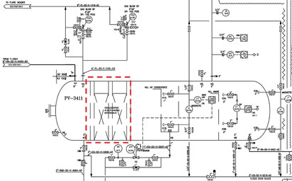
To illustrate a design misapplication, Fig. 2 shows a drawing of an amine unit flash tank in the UAE. This vessel was designed for only five minutes of residence time because it was equipped with internal mesh pads for hydrocarbon coalescing. (Note: These pads were not removable.) The concept of internal coalescing pads led to the idea that there was no need for the normally recommended 25 to 30 minutes of residence time in the flash tank. As a result, the tank was built significantly smaller in size than normally expected.
 |
|
Fig. 2. Amine flash tank drawing showing the internal metal-based coalescing |
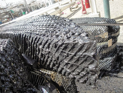
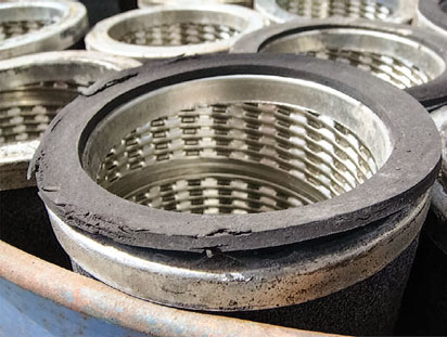
The basic concept might have been somewhat correct if coalescing was to be done on large liquid droplets in a non-fouling stream. However, given the high amount of heavy hydrocarbons (waxes and asphaltenes) in the feed stream to the unit, the designer should have recognized the potential for the amine solution to be severely fouled with solids. By installing the mesh pads in spite of the potential for contamination of the rich amine, the worst-case scenario of rapidly fouled internal coalescer pads was realized (Fig. 3), leading the plant to temporarily suspend operations at a significant loss of revenue.
 |
|
Fig. 3. Plugged coalescing pads removed from the inside of an undersized |
The pads have since been removed, but the short residence time has become a problem, since the flash drum can only remove flashable or free hydrocarbon. No emulsified hydrocarbons can be removed to any extent.
Sin No. 2: Incorrect compatibility (thermal, chemical, mechanical). Several aspects must be understood in materials compatibility. In general terms, the effects on media and associated materials (such as metal parts, screens, epoxy adhesives and end caps) are complex. These can include chemical degradation of the media (media erosion and distortion), media disassembly (media fiber release), media solubility (loss of media material), media modification (incorporating contaminants in the fiber) and media leaching (residues being released from the media material).
Thermal compatibility is related to the melting point (or the softening point) of the material. High temperatures generally lead to deformation of the material matrix and likely enhancement of chemical degradation. Mechanical compatibility is directly related to the tensile strength of the material. In other words, how strong is the material at the actual process conditions?
Chemical and thermal incompatibilities can also lead to rapid mechanical degradation and vice versa. An example of such a situation is the use of polyester filter media in any process that contains amines (either as a solvent or as a contaminant). Polyester undergoes chemical reaction with amine solutions, essentially causing the fiber to fail and eventually rupture.
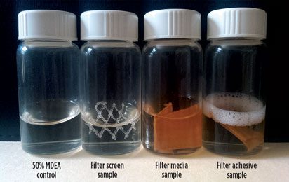
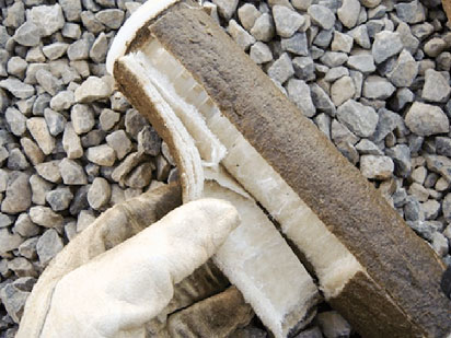
To illustrate incompatibility, Fig. 4 shows foam formation and stabilization in an amine solvent caused by the materials in a filter element (epoxy seam). An amine unit in the US experienced foaming in the absorber. After extensive investigation, the filter element was evaluated for chemical compatibility. A properly conducted soak test of all materials in the filter element indicated that the adhesive used to connect the media was causing foam stabilization. A change to compatible filter elements eliminated the foaming.
 |
|
Fig. 4. Samples soaked in lean MDEA at room temperature for 48 hours. Foam |
Sin No. 3: Deficient vessel design. As seen in many real cases of poor contamination control, the leading cause is often a defective vessel design. Defective design can occur in many forms:
- Undersized vessels (especially coalescers)
- Unbalanced placement of internals causing preferential flow
- Baffles causing incorrect flow geometries or liquids chattering
- Incorrect placement of inlet, outlet or instrument nozzles
- Erroneous vent or drain location
- Undersized thickness of plate support for internals
- Lack of vents, drains or pressure reliefs.
In some cases, certain vessels can be modified, upgraded or improved. However, for vessels that are undersized, there is no practical solution. Filters will have exponentially high operational costs. Coalescer vessels will have considerable liquids carryover, and other separation systems will simply lack separation efficiency, resulting in excessively high operational costs.
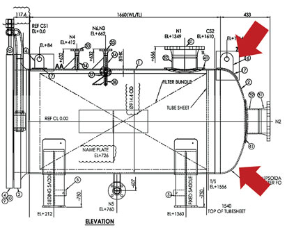
Fig. 5 shows a vessel drawing for a particle filter in a rich amine stream in the UAE. A vapor vent (N4) and a liquid drain (N5) on the left (i.e., dirty) side of the tubesheet are present. Neither a vapor vent nor a liquid drain is present on the clean side of the tubesheet. At the very least, a vent should exist in the clean side of the filter. The lack of a vent produces a pocket of gas that is usually high in H2S and CO2 concentrations.
 |
|
Fig. 5. Rich amine particle filter design showing the location where a clean side |
This pocket cannot be eliminated, as there is no place for the gas to escape. An internal plate separating the clean and dirty sides prevents the gas from venting. The resulting formation of a gas-liquid interface leads to a high potential for metallurgical failure in the near future. Vessel modification is required to include a vent and a drain on the clean filtration side.
Sin No. 4: Inappropriate sealing surfaces. Often overlooked are sealing surfaces, which make a fundamental difference in the actual performance of the elements compared to the expected performance. The sealing surfaces are present at the interface where the internal element, responsible for actual contamination separation, meets the vessel. These parts play the critical role of ensuring that the fluid is properly routed into the separation media, effectively producing a seal between the contaminant-laden stream and the clean stream.
These parts are usually gaskets or O-rings produced from so-called “elastomers” (polymers with flexible elasticity). Each elastomer has its own compatibility, as indicated previously. Some sealing surfaces actually rely on the contact between the media itself with metal parts at the vessel (called seat cups). These are poor in performance and prone to bypass. Flat gaskets are also deficient, since they must be attached to the element itself by using an adhesive. These gaskets often fail to offer a proper seal, causing contaminant bypass.
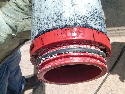
Fig. 6 shows filter elements with flat gaskets that have been degraded. The edge of the material is eroded, and, in parts, sections of the elastomer material are missing. On the elements in the background, the gasket is actually missing. Modification of the vessel to utilize filter elements with improved and chemically compatible O-ring seals eliminated the bypass. O-ring seals in filter elements or coalescing elements do not use adhesive materials.
 |
|
Fig. 6. Coalescer elements with sealing surface materials that have been |
Sin No. 5: Wrong internals and media. This general area relates to incorrect filter element design and encompasses incorrect media selection. Elements with poor design and a less-than-optimum media surface area will have a reduced contamination capture capacity and a low online life, therefore requiring more frequent maintenance.
Poor design also generates higher waste volumes and results in higher operational costs. However, excess media surface area in a filter element will lead to reduced contamination capture capacity as a phenomenon called media “blinding” takes place. This occurs when parts of the media experience ineffective exposure to the fluid stream. Media efficiency selection is also an area where a number of failures occur. Failures tend to happen because of poor understanding of the tradeoffs in any process separation, in terms of separation cost vs. the downstream effects of contamination penetration. It is always critical to understand why a given contaminant is required to be removed and what the operational expectations of the filter are at the location where it will be installed.
Fig. 7 shows a filter at a European plant that was designed with the expectation to operate as a depth filter. The expectation was for the filter to accumulate contaminants, not only at the media surface, but also at the inner media layers. It can be observed that only the outer media layer is actually being used, leaving the inner sections contaminant-free. A new media array, with different materials and efficiencies, produces an element capable of accumulating contaminants in all inner layers of the filter.
 |
|
Fig. 7. Filter element with incorrect media. The internal layers of the media are |
Sin No. 6: Lack of, or incorrect, maintenance procedures. It is surprising how many filters and other separation systems go without proper maintenance. Many systems operate for years with no differential pressure increase; then, when workers open the vessel, they discover no internals.
Several other vessels are found to be using non-original, low-cost internals to save money. Typically, these internals are the culprit for many processing upsets, as they lack the robustness to handle variable contaminant concentrations. Proper maintenance of any separation system must start with a thorough internal inspection of the vessel to detect any possible anomalies and/or damage. The sealing surfaces must be inspected so that they are clear of solid deposits, minimizing the possibility of deposit bypass. Periodic monitoring of internals replacement procedures is critical to ensure the correct accommodation of the internals into the vessel, leading to proper operation.
Fig. 8 shows the end cap of a coalescer element at a US plant with missing O-rings used for sealing. Maintenance workers manually removed the O-ring, indicating that this helped the element to fit. Also, a white residue was found at the base of the end cap. This residue is hardened material originating from the grease used to facilitate element accommodation into the vessel.
 |
|
Fig. 8. Filter element with one of its O-rings removed. The oil used to lubricate |
The grease material reacted with the hydrocarbons in the gas stream, forming a solid material and cementing the element into the vessel. Element removal caused internal support damage. The use of inert mineral oil led to a much smoother element installation with no incompatibility issue. All future installed elements had both O-ring gaskets to properly seal the element in the separator housing.
Sin No. 7: Instrumentation deficiencies. Another often disregarded area is instrumentation. Some systems are never equipped with instrumentation, while others have incorrect instrumentation. For example, level controls must properly consider the density of the interface fluid that is supposed to be measured (liquid-liquid or gas-liquid).
The location of instrumentation is also important, since some units in cold locations have no protection. They often freeze and provide incorrect readings. Proper monitoring of differential pressures is important since it is the only way some vessels can “communicate” with the operations staff. Filters have differential pressure devices that must be verified for accuracy. Coalescer vessels are much more complex. They use differential pressure gauges, level controls and dump valves. All of these components are required for effective liquids removal. If any of these components become damaged, or are missing or defective, then liquid carryover will likely occur.
Fig. 9 shows a gas conditioning skid (pre-filter and liquids coalescer) with missing instrumentation in Latin America. Level controls are not connected to any automatic dump valve to remove liquids from the vessel interior. The level control was not wired to the control room. Liquids removal was done periodically and manually. Often, this leads to the entire coalescer vessel being filled with liquids, causing slugs of liquids to enter the downstream units (usually an amine absorber), generating uncontrollable upsets and foaming because of high hydrocarbon ingression.
 |
|
Fig. 9. A gas coalescing skid showing the large coalescer vessel equipped with |
To avoid such a situation, a level control connected to a dump valve must be installed. This ensures that any liquid accumulation inside the vessel is always managed properly and that liquids removal from the vessel is performed correctly.
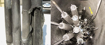
In a plant in Canada, an excessive pressure differential across the coalescer elements caused the elements to rupture (Fig. 10). Upon inspection of the vessel internals, damage to the support arm of one of the risers was also detected (yellow arrow). The high pressure differential was a result of excessive plugging of the outer coalescing layer by solids and salts, leading to excessive pressure drop in a matter of days. Operations did not catch the high pressure differential because the remote pressure transmitter was frozen. The transmitter is now insulated, allowing for constant readings in the control room.
 |
|
Fig. 10. Ruptured coalescing elements and damaged riser support arm caused |
Takeaway. Invariably, the vast majority of process upsets, lack of profitability and impacts on efficiency are related to contamination control. Additionally, perhaps one of the most important and fundamental factors in process control is proper contamination control. Plants that do not take contamination control seriously and rigorously often struggle with high operational costs and low systems reliability, followed by a number of other undesired technical, economical and environmental impacts.
In the authors’ experience, the seven areas discussed here comprise the bulk of the reasons as to why filtration and separation systems do not perform as expected, or why errors are encountered in their utilization. By focusing on the material covered previously, filtration costs will likely decrease, and operational expenses will be frequently lowered.
With proper contamination control leading to effective process control, units will perform better, with greater stability and capability for effectively enduring process imbalances. It is also critical to point out that, in the authors’ numerous worldwide trips for troubleshooting processing plants, it has been observed that any capital savings from low-cost filtration and separation equipment ultimately lead to exponentially higher processing costs, low equipment reliability, frequent unit upsets and loss in profitability.
Each processing unit has its own equilibrium point where the cost of contamination removal is acceptable, with tolerable residual contamination level breakthrough. This is where users, engineering firms, consultants and suppliers have the responsibility to be involved in finding such balance points, with the objective of supplying the right filtration and separation solution for each individual plant. GP
 |
David Engel has more than 20 years of industrial experience in a variety of areas. He is the inventor in 17 US invention patents and the author of a number of technical and scientific papers. Dr. Engel has also developed businesses and technologies for Pentair, General Electric, Sulphur Experts, Eastman Kodak and Eli Lilly. Recently, he specialized in advanced process systems and multicomponent separation methods for removing or mitigating contaminants in process streams. Dr. Engel is the cofounder of Sulphur Experts’ Filtration Division and the managing director of Nexo Solutions. He is a member of the editorial board of Elsevier Publishing, the board of directors of Genesis Biohealth and the board of directors of AFCOM. Dr. Engel holds a BS degree in industrial chemistry and a PhD in organic chemistry, and is Six Sigma certified.
 |
Michael Sheilan is a chemical engineer with 34 years of varied industry experience. He has been involved in all aspects of the natural gas processing industry, primarily in relation to the chemicals used to treat gas and the processes that use these chemicals. He has provided expert advice and consulting services in the areas of hydrate control, gas dehydration, gas and liquids sweetening, hydrocarbon recovery and sulfur plant operations. Most recently, he has focused on amine plant troubleshooting and plant optimization for the sour gas and oil refining industries. Mr. Sheilan is a regular speaker at the internationally recognized Sulphur Experts seminars, leading the amine sessions. In addition, he provides expert advice to clients and has performed onsite assessment and training for most of the major producers in the industry.


Comments