
Manage gas feedstock and NGL quality at treating plants
S. H. Al-Mudaibegh, Saudi Aramco, Dhahran, Saudi Arabia
Contamination of gas and NGL streams has been a chronic issue at Saudi Aramco facilities and at plants around the world. Major contaminants in process streams include corrosion products (black powder), water in gas and NGL streams, liquid HC in gas streams and glycol in product gas streams. The presence of these contaminants is mainly attributed to inefficient filtration/separation and process control and corrosion management.
To overcome operational issues caused by contaminants in sales gas and NGL, several measures are taken. These include pipeline scraping, installation of feed gas filters/separators, anti-foam injection, fresh solvent addition, and installation of conventional mechanical solution filters. However, in many systems, these methods are ineffective and do not represent the optimum solution.
A program to manage contamination issues in gas and NGL plants through online measurement of contaminants in process streams and evaluation of filtration/separation was initiated. This initiative had several objectives:
- Address contamination issues in major gas and NGL streams
- Qualify/quantify the gas and NGL contaminants in major streams at gas plants
- Use the study outcome to resolve chronic contamination issues by modifying existing systems, applying new filtration/separation technologies and developing best practices for new designs.
The expected benefits include enhanced process performance, improved equipment reliability and operating cost reduction through improved filtration and contaminants control.
The online test included major gas plants, NGL fractionation, gas/oil separation plants (GOSPs), locations on the master gas system (MGS) and locations at the end-user (consumer) inlet. Findings and results of the completed contaminant online measurement at these facilities are presented.
Contamination case study. Saudi Aramco gas plants process more than 16 Bscfd of both sweet and sour gas. The main products from these plants are sales gas (fuel gas), which is used mainly to generate power; C2; and NGL, which are used as feedstocks to many petrochemical industries.
Natural gas processing in gas plants involves different processes, such as gas treating, NGL recovery and dehydration. It also requires transportation through a huge network of plant and cross-country pipelines. The presence of contaminants, such as solids (e.g., black powder) and free water in HC streams, causes many operational issues:
- Equipment damage:
- Frequent failures of NGL pump seal systems
- Fouling and plugging of reboilers (fractionation plants)
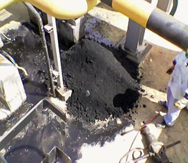
- Affect metering accuracy (Fig. 1)
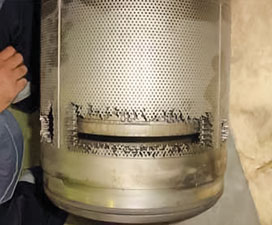
- Erosion of control valves (Fig. 2)
- Failure of customer-critical equipment/instrumentation.
- Process upsets:
- Off-spec product (high water in condensate/crude)
- Foaming in amine sweetening and glycol dehydration units
- Delay and reduced accuracy of pipeline in-line inspection.
- Safety and environmental issues, such as gas release (as seen at the Yanbu and Riyadh power plants).
 |
|
Fig. 1. Black powder accumulation on metering station. |
 |
|
Fig. 2. Erosion of a control valve at Berri Junction. |
Saudi Aramco experienced significant black powder formation in a sales gas pipeline network, which resulted in several upsets in customer plants downstream. The formation of black powder is attributed mainly to carryover of solids, with the sales gas from the plant and the formation of black powder in the pipeline due to water, oxygen (O2), and hydrogen sulfide (H2S)/carbon dioxide (CO2) presence at a certain level. In addition, equipment damage due to the solids present in NGL feed at fractionation facilities has been reported. As a result, many black powder filters were installed at critical locations to protect the end-user facility.
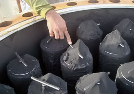
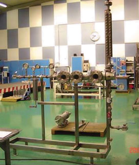
Saudi Aramco collaborated with a filtration company to perform online measurements of solid and liquid contaminants and assess filtration/separation equipment (Fig. 3) using a pilot liquid/gas and liquid/liquid (L/L) filter/separator skid. The field test provided the required data for quantifying and qualifying contamination, assessing filtration/separation efficiency at gas plants and identifying areas for enhancement.
 |
|
Fig. 3. Black powder on absolute filters on sales gas |
The online measurement test scope included major gas, NGL and condensate streams from gas plants and the pipeline network. It also included measurement of solid/water and liquid carryover, with quantification and qualification of solid and liquid contamination levels.
Methodology and testing. Equipment used during testing included:
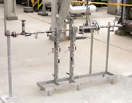
- Liquid/gas (L/G) coalescer skid (Fig. 4) with a proprietary coalescing element to separate liquid from gas
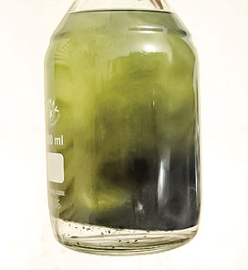
- L/L coalescer skid (Fig. 5) with a proprietary coalescing element to separate water from liquid HC
- Pre-filter with a proprietary filtering element to separate solid from liquid HC
- Gas sampling device plus a proprietary membrane to measure solids in gas and liquid.
 |
|
Fig. 4. L/G coalescer skid. |
 |
|
Fig. 5. L/L coalescer skid. |
In the gas stream test, the L/G coalescer skid was connected to the main stream lines, and the outlet was connected to the closest flare line. The test was commissioned by flowing a constant rate (approximately 0.5 MMscfd) of the gas and monitoring the liquid that accumulated in the bottom sump. The accumulated gas flow and liquid collected were recorded throughout the test. Several runs were performed to confirm measurements.
In the liquid stream test (Fig. 6), the L/L coalescer skid inlet was connected to the main stream line using 1-in. stainless steel tubing. The skid outlet was connected to the proper location using a 0.5-in. or 1-in. tube. The solid sampling kit was also connected to the L/L coalescer skid.
 |
|
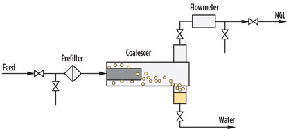
Fig. 6. Flow diagram of the coalescing process. |
The test began by flowing a slipstream of the NGL/condensate liquid through a prefilter to remove solids and protect the coalescer. The liquid was then introduced through the liquid coalesce, where water was separated from the HC and collected. The functioning principle of the L/L coalescence test unit is based on the separation of two immiscible liquids.
Analysis. For the solid content, the contamination level, or total suspended solids (TSS) content, was determined according to weight difference and gas/liquid volume processed through a 0.2-µm or 0.8-µm membrane.
Scanning electron microscopy, combined with energy-dispersive X-ray spectroscopy, was used to determine the size of the particles and the elemental composition of the collected contaminants. Optical microscopic observation was used for measurement of count and particle size distribution of contaminants collected on the membrane.
The separated liquid was analyzed visually, and density was measured for each phase. A water detector kit was used to measure free water in NGL/condensate for < 60 ppmv. Mass balance was used to detect > 60 ppmv content.
Results. The results obtained represent the system during the test. The test was repeated at some locations to reproduce the results, and it is being repeated at other locations. An extended-duration test and additional tools are required to improve the accuracy of the measurement.
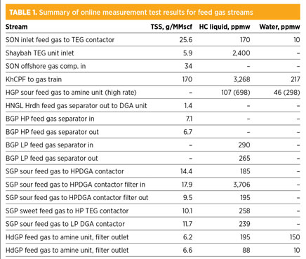
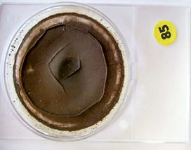
Table 1 summarizes the online measurement of solids and liquids carryover with feed gas streams at selected facilities. Fig. 7 and Fig. 8 show solids and liquids removed from sour feed gas at two different plants.
 |
|
Fig. 7. Solids removed at sour feed gas at ShGP. |
 |
|
Fig. 8. Liquids removed from sour feed gas at HdGP |
The average solid content in feed gas to all plants was 25 g/MMscf. Liquid hydrocarbon and water carryover to the plants were 600 ppmw and 190 ppmw on average, respectively. All feed gas filters/separators that were tested demonstrated very low efficiency in removing both solids and liquids. This was proven by conducting the measurement upstream and downstream from these separators. Note: The feed gas to the gas plants is from GOSPs, gas wells and sometimes from other gas plants, which causes a significant difference in contamination level—i.e., some streams were already processed through dewpoint control and dehydration before they were sent to gas plants for further processing.
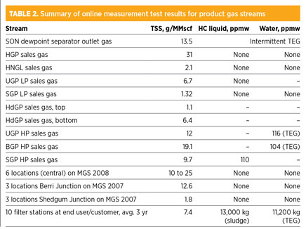
Table 2 summarizes the online test results for the fuel/sales gas streams. Solids were detected at the plants’ outlets, inside the pipeline (MGS) and at inlets to the end-user/customer facilities (Fig. 9 and Fig. 10).
 |
|
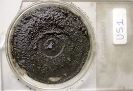
Fig. 9. Sludge collected upstream of the cyclone filter |
 |
|
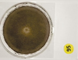
Fig. 10. Solids in HGP sales gas collected during |
The solid (black powder) content in product streams from plants ranged from 1 g/MMscf to 31 g/MMscf (average of 10 g/MMscfd). The average solid content across the pipeline was almost the same, at approximately 11 g/MMscf. Finally, the average solid content in the fuel/sales gas to the end-user/customer facility was approximately 6.3 g/MMscf.
The solid/black powder in fuel/sales gas to the end user/customer was calculated based on the amount collected in the last three years by the newly installed black powder filter stations, and this measurement represents more than 70% of fuel/sales gas delivered to the end user. In many cases, sludge was present, especially near Berri Junction, which receives fuel/sales gas from UGP, BGP and ShGP (all of which reported excessive TEG carryover) (Fig. 11 and Fig. 12).
 |
|
Fig. 11. Liquids (glycol) removed from BGP high- |
 |
|
Fig. 12. Wet solids removed at UGP high-pressure |
The presence of solids in all streams is a result of corrosion, erosion and, in some streams, sand from the field itself. Corrosion in the MGS pipelines is attributed to the presence of TEG/water carryover, H2S, CO2 and O2, in addition to the significant amount of black powder that is continuously carried out from gas plants to the pipeline. It also indicates the inefficient filtration equipment used at the different locations. Similarly, the liquid is attributed to inefficient separation and condition change through the pipeline—mainly temperature drop and/or pressure drop.
Significant amounts of liquid carryover were observed from the TEG dehydration units. The liquid was identified as TEG, mainly in locations with some liquid HC. This was verified at downstream filtration units installed on the MGS network at end-user battery limits. Historical measurement and review of the TEG operation at many plants showed that some units produce off-spec gas, where the water content is greater than 7 lb/MMscf.
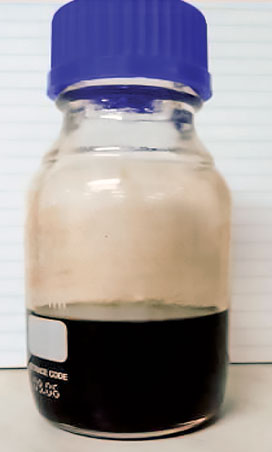
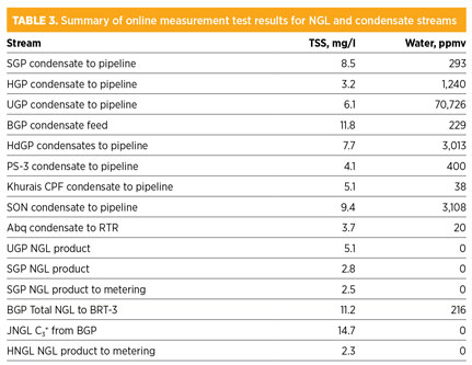
Table 3 summarizes the online measurement of solid and water carryover with NGL and condensate streams (Fig. 13 and Fig. 14). The average solid content in NGL and condensate streams after treatment in gas and NGL facilities was 4.3 mg/l and 7.6 mg/l, respectively. Except for BGP NGL, all NGL streams have no free water carryover, since these streams are coming from cryogenic plants as a result of NGL recovery, which involves molecular sieve dehydration. BGP NGL was a mixture of dry NGL and treated condensate, which already has free water and which has impacted the total water content of the stream. On the other hand, all condensate streams from the condensate stabilizer units have free water, which range between 38 ppmv and 3,100 ppmv.
 |
|
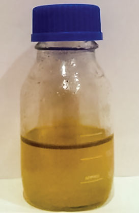
Fig. 13. UGP condensate to pipeline (clear layer of |
 |
|
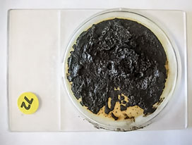
Fig. 14. Solids from Khurais NGL to pipeline. |
This value reached up to 71,000 ppmv for units that used a two-phase separator to remove free water. It can be concluded from these measurements that the condensate stabilizer operation does not guarantee removal of free water from condensate, although most of these units showed no free water in treated condensate based on process simulations.
Analyses of gas streams. The particle size distribution and nature of analyses conducted on the solids in feed and product gas streams are listed in Table 4. These analyses showed that 80% to 100% of the solids are less than 25 µm.
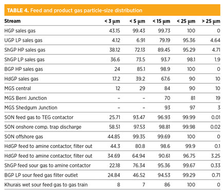
The slightly bigger size of solids on the sales gas network, compared to feed streams, could be attributed to agglomeration and/or further corrosion due to trace amounts of H2S, CO2 and water. Elemental analyses of solids in gas streams indicated the presence of iron (Fe), O2, sulfur (S), and traces of silicon (Si) and mercury (Hg). Silicon-based material and calcium carbonate (CaCO3) were significant in feed gas, especially from gas wells.
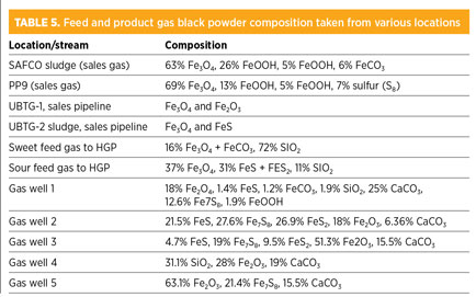
Based on compositional analysis, solids are mainly iron oxide (Fe2O3)-based corrosion products in fuel/sales gas, with some evidence of the presence of iron sulfide (FeS) in a few locations. Subsequently, FeS and Fe2O3 corrosion products are the main constituents in sour feed gas, in addition to significant amounts of CaCO3 and silicon oxide (SiO2) from gas wells (Table 5).
Analyses of NGL, condensate streams. Particle-size distribution for the NGL and condensate streams is shown in Table 6. Particle-size distribution and the nature of analyses conducted on the solids in NGL and condensate streams showed that more than 90% of the solids are less than 15 µm. Elemental analyses of solids in the NGL streams indicated the presence of Fe, C, S, O2, SiO2 and Ca.
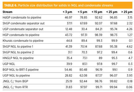
The analysis of solids in NGL and condensate streams using the X-ray diffraction technique showed that the majority of solid contaminants are identified as magnetite (Fe3O4), minor crystalline phases of S, siderite (Fe2CO3), iron carbonate (FeCO3). Mackinawite [(Fe,Ni)9S8] and FeS are also identified.
Actions taken. Mapping of gas and NGL contaminants provided essential data that helped supply better options to manage black powder in pipelines. Cyclone-type black powder filters were installed at critical locations, which eliminated carryover to end-user/customer facilities.
Areas of improvement within plants and upstream facilities have been identified. Gas dehydration units at several gas plants were upgraded to reduce black powder formation in the MGS by eliminating the potential high-moisture sources. Black powder filters were recommended at the battery limits of gas plants to prevent black powder and liquid carryover with fuel/sales gas to the MGS. Engineering documents to improve the design of filtration equipment were developed, along with control gas and NGL specifications.
Major findings and conclusions from this study include:
- Substantial amounts of black powder are present in the feed gas and in the produced fuel/sales gas and NGL streams in all tested facilities. This carryover contributes to the black powder presence in the MGS.
- Excessive water carryover with condensate occurs in pipelines at all facilities.
- Significant liquid (TEG and HC) carryover occurs with dry gas from TEG dehydration units.
- Significant liquid carryover to gas plants increases the potential for foaming and results in HC liquid losses to the dissolved gas analysis units. This is an indication of inefficient feed gas filter/separator equipment.
- The black powder is mainly an Fe2O3 corrosion product in sales gas, whereas FeS, in combination with Fe2O3, represents major compounds in sour feed gas streams from the GOSPs and gas wells. Few analyses showed FeS in fuel/sales gas, which is being verified by ongoing tests.
- Compositional analysis, along with elemental analysis, was used to analyze for the nature and composition of black powder.
- Approximately 80% to 90% of solid particles in gas and NGL/condensate streams are less than 25 µm in size, based on particle size distribution measurement.
- Feed gas filter/separator efficiency ranged from 10% to 90% for liquid removal and from 25% to 50% for solid removal.
- Absolute filters, with at least a 3-µm size, will be used for effective removal of solids from gas streams. For liquids with a minimum 5-µm size, filters will be used.
- The filter/separator design will be based on actual measurement for existing facilities. For new plants, the presence of black powder in feed streams will be considered in filtration/separation equipment. Data from similar feeds/products may be used for design basis.
- Condensate stabilizer operation is not reliable for free water removal. Dehydration of product streams or effective coalescing is needed to ensure removal of free water from condensate.
- For a large gas and NGL pipeline network, continuous monitoring and elimination of black powder sources (i.e., off-spec product) is critical to avoid process upsets and expensive investments.
- Mapping of gas and NGL contaminants provides essential data that leads to better options for managing black powder in pipelines. GP
ACKNOWLEDGMENTS
The author thanks Saudi Aramco facilities for providing the required support to successfully conduct the online measurements. Special thanks to Pall Corp. for technical discussions and for providing various test results and analysis data.
NOMENCLATURE
Abq Abqaiq gas plant
BGP Berri gas plant
CPF Central processing facility
HdGP Haradh gas plant
HGP Hawiyah gas plant
HNGL Hawiyah NGL recovery plant
JNGL Ju’aymah NGL fractionation plant
MGS Master gas system
PS-3 Pump station 3
RTR Ras Tanura refinery
ShGP Shedgum gas plant
TEG Triethylene glycol
TSS Total suspended solids
UGP Uthmaniyah gas plant
 |
Saud Al-Mudaibegh is a senior process engineer with Saudi Aramco’s gas processing unit, process and control systems department. He graduated from King Fahd University of Petroleum and Minerals in 1995 with BSc degree in chemical engineering. He has more than 18 years of experience in gas processing, and he has seven years of experience as a professional engineering development division instructor for gas treating and dehydration courses. Mr. Mudaibegh is also a technical committee member of SOGAT.


Comments