Gas plant diversity united by economics, flexibility and proven design
J. Lewis, WorleyParsons, London, UK
When examining technology options for new gas processing plants, it is important to consider how global gas plant diversity translates into design. It is also necessary to understand the available processing options and the complexity that is introduced by multiple-field processing.
Gas processing considerations
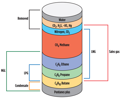
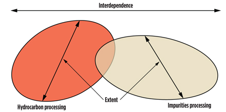
Prior to processing, natural gas comprises a mixture of components (Fig. 1). Processing adjusts the composition to allow for production of elements to saleable specifications, and this includes both impurities removal and hydrocarbon treatment. These two aspects (Fig. 2) are not independent, and an optimal process scheme will consider synergies between these aspects.
 |
|
Fig. 1. Natural gas composition. |
 |
|
Fig. 2. Processing interdependence. |
The transportation method used for gas—i.e., pipeline or LNG carrier—also impacts processing. For example, the liquefaction process requires removal of water, carbon dioxide (CO2) and C5+ hydrocarbons to typically less than 1 ppmv, 50 ppmv and 0.1 mol%, respectively. Pipeline gas and LNG specifications1 vary considerably around the globe, and LNG importers may need to spike the product with nitrogen (N2) to reduce calorific value to comply with local specifications.
Liquid products, namely mixed LPG or separate propane and butane, may also be required, and, while typical specifications are shown in the Gas Processors Suppliers Association’s Data Engineering Book,2 these are by no means universal.
Propane recovery is an often discussed aspect of gas plant design. Recovery could be minimized to that required for dewpoint and/or calorific value specification, or increased to levels in excess of 95%, where the price for propane exceeds that which can by obtained on calorific value alone. However, with increased propane recovery comes increased plant complexity and cost.
Non-hydrocarbon impurities include water, mercury, CO2, hydrogen sulfide (H2S) and other sulfur species, including mercaptans. As with hydrocarbon processing, removal levels are impacted by the gas market.
H2S is typically removed to < 4 ppmv, regardless of end use for sales gas; however, even at that level, further treatment of an LPG or propane stream may be needed to meet the corrosivity specification—i.e., “copper strip.”
With increased interest in sour gas processing, mercaptan removal features greatly in plant design. However, the key aspect is reservoir fluid analysis, both in terms of the quantity and the mercaptan species distribution. In fact, mercaptan removal can govern the entire gas-side configuration of a processing train,3 and it is a significant example of the interdependence between hydrocarbon processing and impurities removal.
Key thermodynamic aspects
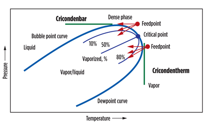
Fundamental to the processing of hydrocarbons in gas processing is a solid understanding of the phase envelope (Fig. 3), as well as the production and management of cold temperatures, which are key aspects. Cold temperatures can be achieved in three ways:
- Isobaric—at constant pressure (i.e., with external refrigeration)
- Isenthalpic—at constant enthalpy (i.e., with Joule-Thomson expansion)
- Isentropic—in practice, an approach to constant entropy (i.e., with turboexpansion).
 |
|
Fig. 3. Phase envelope. |
The intent of all three pathways is to cut into the phase envelope to achieve condensation and, therefore, subsequent removal of a liquid phase. The operating point within the phase envelope is determined within the design process, and it will be where the condensation contours are widely spaced. This allows for a predictable degree of condensation, which can be managed in operation. Working near the critical point is to be avoided; where small differences in temperature give large percentage differences in condensation, latent heats approach zero, and K-factors approach unity.
Accurate characterization of the feed gas is essential, as small differences in heavy-end components can result in significant differences in cricondenbar and cricondentherm. If this characterization is wrong, it can result in the presence of liquids in gas streams that are intended to be purely gaseous.
Gas processing options
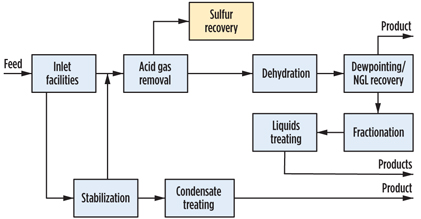
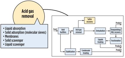
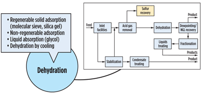
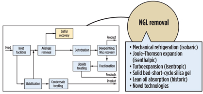
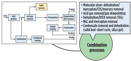
It is convenient to break a gas processing plant into discrete processing blocks (Fig. 4) and treat them with a certain degree of independence. Following this approach, acid gas removal, dehydration and NGL recovery options are summarized in Figs. 5, 6 and 7. Some functionality can also be combined (Fig. 8), but even this does not completely show the criticality of impurities and hydrocarbon processing interdependence, which lead to a holistic approach.
 |
|
Fig. 4. Typical gas plant process flow. |
 |
|
Fig. 5. Acid gas removal process. |
 |
|
Fig. 6. Gas dehydration process. |
 |
|
Fig. 7. NGL recovery process. |
 |
|
Fig. 8. Combination processes. |
An example of this complexity is found in sour gas processing, where, in addition to H2S and CO2, significant mercaptan presence has been analyzed in well testing. Such feed gases are becoming increasingly common in the Middle East. Acid gas components that are typically removed by amine in the acid gas removal unit (AGRU) are routed to a sulfur recovery unit (SRU), but a key aspect is the ratio of H2S to CO2 to the SRU—and, therefore, CO2 slip in the AGRU. This scenario requires the use of an H2S-selective amine that is typically MDEA-based. Increased complexity arrives with how to remove mercaptans; three approaches can be used:
- In the AGRU with a hybrid solvent (i.e., chemical and physical combined solvent)
- Combined with dehydration in a molecular sieve process, with additional treatment on the molecular sieve regeneration gas
- From NGL condensed in the NGL recovery unit, using a caustic-based process.
The advantages and disadvantages to these options are beyond the scope of this article; however, with increased interest in tight emissions specifications and high sulfur recovery requirements, any process scheme that adversely impacts the SRU requires close attention.
Once a design is implemented and a plant is in operation, it may have to accommodate a variety of challenges:
- Declining reservoir pressure
- Gradual souring
- Variable composition
- New product markets
- New reservoir fluids.
Some of these challenges are seen in the Central Area Transmission System (CATS) pipeline and processing facility in the UK. The pipeline system was commissioned in 1993 to carry gas from the Everest and Lomond fields in the UK sector of the North Sea. At that time, the CATS terminal included only reception facilities; gas was processed in an adjacent facility.
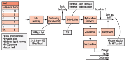
Two processing trains were later built, commencing operations in 1997 and 1998, to process gas from the Armada gas field in the central North Sea. Since then, however, multiple fields have been tied into the system via subsea tees in the pipeline. No CO2 removal facilities were required, and the plant was designed as a dewpoint plant, with minimum liquids recovery. The terminal now processes gas from a multitude of fields; those plant constraints are managed in operation. Had the plant been designed for today’s feed gases, the process configuration likely would not have been the same as that designed in the 1990s.
In conclusion, it can be stated that gas plants are different because:
- They have different feed and product slates
- They process gas at the condition in which it arrives
- Feed and product slates change over time
- Arrival conditions change over time.
In response to these scenarios, plant modifications are common.
Gas plant examples
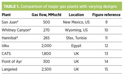
Several gas plants demonstrate some of the aforementioned attributes. The plants considered are listed in Table 1, and their simplified flow schemes are shown in Figs. 9–15. They were built over a period in excess of 30 years, so some degree of caution must be exercised regarding technology development. The quantitative data presented should be considered as indicative of the primary purpose to provide background to the different processes used.
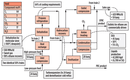
San Juan (Fig. 9) is a sweet gas plant in New Mexico, US, designed with the premise to achieve a very high degree of ethane recovery and nearly 100% propane recovery. This is not to say that the ethane and propane content of the feed gas is particularly high. Flexibility is provided in the design to also reject ethane into the sales gas stream, should economics dictate. As CO2 tends to follow ethane in process flow, an amine unit is required to remove CO2 from the NGL stream in the ethane-recovery scenario.
 |
|
Fig. 9. Process scheme for San Juan gas plant in New Mexico. |
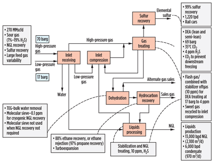
Whitney Canyon (Fig. 10) is a complex sour gas plant in Wyoming, US, that processes gas from four formations at different depths, with an H2S content ranging from 1 vol% to 19 vol%, and so requires sulfur recovery. As with San Juan, a high degree of NGL recovery is possible, and, alternatively, the plant can be operated in ethane-rejection mode. Dehydration is accomplished using triethylene glycol (TEG) contacting for bulk water removal, with molecular sieves used for secondary removal to below 0.1 ppmv of water required for the prevention of hydrates for NGL recovery operations. The NGL stream requires further sweetening, and a separate stabilized condensate stream is also produced. A sulfur-recovery requirement of 99% was specified in the original design, although it should be noted that this is considerably lower than “state-of-the-art” levels achievable.
 |
|
Fig. 10. Process scheme for Whitney Canyon gas plant in Wyoming. |
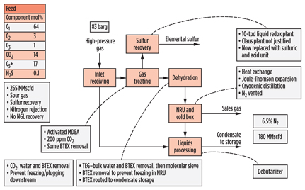
The Hannibal (Fig. 11) gas plant in Tunisia processes high-pressure gas from the offshore Miskar gas field to produce sales gas to meet hydrocarbon and water dewpoint specifications. The feed gas is high in both CO2 and N2, and so both are removed. CO2 (together with H2S) is removed in an amine unit prior to dehydration using both TEG and molecular sieves, as with Whitney Canyon. Both the amine and TEG also remove sufficient benzene, toluene, ethylbenzene and xylene, so as not to result in freezing in the downstream N2-rejection unit.
 |
|
Fig. 11. Process scheme for Hannibal gas plant in Tunisia. |
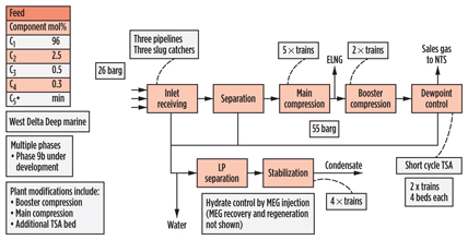
The Idku (Fig. 12) gas plant in Egypt, like CATS, processes gas from multiple offshore gas fields, but it is essentially a 50-well-plus subsea development, brought online in multiple phases, with first production achieved in 2003. Key developments since then have been the addition of two phases of compression, addition of a third feed pipeline, and the expansion of the temperature-swing adsorption system. The feed gas is very lean, and processing is limited to hydrocarbon and water dewpoint control using short-cycle temperature-swing adsorption, as well as condensate stabilization.
 |
|
Fig. 12. Process scheme for Idku gas plant in Egypt. |
The CATS plant (Fig. 13) in the UK receives dense-phase gas from offshore and treats it to a transmission sales gas specification. NGL removal is limited to that required for dewpoint control, and separate propane, butane and stabilized condensate streams are exported. No CO2 removal facilities are required, and H2S removal is accomplished using mixed metal oxide, in what is among the largest applications of that technology. Even with the formation of water from the reaction in the metal oxide beds, the low pipeline entry specification water content of around 20 ppmv results in no hydrate issues upstream of dehydration, and the high-pressure and low-temperature nature of the feed gas, combined with the relatively warm conditions for NGL removal, allows for dehydration to be achieved using TEG contacting.
 |
|
Fig. 13. Process scheme for CATS gas plant in the UK. |
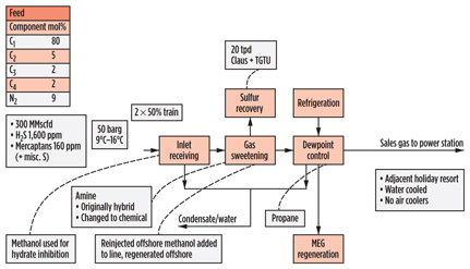
The Point of Ayr (Fig. 14) plant in the UK processes gas for transmission directly to a power station, and so its treated gas specification is governed by the power station requirements. CO2 and H2S are removed in an amine unit, which was originally designed for a hybrid solvent, as the need for mercaptan removal was initially identified.
 |
|
Fig. 14. Process scheme for Point of Ayr gas plant in the UK. |
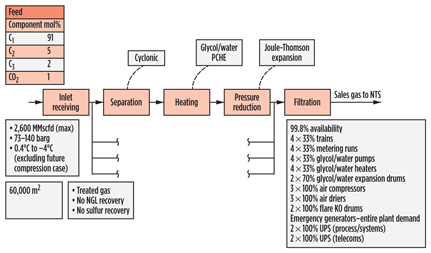
The Langeled reception facility (Fig. 15) in the UK receives fully treated gas; therefore, it does not perform any gas processing operations. However, gas reception, conditioning and metering provide particular challenges, as does the high availability requirement of 99.8%. Examples of how this was achieved are included in Fig. 15.
 |
|
Fig. 15. Process scheme for Langeled gas plant in the UK. |
Langeled is not a unique plant in terms of design intent; it is similar to terminals in Zeebrugge, Belgium; Dornum, Germany; and Dunkirk, France.
Project drivers and decision criteria
Regardless of processing means, gas monetization is driven by commercial arrangements. Developers seek minimum capital expenditure prior to first production, and they will maintain a schedule after the final investment decision to minimize their financial exposure. They will seek to maximize hydrocarbons recovery over field life and require maximum flexibility around evolving data. There will be a balance between maximum ramp-up and the production plateau, and future development will need to be accommodated.
In terms of design features, proven conventional technology will be preferred where it meets the design intent, safely. In summary, decision criteria for gas plant design and technology selection encompass capital expenditures, operational expenditures, inherently safe design considerations, flexibility and operability. GP
Literature cited
1Weeks, D., “GCV, WI, ICF or SI,” GPA Europe Conference, September 2009.
2Gas Processors Suppliers Association, GPSA Engineering Data Book, 13th Ed., 2012.
3Armstrong, L. and P. Roberts, “Challenges for processing oil and gas in Kazakhstan,” GPA Europe Conference, Sept. 2005.
4Kidnay, A. J., W. R. Parrish and D. G. McCartney, Fundamentals of Natural Gas Processing, 2nd Ed., CRC Press, Boca Raton, Florida, 2011.
 |
Jon Lewis is the global director for gas processing within WorleyParsons, with responsibilities spanning consultancy, project delivery, client support and business development. He has extensive conceptual and detailed engineering experience, and he has held various roles associated with gas processing terminals, offshore platforms and refineries in his 20-year career with the company. Mr. Lewis is based in WorleyParsons’ London office, where he is also director of process technology. He graduated with a master’s degree in advanced chemical engineering from the University of Manchester in the UK in 1980. A chartered engineer, Mr. Lewis has published several articles and has presented at international conferences.


Comments