
Simplify BOG recondenser design and operation—Part 2
S. P. B. Lemmers, Vopak LNG Holding BV, Rotterdam, The Netherlands
An LNG receiving and regasification terminal connects the intermittent process of LNG carrier unloading and/or loading with the mostly continuous process of LNG vaporization and gas transmission into a sendout pipeline system.
In addition to these LNG carrier operations, truck/train loading operations can take place simultaneously. During all operational modes of the LNG terminal, boil-off gas (BOG) is produced, which requires processing to avoid flaring or venting (under normal operating conditions) and to minimize the environmental impact of the facility.
Part 1 of this article discussed optimal designs for BOG recondensers used in LNG terminals. Here, operational aspects of BOG recondensers, based on the designs selected, are examined.
For the two BOG recondenser designs commonly used in the industry, there are several operational and process control elements to consider with respect to pressure and level control.
Annular space type
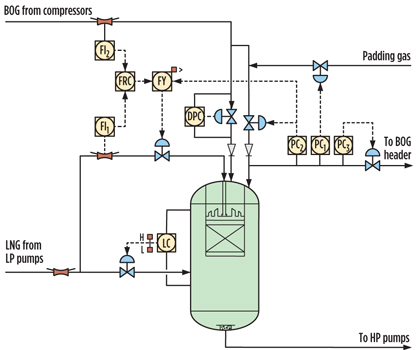
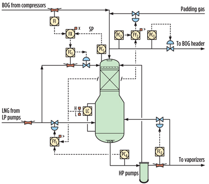
In Fig. 1, an annular space type of BOG recondenser is shown. This type is used in many LNG terminals, both older and newer. There are a number of advantages and disadvantages to this design.
 |
|
Fig. 1. Operation of an annular space BOG recondenser. |
The LNG and BOG enter the packed section. This type of BOG recondenser works by adjusting the amount of packed-section area available for condensing, by means of partial flooding of the packed bed. To achieve partial flooding while ensuring a constant level and net positive section head (NPSH) for the high-pressure (HP) pumps, a physical separation between the two packed sections and the annular space is required.
The level and pressure in the annular section are kept constant. The level and pressure in the packed section can be distinct from those in the annular section. Both the pressure and level in the packed section self-adjust in response to varying BOG/LNG ratios.
At high BOG/LNG ratios, the liquid level in the packed-bed section decreases automatically, through pushing of liquid to the annular space, as the pressure in this section increases. This process exposes more of the packed bed, increasing the heat transfer/condensation area to create equilibrium conditions—commonly referred to as the “auto-regulating” effect.
Likewise, a lower BOG/LNG ratio tends to reduce pressure in the packed section, which then results in a level increase in the packed section. In other words, this type of recondenser tends to adjust itself. Both the level and pressure in the two sections are different.
Pressure control. For stable operation of the BOG recondenser, the BOG compressor discharge pressure and annulus pressure must be controlled. Also, the annulus level and the BOG recondenser outlet temperature must be guarded to ensure sufficient NPSH for the HP pumps. The following examples of pressure control have been proven in the industry.
Example 1. The BOG compressors compress the BOG into the BOG recondenser. The BOG entering at the top of the BOG recondenser is condensed by contacting the BOG with subcooled LNG from the discharge of the low-pressure (LP) pumps over a packed bed in the BOG recondenser.
The pressure (and, therefore, the level) in the packed bed of the BOG recondenser varies with the ratio of LNG vs. supplied BOG. When the BOG/LNG ratio increases, the pressure in the packed section will rise, and the level in this section (which differs from the level in the annular section, as does the pressure) will decrease. This results in an increase of the available area for recondensation, thereby establishing a new equilibrium where all incoming BOG is fully recondensed.
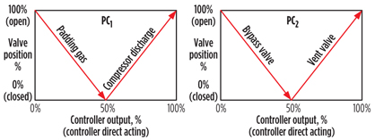
The discharge pressure of the BOG compressors is controlled via pressure controller PC1, and the pressure in the annulus is controlled via pressure controller PC2:
- PC1 is a split-range controller that maintains the pressure in the discharge of the BOG compressors via the control valve, which regulates the flow of BOG to the packed-bed section. If the BOG compressors’ discharge pressure becomes too low to guarantee sufficient NPSHrequired for the HP pumps, then PC1 will introduce padding gas from the HP natural gas system or fuel gas system.
- PC2 is a split-range controller that maintains the pressure in the annulus of the BOG recondenser. Even in the annular space, there will be some recondensation of BOG into the LNG at the interface. Therefore, to maintain pressure, some BOG must be fed into the annular space. On the other hand, ambient heat in-leak generates BOG, counteracting the above process. There is a need for split-range pressure control (i.e., bringing in BOG or venting to the BOG compressor suction head, as required). When the pressure rises, this controller will first close the control valve on the incoming BOG that bypasses the packed bed. Then, when the pressure rises further, PC2 will open the control valve to the LP BOG head upstream of the BOG compressors.
The control characteristics of both pressure controllers are depicted in Fig. 2.
 |
|
Fig. 2. Pressure control characteristics. |
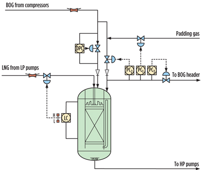
Example 2. To maintain both the correct pressure control (Fig. 3) of the annulus pressure and the NPSHrequired for the HP pumps, transmitters connected to the annular space provide an input to three pressure controllers to deal with low (PC1), medium (PC2) and high (PC3) pressure conditions:
- Under normal conditions, the pressure in the annulus will be maintained by gas from the BOG compressors by means of the PC2 pressure controller, which controls BOG flow into the annular space.
- If there is less BOG available, then the pressure in the annulus will tend to fall, and the pressure controller will introduce padding gas. Under normal conditions, the padding gas control valve will be closed.
- If the pressure in the annulus becomes too high, then the PC3 pressure controller will allow BOG to pass through the vent to the LP BOG head upstream of the BOG compressors. Similar to the padding gas control valve, this control valve will be closed under normal conditions.
- A differential pressure control valve will be provided in the line from the BOG compressors downstream of the split to the recondenser annulus and center section, to maintain positive BOG pressure upstream of the BOG recondenser.
 |
|
Fig. 3. BOG recondenser pressure control. |
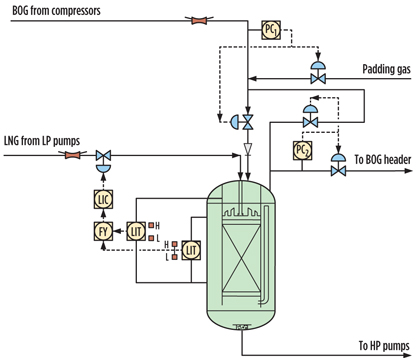
Level and total volume control. To ensure constant HP pump conditions, the LNG level in the annular space of the BOG recondenser is controlled via manipulating the LNG inlet valve to the packed-bed section of the BOG recondenser. The level controller must be tuned so that moderate fluctuations in the BOG recondenser level are allowed to prevent unacceptable disturbances to the LP pump operation. The control valve should have a high turndown ratio and high resolution.
As discussed previously, the level in the packed-bed section is not directly regulated; it will vary as a result of the BOG/LNG ratio. The higher the BOG/LNG injection ratio, the less contacting area is required for recondensation, and the higher the level will reach. When there is less contacting area, the pressure will rise and the level will decrease due to the increased pressure.
Conversely, when the BOG/LNG ratio is high, the pressure in the packed section will rise and the level will drop. This results in an increase of the available area for recondensation; the pressure will fall, and the level will rise again.
A practical result of this floating packed-section level is the following inverse-response phenomenon. If the BOG/LNG ratio increases, then the level in the packed bed will decrease, and the level in the annulus will initially increase because the pressure in the central section increases (pushing LNG from the packed section into the annular space), which forces the level controller (LC) to close the LNG inlet valve. This reduces the level in the packed-bed section even further.
To avoid this inverse response of the level control system, an LNG total volume control, based on both the level in the packed section and the level in the annulus, has been developed and implemented. This response, which is potentially caused by uncontrolled introduction of padding gas, may displace liquid from the packed-bed section to the annulus and vice versa, making the simple annulus level an unstable parameter for controlling the flow of LNG into the recondenser.
For total volume control, liquid levels in both the BOG recondenser annulus and the BOG recondenser packed bed will be measured and used for calculation of total LNG volume in the BOG recondenser. The calculated total LNG volume, rather than the level in the annular space, is controlled by regulating the flow of LNG to the packed bed. By using total volume control, any transient conditions are ignored and the inverse response is eliminated.
The total volume of LNG in the BOG recondenser is calculated as shown in Eq. 1:
LNG volume = Vf × π × Rb2 × Lb + (π Rv2 − πRb2) × La(1)
where:
Vf=Volume of fractional voids
La=Annulus level
Lb=Core section level
Rb=Packed-bed radius
Rv=Vessel radius.
Application of total volume control is depicted in Fig. 4.
 |
|
Fig. 4. Total volume control applied to the BOG recondenser. |
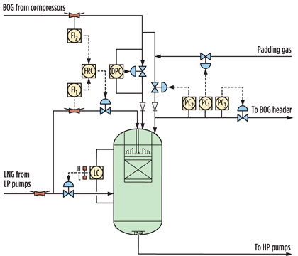
Bottom level and ratio control. All process control examples described so far include LNG flow through the BOG recondenser packed section. At high LNG terminal sendout rates, this can result in a continuous recycle of padding gas from downstream of the LNG vaporizers to maintain pressure in the BOG recondenser, since the LNG sendout rate is significantly higher than that required to recondense all generated BOG.
This operation is not energy efficient; therefore, some annular space type designs have introduced an LNG inlet into the holdup section. This reduces the BOG/LNG ratio in the packed-bed section and minimizes the requirement for padding gas. The downside is that it influences the effectiveness of the auto-regulating effect (when level is maintained predominantly below the packed bed), compared to a BOG recondenser without a bottom inlet.
Some of these annular space BOG recondenser designs have introduced ratio control for the ratio of LNG to the packed bed and BOG. The balance of the LNG goes directly into the holdup section of the BOG recondenser. Since BOG and LNG compositions and temperatures can change, the pressure in the BOG recondenser packed section is a result of the setpoint of the BOG/LNG ratio controller.
Fig. 5 shows the described level and ratio control scheme. The installation of a bottom LNG inlet that is controlled by level can influence the effectiveness of the auto-regulating effect, which is the main feature of the annular space type design. The selection of an annular space BOG recondenser should, therefore, be reconsidered.
 |
|
Fig. 5. Introduction of level bottom inlet and BOG/LNG ratio control. |
Ratio control and pressure override. When the BOG/LNG ratio controller is not programmed and/or configured correctly, there is a possibility that either padding gas will need to be introduced by PC1 (when the LNG-to-packed bed/BOG ratio is too high), or BOG will need to be directed to the BOG suction head by PC3 (when the ratio is too low). Either scenario results in a loss of operational energy efficiency.
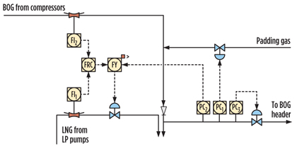
To resolve this issue, overrides from PC2 can be configured to control the BOG recondenser pressure when the bypass valve around the pressure differential controller (i.e., the bypass of BOG to the annular space) is already closed. This scenario is depicted in Fig. 6.
 |
|
Fig. 6. Level bottom inlet control with pressure override. |
Top packed-bed section type
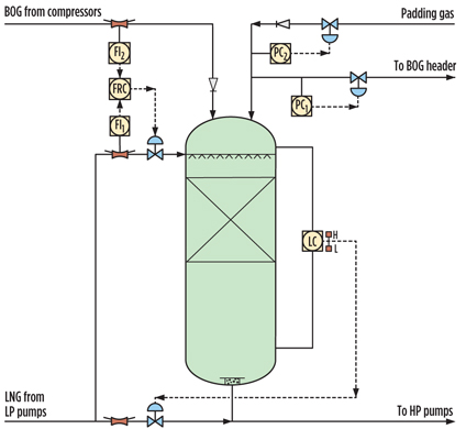
A typical top packed-bed section type of the BOG recondenser is depicted in Figs. 7 and 10. The pressure and level control for this type are depicted in Figs. 2 and 5 of Part 1. Similar to the annular space type, this BOG recondenser receives BOG from the BOG compressors for recondensation, and it also provides holdup and NPSHrequired for the HP pumps.
For the top packed-bed section BOG recondensers, the liquid level is normally below the bottom of the packed bed. As such, the heat transfer area constantly allows for a simple and proven pressure control scheme. To control the BOG recondenser pressure, only some of the LNG is routed to the packed bed, with the balance of the incoming LNG being routed directly to the bottom holdup section. This type of BOG recondenser requires two LNG inlets.
Pressure control. The main objective of the pressure control is achieved by the flowrate of the subcooled LNG from the bottom LNG inlet line to the packed section, to keep the BOG recondenser at a pre-set operational pressure. This control enables stable HP pump and BOG compressor operation. Output from the pressure controller is cascaded as setpoint to the LNG quench (LNG to packed bed) flow controller.
If the pressure increases, then more LNG is routed to the packed bed, reducing the pressure and preventing the opening of the connection to the BOG compressor suction head. If the pressure decreases, then the pressure controller will increase the LNG flowrate via the quench flow controller, to prevent the opening of the padding gas supply. With this type of BOG recondenser, it is easy to adjust the operating pressure of the BOG recondenser (typically between 6 barg and 10 barg) in LNG operations.
When no quench flow controller or flow measurement is provided, the pressure controller can directly act on the quench flow valve. A cascade configuration provides more stability with respect to change in flow, which will be picked up directly by the flow controller before it affects BOG recondenser pressure.
Level control. The LNG liquid level in the BOG recondenser is controlled by manipulating the bottom LNG inlet valve to the BOG recondenser. The level controller can be loosely controlled, since neither operation nor the process requires tight level control in the BOG recondenser.
Process control examples and lessons learned
Process control scenarios can be applied to both types of BOG recondensers, showing control schemes that work, as well as schemes that have failed to work, in practice.
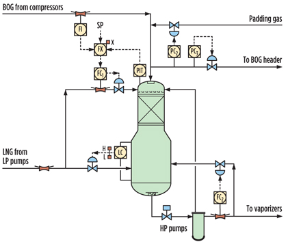
Ratio control with pressure prediction. For both BOG recondenser designs, the BOG/LNG ratio control between the LNG quench flow to the packed bed and the incoming BOG has been applied. Fig. 7 depicts this control scheme for a top packed-bed section type.
 |
|
Fig. 7. BOG/LNG ratio control with the objective to predict operating pressure. |
The objective of this control scheme is to establish a pressure setpoint that is converted into a flow setpoint to the quench flow controller. The scheme in Fig. 7 is a simplification; an implemented control scheme uses a ratio of mass-flow of LNG to BOG, corrected for BOG and LNG quench temperature and BOG recondenser operating pressure. The final volumetric quench flow setpoint is based on actual LNG quench flow density calculations, shown in Eqs. 2–4:
LNGtoBOGmassratio = UncorrectedRatio ×
BOGTCorrection × LNGTCorrection(2)
ActualVolLNGtoBOGmassratio =
LNGtoBOGmassratio / ρLNG(3)
ActualVolFlowLNG = ActualVolLNGtoBOG
massratio × BOGmassflow(4)
The control scheme’s objective is to predict the pressure in the BOG recondenser on the basis of Eqs. 2–4. However, multi-process variable control resulted in an offset between the desired pressure in the BOG recondenser and the actual pressure. This result proved that, even by creating a rigorous mathematical model of the involved thermodynamics, the pressure in the BOG recondenser could not be predicted.
LNG operations then changed the input to the model (i.e., the desired pressure in the BOG recondenser) so that the desired pressure was reached. This resulted in manual feedback control by the operator. For instance, if 6 barg was the desired pressure, the operator keyed 6.32 barg into the distributed control system. However, when the composition changed, the resulting value was 6.65 barg. LNG operations used trial-and-error to achieve the desired setpoint pressure.
Pressure override on ratio control. Some designs for both types of BOG recondensers have a pressure override controller on the BOG/LNG ratio control. When the pressure reaches the HP setting, this pressure controller will take over from the BOG/LNG ratio controller.
As an alternative to this pressure override controller, a pressure controller with a gap could be considered; this controller acts only on the quench on HP to avoid opening the control valve to the suction of the LP compressors. On LP, it acts on the quench to avoid the unnecessary supply of padding gas.
Some fundamental questions to ask are, “If the pressure must be controlled, can a pressure controller be installed on the quench?” and “What are the real advantages and benefits of BOG/LNG ratio control and a floating pressure?” This argument is especially true for the top packed-bed type of BOG recondenser. Furthermore, the original annular space type without a bottom LNG inlet requires a floating pressure for the auto-regulating effect.
By installing the override from PC2, it has become obvious that BOG recondenser control based on ratio control is not essential. Also, the main pressure control is better located on the bypass, and the quench LNG flow should be located at the top (Fig. 8).
 |
|
Fig. 8. Pressure override and padding gas stability. |
Padding gas stability. For stable padding gas control of the BOG recondenser pressure, the padding gas control valves should be installed at a certain distance to the BOG recondenser to provide adequate control time for the control loop to stabilize. Typically, a few seconds are required for the padding gas control loop to stabilize. An unstable padding gas control loop results in violent opening and closing of the valve. In one example, LNG operations decoupled the padding gas control loop due to valve issues.
Full operational bypass without pumps holdup. A BOG recondenser with full operational bypass directly to the HP pump suction is depicted in Fig. 9. In this configuration, the majority of the LNG completely bypasses the BOG recondenser and is fed directly into the suction of the HP pumps, while the balance of the LNG is fed to the packed bed, as required to control the pressure in the BOG recondenser.
 |
|
Fig. 9. Full operational bypass without holdup for HP pumps with operational bypass. |
Successful application of this system has demonstrated that there is no need for substantial liquid holdup in the BOG recondenser. The one potential operational disadvantage of this control scheme is that the LNG in the BOG recondenser can be at bubble-point conditions (rather than subcooled, as is the pumped LNG from the LP pumps), and a sudden inflow of warm LNG (resulting from the interruption of colder LNG flowing directly from the LP pumps) can upset HP pump operations. This upset would happen at a high level in the aforementioned example, where the valve supplying subcooled LNG from the LP pumps is closed, and only relatively warm LNG from the BOG recondenser is fed into the HP pump suction cans.
Control of recondenser bottom pressure. One design that uses bottom pressure control in an attempt to maintain stable suction conditions to the HP pumps is shown in Fig. 10. At a fixed BOG recondenser pressure, the HP pump suction pressure is a direct function of the LNG level, so the PC4 effectively replaces the normal level controller, manipulating the control valve to the holdup section. However, this pressure control scheme is not advised, since 0.5 bar of pressure in the suction needs to be compensated with approximately 10 meters of LNG, which will result in unstable level and pressure control of the BOG recondenser.
 |
|
Fig. 10. Control of BOG recondenser bottom pressure. |
Compressor type and pressure control. The type of compressor chosen—centrifugal or reciprocating—sets requirements on the BOG recondenser pressure control. The more commonly used reciprocal compressors are reasonably insensitive to fluctuations in BOG recondenser discharge pressure.
Conversely, the less commonly used centrifugal compressors can easily move between the surge area (at high BOG recondenser pressure) to the stonewall area (at low BOG recondenser pressure) as a result of discharge pressure fluctuations (Fig. 11). Therefore, when using centrifugal BOG compressors, the BOG recondenser pressure must be tightly controlled.
 |
|
Fig. 11. Typical variable centrifugal BOG compressor curves (either by inlet guide |
Operation and process control takeaway
Several conclusions can be drawn with respect to the information presented on operation and process control of both types of BOG recondensers. For the annular space type of BOG recondenser:
- Various pressure control schemes have been successfully implemented in the industry, and are functional
- An annular space design having an LNG inlet only to the top packed-bed section can suffer from an inverse response when configured to operate on level control only; therefore, total volume control is required for stable operation
- The aforementioned type can also introduce the requirement of continuous recycle of padding gas from the gas sendout system (in the case of high BOG/LNG ratio), at the expense of overall energy efficiency
- To avoid continuous recycle of padding gas to the BOG recondenser, an LNG bottom inlet controlled by level can be introduced at the cost of reducing the effectiveness of the auto-regulating effect
- Selecting a top packed-bed type of BOG recondenser should be considered when a bottom LNG inlet is installed in combination with an annular space type of BOG recondenser, since its main feature, the auto-regulating effect, will not work when the level remains predominantly controlled below the packed bed.
For the top packed-bed section type:
- Trying to predict the resulting operating pressure on the basis of BOG/LNG ratio has proven not to be feasible in practice
- When the operating pressure must be controlled, a simple pressure control loop (see Figs. 2 and 5, Part 1) has proven its effectiveness
- BOG/LNG ratio control is feasible, but pressure remains a fluctuating process variable
- Controlling the BOG recondenser bottom LNG outlet pressure by controlling level has proven to be unstable in practice, since a small change in pressure results in a large change in BOG recondenser level.
For both types:
- For BOG recondenser types with a bottom LNG inlet, BOG/LNG ratio control can be used when a fluctuating pressure in the BOG recondenser is acceptable
- When installing BOG/LNG ratio control and pressure overrides, the designer should consider installing pressure control with a gap, or just a simple pressure control
- For stable padding gas control, the padding gas control valves should be installed at a certain distance to the BOG recondenser to provide adequate time for the control loop to stabilize
- In top packed-bed section type BOG recondensers that have operational bypass directly into the HP pump suction cans, a sudden inflow of warm LNG from the BOG recondenser can disturb HP pump operations
- When a centrifugal BOG compressor is applied, stable pressure control is required to ensure stable BOG compressor operation. The top packed-bed section type with pressure control on the LNG quench is more suitable for this process than is the annular space type.
Less is more. An overview of the most commonly used process control and operational tactics of BOG recondensers reveals the advantages and disadvantages in BOG recondenser operation. BOG recondensers of both types—annular space type and packed-bed type—have been installed and operated successfully.
As a general recommendation, BOG recondenser designers are advised to consider simple designs and operational process control mechanisms.
End of series. Part 1, May/June 2014. GP
Acknowledgment
The author thanks Michiel Baerends from Fluor BV and his colleagues at Vopak LNG Holding BV (part of Koninklijke Vopak NV), as well as Gate terminal BV,
for reviewing the article prior to publication.
SANDER P. B. LEMMERS has more than 17 years of experience in both the technical and business facets of the global engineering, procurement and construction industry. He holds a BSc degree and an MSc degree in industrial engineering and management, and an MSc degree in chemical engineering, from Twente University for Technical and Social Sciences in Enschede, The Netherlands. At present, Mr. Lemmers is involved in the development of LNG and other liquefied gas terminals in Southeast Asia, Scandinavia, France, and The Netherlands.


Comments