
Simplify BOG recondenser design and operation—Part 1
S. P. B. Lemmers, Vopak LNG Holding BV, Rotterdam, The Netherlands
LNG receiving and regasification terminals connect the intermittent process of LNG carrier unloading and/or loading with the mostly continuous process of LNG vaporization and gas transmission into a sendout pipeline system.
In addition to these LNG carrier operations, truck/train loading operations can take place simultaneously. During all operational modes of the LNG terminal, boiloff gas (BOG) is produced, which requires processing to avoid flaring or venting (under normal operating conditions) and to minimize the environmental impact of the facility.
There are several options to choose from for the design of BOG recondensers used in LNG terminals. Design options and equipment installations are reviewed, with a focus on the most optimal methods.
BOG recondensation approach
Of the various options for BOG handling, the most common approach is recondensing the BOG in a BOG recondenser. Discussed are the design, process control and operational elements of the most common types of BOG recondensers used in LNG terminals worldwide.
BOG generation and handling. Generation of BOG takes place in any operational mode of the LNG terminal. BOG is produced mainly because the LNG is stored at cryogenic conditions in a much warmer ambient environment. The generation of BOG is the result of several factors:
- Steady-state heat leak into the LNG carrier, LNG storage tanks, process equipment and LNG process piping
- Mechanical energy input by process equipment [e.g., low-pressure (LP) in-tank and high-pressure (HP) sendout pumps]
- Displaced vapors from the LNG carrier and LNG storage tanks due to unloading, loading and sendout flowrates
- BOG generation and/or reduction due to creation of BOG/LNG equilibrium in LNG storage tanks
- Elevation difference between LNG from the LNG carrier and LNG from the storage tanks
- Atmospheric pressure changes.
The amount of BOG generated is a function of the absolute rates of the above phenomena, and it changes significantly between the various operational modes. The main operational modes of LNG terminals are the holding mode (with gas sendout, but no LNG carrier unloading or loading) and the LNG carrier unloading and/or loading mode(s), also with gas sendout.
Several common options exist for handling BOG generation in an LNG terminal:
- LP compression into a fuel gas system—e.g., for LNG vaporization inside the LNG terminal, for use by nearby industrial consumers or for power generation
- HP compression to natural gas pipeline pressures
- BOG reliquefaction inside the LNG terminal and return as LNG to the storage tanks
- LP compression into a BOG recondenser, in which the BOG is recondensed to LNG.
The last BOG handling option, which focuses on the BOG recondenser, is considered here.
BOG recondensers are commonly applied in LNG terminals where there is continuous sendout of natural gas via vaporization of LNG. Both HP compression and BOG reliquefaction have high capital and operating costs, whereas LP compression requires a substantial nearby consumer of LP fuel gas. However, such a consumer is generally not available.
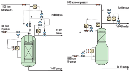
Vapor handling system. The vapor handling system option including the BOG recondenser consists of the BOG desuperheater (required for reducing BOG compressor suction temperature), the LP BOG compressor(s) and the BOG recondenser (Fig. 1).
 |
|
Fig. 1. Process flow of a typical LNG receiving and regasification terminal. |
In the BOG recondenser, the BOG is brought into contact with subcooled LNG for recondensation of the BOG. The LNG is subcooled because the BOG recondenser operates at substantially higher pressures (typically between 5 barg and 10 barg) than the LNG storage tanks, which are slightly above atmospheric pressure.
In the holding mode of operation, all BOG from the LNG storage tanks is routed to the LP BOG compressors, which compress the BOG into the BOG recondenser. During the unloading mode of operation, most of the BOG is returned to the LNG carrier to compensate for liquid volume reduction in the LNG carrier, with the balance going to the LP BOG compressors and the BOG recondenser. The directions of flow are vice versa for the loading mode of operation.
During these main operational modes, LNG is continuously pressurized and vaporized on the sendout pipeline system. When there is no gas sendout, the LNG terminal is in zero sendout mode. In this operational mode, other solutions for BOG handling should be pursued, as the BOG recondenser cannot be operational without LNG sendout for recondensation.
Conventional BOG recondenser designs are based on cocurrent downflow direct-contact packed-bed columns for recondensation, with a holdup section for the downstream HP pumps. They are installed between the LP pumps and compressors and the HP pumps. The setup essentially consists of a partly packed column that has two primary functions. The upper portion houses a packed-bed section in which BOG is contacted with subcooled LNG to recondense the BOG. The lower portion of the BOG recondenser with the holdup section serves as a surge drum for the HP pumps, and the skirt height and level provide the required net positive suction head (NPSH) for the HP pumps.
BOG recondenser design
It is essential to consider practical design elements, such as piping connections, HP pump vents, minimum flow recycle, pressure safety valves (PSVs), vent/flare options and padding gas, for two types of BOG recondenser designs.
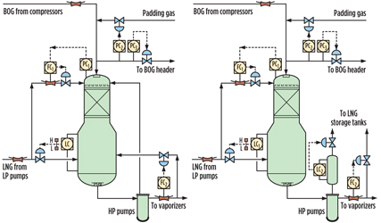
Designs fundamentals. There are two basic designs for BOG recondensers: The annular space type and the top packed-bed section type. Both of these designs operate in the cocurrent downflow regime, which means that both BOG and LNG are introduced at the top of the BOG recondenser and flow downward. The less common countercurrent and static-mixing BOG recondenser designs are not considered here.
Annular space type. This first type contacts the LNG and BOG in a packed bed in the center, surrounded by an annular space. The LNG and BOG are fed to the central packed-bed section. The liquid level in the BOG recondenser annular space is controlled by manipulating the inlet LNG flowrate to the packed-bed section, since all of the LNG is directed to the packed-bed section. The packed-bed liquid level, which is distinct from the level in the annular space (as is the pressure), is not directly controlled and will vary with the BOG/LNG flow ratio in the center section. The LNG levels and vapor pressures in the center section and annular space differ during operation.
Top packed-bed section type. The second type of design has a packed section spanning the complete vessel diameter of the top section, and it has a bottom LNG inlet for the holdup sections of the HP pumps. The single level is controlled via the bottom LNG inlet flow.
LNG for recondensation, which is part of the LNG flow to the BOG recondenser, is introduced into the top packed-bed section and brought into contact with the BOG for recondensation. The pressure in the packed-bed section is identical to the pressure in the holdup section (except for some pressure drop over the packed bed), and it can be controlled by the LNG supply to the top packed-bed section of the BOG recondenser. Fig. 2 shows examples of the two basic types of BOG recondensers.
 |
|
Fig. 2. BOG recondensers: Annular space type (left) and top packed-bed section type (right). |
Mechanical design complexity comparison. From a mechanical design point of view, it is obvious that design and construction of an annular space type BOG recondenser are more complex. The annular packed-bed section needs to be supported from the top and should not vibrate at the bottom.
The top packed-bed section type supports the bed all the way around and, therefore, is more robust. This design features a dedicated removal nozzle for when the packing requires replacement of the top packed-bed section, while the annular space type requires more decommissioning and reinstatement work.
Process piping connections. Although both types of BOG recondenser designs fulfill the same functions—i.e., to recondense BOG and provide NPSH for the HP pumps—the process piping connections to HP pumps, vent/flare, padding gas, PSVs, operational and maintenance bypasses, and control valves can differ from design to design. Designers may even vary the lineup and controls for the same type of BOG recondenser.
Minimum flow recycle and vent connections. The HP pump, being a high-head, multiple-stage canned pump, requires minimum flow protection. The HP canned pump motors are cooled by the LNG. To ensure that the HP pump remains filled with liquid and under cryogenic conditions at all times, the BOG generated from the surrounding heat leak and HP pump mechanical energy is vented. Both the minimum flow recycle and vent lines can be directed either to the BOG recondenser or to the LNG storage tank(s).
Minimum flow recycle to LNG tanks. Directing the recycle back to the LNG storage tanks provides the advantage of no disturbance to the BOG recondenser operation, such as an impact on pressure and level control. It also allows for continued sendout of natural gas when the BOG recondenser is out of operation for statutory inspection or maintenance. When the BOG recondenser is out of operation for inspection or maintenance for a prolonged period of time, the BOG must be vented and/or flared.
However, a 900-pound-pressure-rating, stainless steel head, sized for recycle operation from all HP pumps, needs to be routed from the HP pump area to the top of the storage tanks for this design. This requirement impacts the capital expenditure (CAPEX) of the project, as well as the operational expenditure (OPEX), since the generated BOG from the HP recycle operation requires another cycle of compression by the LP BOG compressors.
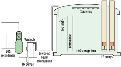
Venting of HP pumps to LNG tanks. When the HP pumps are not located near the BOG recondenser (for example, when an LNG terminal has been revamped and there is no space available next to the BOG recondenser), dedicated vent pots are required for the HP pumps to provide the required NPSH and maintain cryogenic conditions in the HP pump.
The vent pots are provided with reverse-acting level control (wherein vent gas flow from the pot is manipulated), and the outlet of the vent pot is directed to more than one LNG storage tank via a dedicated common vent header. This arrangement not only increases CAPEX, but it also has operational downsides.
If the level control of the vent pots fails, then LNG is spilled into the vent head to the LNG storage tanks, or it can reach the vent and/or flare knockout drum installed at a low point. This is problematic because the vent header generally runs from the vent pots on low elevation over sleepers or a pipe rack to the top of the LNG storage tanks. This setup inherently forms a “low point” in which LNG can be trapped, blocking the free flow of vent gas from the HP pumps. This issue can cascade to vent pot control of other HP pumps, potentially resulting in the warming of the HP pumps. This scenario is depicted in Fig. 3.
 |
|
Fig. 3. BOG recondenser piping connections. |
The introduction of the vent pots with controls also introduces flanges, safety implications for fire and gas, cold protection zones and additional control complexity and maintenance requirements.
Venting of HP pump minimum flow recycle to recondenser. Routing both the minimum flow recycle and the HP pump vents directly to the BOG recondenser provides a simpler design solution, with shorter process connections and fewer process controls, provided that the HP pumps are located in the vicinity of the BOG recondenser. Locating the HP pumps near the BOG recondenser is normally possible during LNG terminal design.
The individual HP pump vents and common HP pump vent header must be continuously sloped to the top of the BOG recondenser to enable free vent gas flow (i.e., bubbles created by excess heat) to the recondenser. No level controls or dedicated vent pots are required, and the level in the common HP pump vent line is equal to that of the BOG recondenser, since these levels are communicating.
Fig. 4 shows the two design examples applicable to both BOG recondenser types. The minimum flow recycle connection from the HP pumps to the BOG recondenser should be brought into the holdup section of the BOG recondenser, and into the annular section for an annular type BOG recondenser. A baffle “impingement” plate should be considered to avoid excess turbulence.
 |
|
Fig. 4. HP pump vent and minimum flow recycle connections to the BOG recondenser or tank(s). |
However, the alternative of bringing the HP pump minimum flow recycle to the packed section is not recommended, since this process lineup will disturb the pressure controls in the top of the BOG recondenser during HP pump recycle operation.
Please note that routing the recycle and vent connections to the BOG recondenser is only feasible if there is no need for continued LNG terminal sendout operations when prolonged shutdowns (i.e., statutory periodic inspections) cannot be avoided.
Padding gas connection. Padding gas, taken from downstream of the LNG vaporizers, is required to maintain a minimum pressure in the BOG recondenser for maintaining required NPSH and stable HP pump operation. BOG is supplied to the top of the packed section. Therefore, the most logical location to introduce padding gas is the BOG inlet connection, and all mechanical support and internals for receiving gas from the top are already designed and installed for this purpose. The introduction of padding gas at any other location (e.g., underneath the packed bed or directly into the annular space) requires an additional nozzle on the BOG recondenser, as well as additional mechanical internal design and reinforcements of the packed bed.
Introducing padding gas underneath the packed bed makes sense if the bed can be blocked by fouling. However, the BOG recondenser service is one of the cleanest in the oil and gas industry, and blocking of the packed section by fouling is not feasible. Padding gas can always be safely introduced from the top.
Pressure safety valve connection. The connection to the PSV should be on the top of the BOG recondenser, preferably from the BOG inlet connection, for similar reasons as the padding gas supply connection (i.e., the additional nozzle, and no possibility of blocking the packed bed due to fouling). Connecting the PSV underneath the packed bed is often proposed; this stems from refinery services where mist mats and packed sections can be blocked due to fouling.
However, LNG and BOG services are very clean. The PSV comes in a twin configuration to enable online maintenance, since the BOG recondenser forms a single point of exposure for LNG terminal availability.
Operational bypass. Some BOG recondenser designs apply an operational bypass, in which a portion of the LNG from the LP pumps bypasses the BOG recondenser and flows directly into the HP pump suction cans. This is done to decrease the size of the holdup section (for any given holdup section residence time) and to reduce vessel costs. Such a bypass is technically feasible since not all of the LNG is required for BOG recondensation.
However, the introduction of an operational bypass does require additional flow controls that will open the bypass when the flow through the BOG recondenser increases above the design flow through the bottom section. Therefore, instrument functions, control valves and cold-keeping bypasses must be added to the design. In Fig. 5, a flow controller (FC2), associated controls and hardware are added to the design when an operational bypass is installed. Experience shows that the added cost offsets the CAPEX savings from the BOG recondenser size reduction.
 |
|
Fig. 5. BOG recondenser operational and maintenance bypasses. |
Reductions in the BOG holdup section (and, therefore, the BOG recondenser size) are usually possible without an operational bypass, simply by reducing the holdup time from traditionally conservative values. Experience has shown that holdup time is not critical; designs with zero holdup time that pump LNG directly into the HP pump suction are in operation. Designs where all of the LNG passes through the BOG recondenser require a higher LNG control valve turndown than do designs with an operational bypass.
Inspection and maintenance bypass. Authorities sometimes impose the statutory requirement for scheduled internal inspection and BOG recondenser entry, even for a clean and noncorrosive service like BOG recondensation. To enable vessel entry and inspection while continuing sendout operation (with inevitable temporary venting/flaring of BOG), a maintenance bypass for LNG around the BOG recondenser, cold-keeping bypasses and positive isolation must be introduced. During this operation, the HP vent and HP pump minimum flow recycle can only be diverted to the tanks, requiring the installation of an additional means of venting the HP pumps (i.e., vent pots).
Due to the various disadvantages associated with the installation of a maintenance/inspection bypass for statutory inspection, many projects ask to be exempt from the standard requirements for vessel entry and physical inspection. Instead, these projects propose a reliability-based online inspection. Projects should ask for this exemption at the start so that the exemption is available during the design stage, and so that CAPEX for maintenance bypasses and isolation valves can be eliminated.
Platforms and control valves at grade. Some designs use platforms and have control valves installed at these elevated platforms. The introduction of many platforms at several levels not only increases the cost, but it also complicates operations and maintenance. It is recommended to have piping dressed/clipped on the BOG recondenser, and to avoid the use of concrete/structural steel platforms, as a means of reducing the overall project cost.
In addition, it is beneficial to operations and maintenance to install control valves as often as possible at grade level. Recently installed control valves have much better turndown than previous designs, and they eliminate the need for control valves to be in a split-range configuration. The reduction in the amount of required control valves, brought about by this improved turndown, reduces the need to introduce more platforms.
Platforms will be congested, complex and more complicated to operate and maintain when there are many of them, and also when the control valves around the BOG recondenser form a single point of exposure (requiring the BOG recondenser operation to stop upon failure) when they are supplied with bypass.
In one industry example, control valves were passing and leaking at a top platform level. Workers discovered the leaking valves only because they heard noises at grade level. Therefore, by installing more platforms, significant operational issues may go undetected.
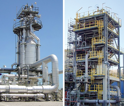
Fig. 6 shows a design with minimal platforms, where the only reason for workers to climb to the top platform of the BOG recondenser is to conduct PSV inspection and maintenance.
 |
|
Fig. 6. BOG recondenser design with minimized platforms and control valves at grade (left) vs. a traditional platform design (right). |
Design takeaway
A few conclusions can be drawn from the preceding discussion of BOG recondenser design:
- From a mechanical design point of view, an annular space type of BOG recondenser is more complex and, therefore, likely more costly
- Minimum flow recycle and vents on HP pumps should be routed to the nearby BOG recondenser, rather than to the LNG storage tanks, to minimize operational complexity and CAPEX:
- HP pump vent pots (required for venting to LNG storage tanks) introduce flanges, fire zones and operational difficulties when the level control fails
- Running the minimum flow recycle for the HP pumps back to the LNG storage tanks introduces a costly, 900-pound-pressure-rating return line
- No separate padding gas connections to the BOG recondenser are required; padding gas should enter through the BOG inlet connection
- The BOG recondenser service is clean, and the packed bed cannot foul up; the connection to the PSV should, therefore, be installed on the BOG inlet line, which eliminates the requirement of a dedicated nozzle
- It is doubtful if the installation of an operational bypass actually saves costs, as the bypass comes with control valves, cold-keeping bypasses, and additional process control complexity, which largely offsets the savings
- from a reduced BOG recondenser holdup volume
- It is strongly recommended to ask for exemption of statutory BOG recondenser inspection and entry from authorities; when such an exemption is granted, a costly maintenance bypass may be eliminated from the project
- To reduce costs and complexity, control valves should be installed as often as possible at grade, minimizing the number of platforms
- Piping to the BOG recondenser should be dressed/clipped as much as possible.
Less is more. An overview of the most commonly used design methods for BOG recondensers reveals the advantages and disadvantages in BOG recondenser design. BOG recondensers of both types—annular space type and packed-bed type—have been installed and operated successfully.
As a general recommendation, BOG recondenser designers are advised to consider simple designs, as discussed in Part 1 of this article. Part 2, to be published in the July/August 2014 issue, will examine the operational aspects of BOG recondensers. GP
Acknowledgment
The author thanks Michiel Baerends from Fluor BV and his colleagues at Vopak LNG Holding BV (part of Koninklijke Vopak NV), as well as Gate terminal BV for reviewing the article prior to publication.
Sander P. B. Lemmers has more than 17 years of experience in both the technical and business facets of the global engineering, procurement and construction industry. His technical competencies include the engineering and design of LNG production and regasification facilities, offshore oil and gas production, gas compression platforms, ethylene cracking complexes, gas purification and NGL recovery processes. His business competencies include knowledge of management information systems, management accounting, sales coordination, strategic business planning and business risk management. He holds a BSc degree and an MSc degree in industrial engineering and management and an MSc degree in chemical engineering from Twente University for Technical and Social Sciences in Enschede, The Netherlands.
At present, Mr. Lemmers is involved in the development of LNG and other liquefied gas terminals in Southeast Asia, Scandinavia, France and The Netherlands.


Comments