
Reduce LPG sulfur with a ‘rules of thumb’ checklist
T. Temur, Ş. Avcılar, E. Özinan and M. Karakaya, Tüpraş, Kocaeli, Turkey
Processing sourer opportunity crude oils leads to increased sulfur carryover to desulfurization and demercaptanization units in refineries worldwide. For this reason, the liquefied petroleum gas (LPG) treatment plant has an essential role in a refinery for meeting product sulfur specifications and for environmental compliance, regardless of the declining margin of the product itself.1, 2
The treatment process, often referred to as sweetening, involves the liquid/liquid extraction of the mercaptans (RSH) in LPG with a caustic solution, which is regenerated by oxidation with air in the presence of a liquid catalyst. For the refiner, it is important to reuse this regenerated caustic to the maximum extent to save on operating costs and to stay within product specifications.
In general, operating parameters of LPG treatment units are not closely monitored by plant or process engineers. The reasons for this oversight include insufficient focus due to reduced profit margins and a lack of well-defined, practical insight into the process due to varying upstream conditions and challenging analysis of sour samples.
The following case history addresses a solution to high sulfur levels in product LPG at the Tüpraş Izmit refinery in Turkey. A checklist of parameters for LPG treatment—each of which must be evaluated on a periodic basis—is also proposed.
Case history
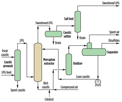
The flow scheme for the LPG treatment plant under consideration is shown in FIG. 1. Mercaptans in the LPG feed are counter-currently extracted with a downflowing caustic solution in the extractor column, which is preceded by a caustic prewash tower in case hydrogen sulfide (H2S) is present in the feed. The caustic settler drum and the sand filter are respectively used to drain the caustic and reduce the sodium salts that are carried over to the sweetened LPG product.
 |
|
Fig. 1. LPG mercaptan extraction and caustic regeneration process. |
In the caustic regeneration section, air and liquid catalyst are injected into the mercaptide-rich caustic solution from the bottom of the extractor, and the mixture is fed to an oxidizer column, where the extracted mercaptans are oxidized to disulfides (RSSR). The disulfide oil, caustic solution and spent air are separated in the disulfide separator. Caustic is circulated back to the extractor, spent air is incinerated and the disulfide oil is sent to the slop tank.
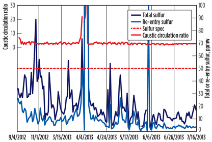
FIG. 2 shows laboratory analysis and operational data pertinent to the LPG treatment process from September 2012 to mid-July 2013. Total sulfur refers to the weight sum of all mercaptans, sulfides, disulfides and other sulfur compounds (e.g., carbonyl sulfide) contained in the product LPG, whereas re-entry sulfur is defined as the sum of dimethyl and diethyl disulfides only.
 |
|
Fig. 2. Sulfur test results and caustic-to-hydrocarbon ratio. |
As shown in FIG. 2, the product had gone off-spec several times due to total sulfur content, thereby considerably affecting the sales volume. Moreover, until early June, sulfur content, on average, was observed to be very close to the regulatory limit of 50 ppmw, if not off-spec—a situation that left no room for processing sourer feedstock.
Operating parameters
Major process parameters were reassessed so that actions could be taken to resolve the problem and stabilize the operation, and also so that future areas for improvement could be identified. These parameters are considered, along with their effects on extractor performance.
Circulating caustic. The mercaptan-removal ability depends on the concentration of unneutralized sodium hydroxide in the caustic solution, which then limits the amount of spent caustic. This spent limit, typically in the range of 10 wt%–20 wt%, can be reduced to increase the circulation rate of free caustic, and, therefore, the extraction rate.
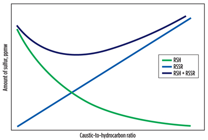
The volume of circulating caustic relative to the volume of LPG feed—referred to as the caustic-to-hydrocarbon ratio—also affects the total sulfur content. As this ratio increases, a certain amount of LPG is contacted with more caustic to give a better mercaptan-extraction performance, as indicated by the exponentially decreasing curve shown in FIG. 3 for an arbitrary system.
 |
|
Fig. 3. Change of product sulfur content with caustic-to-hydrocarbon ratio. |
FIG. 3 also shows that re-entry sulfur in the product increases linearly with the caustic circulation rate, or caustic-to-hydrocarbon ratio, since the entrained disulfides in the regenerated caustic are almost completely removed by the LPG exiting the extractor. This means that there exists a single optimum value, usually in the range of 1 vol%–3 vol%, for the caustic-to-hydrocarbon ratio where the total sulfur amount is minimized. Above this ratio, the transfer of re-entry sulfur into the product can be inadmissible; below it, mercaptan extraction can be inadequate.
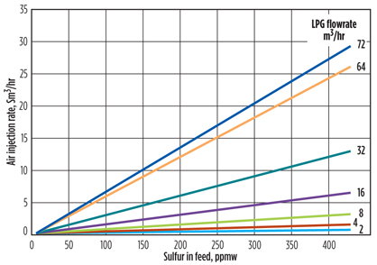
Injected oxygen. The amount of air, which is the source of oxygen (O2) required in the oxidizer, determines the extent of regeneration. While the mercaptide content in the regenerated caustic must be small, total regeneration is not a good practice because excess O2 may lead to corrosion in spent air and disulfide lines. Another reason is that O2 dissolved in the caustic potentially sweetens the mercaptides in the extractor, increasing the disulfides in the product. This scenario suggests that the rate of air injection should be adjusted, as the LPG flowrate and mercaptan content vary (FIG. 4).
 |
|
Fig. 4. Air injection rate expressed as a function of feed flowrate and mercaptan content. |
Catalyst concentration. The oxidation rate of mercaptans to disulfides increases with the catalyst concentration. Catalytic oxidation activity can be partially determined with a visual test (called a “shake test”) that involves filling half of a glass bottle with the regenerated caustic and shaking it until the color of the solution changes from blue to green.
The color change, which normally takes place at around 60 seconds under typical oxidation conditions of 42°C and 50% excess air, happens when the degree of oxidation changes for cobalt. If this change takes longer than 120 seconds, then catalyst addition will be required to maintain the activity. The licensor’s operating manual suggests an optimum catalyst-to-circulating caustic ratio of 0.25 kilograms (kg)/1,000 cubic meters (m3).
Temperature. Operating the extractor at lower temperatures in the range of 32°C–38°C gives the best mercaptan-extraction performance, since demercaptanization is a set of exothermic equilibrium reactions. Below 32°C, caustic entrainment by hydrocarbon may be a problem. Above 38°C, insufficient extraction will result.
Regeneration is a typical catalytic oxidation process where the rate increases dramatically, even with a slight increase in the operating temperature. Therefore, to avoid acid formation and corrosion of equipment due to over-oxidation, the oxidizer should always be kept at the lowest temperature limit that gives the desired degree of regeneration. The oxidizer inlet temperature should be between 38°C and 43°C.
Attacking LPG sulfur
Referring back to FIG. 2, the main component to total sulfur in the product is analyzed to be re-entry sulfur, a fact that helps pinpoint where to attack the problem. To minimize re-entry sulfur, several actions were taken in accordance with the guidelines for the aforementioned operating parameters.
Setpoint for caustic-to-hydrocarbon ratio. Prior to early June 2013, the LPG treatment unit had been operated without control on the caustic flow, which fluctuated between 2 vol% and 10 vol%. Upon consultation with the process control engineers, the caustic-to-hydrocarbon ratio was fixed at 2.5% (FIG. 2).
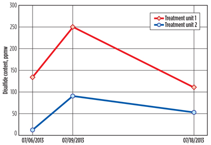
The amount of circulating caustic was seen to also affect re-entry sulfur, when the disulfide content of the regenerated caustic stream from another LPG treatment plant was considered. The plants have the same hydrocarbon processing capacity; however, treatment unit 1, described in this work, accommodates less caustic by design, which leads to a separation bottleneck in the regeneration section.
FIG. 5 shows the amount of disulfides at the exit of the separator, measured soon after caustic batch changes. This clearly indicates that the amount of circulating caustic—or, more practically, the caustic renewal rate in unit 1—needs to be increased. According to common practice, this rate was once every two weeks prior to June 2013; after this time, the rate was increased to once per week.
 |
|
Fig. 5. Disulfide content in the regenerated caustic streams of different LPG treatment units. |
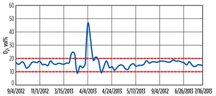
Air injection rate. Another source of disulfides in the product is sweetening of mercaptans in the extractor, which is a consequence of excess oxygen dissolved in the regenerated caustic. A nomogram similar to the plot in FIG. 4 was prepared to aid the operators in adjusting the air injection rate required during oxidation. This eliminated the fluctuations in the concentration of the O2 in the disulfide lines, keeping it in the 10 vol%–20 vol% range (FIG. 6).
 |
|
Fig. 6. O2 content in the disulfide stream leaving the separator. |
Catalyst addition and temperature. To maintain the catalytic activity in the oxidizer, the catalyst-to-circulating caustic ratio is set at 0.25 kg/1,000 m3. Depending on the shake test results, catalyst is added.
Extractor and oxidizer temperature ranges vary between 32°C–38°C and 38°C–43°C, respectively, but in the solution of the high-level sulfur problem, variations in these ranges were discarded since they fell within the operating window.
As shown in FIG. 2, the amount of total sulfur in the product LPG decreased drastically as a result of the operational measures taken, and it settled on a stable line. Not only did these measures result in on-spec LPG production, but they also facilitated the processing of sourer opportunity crude oils upstream of the LPG treatment plant. GP
Literature cited
1US Energy Information Administration, “Heating oil and propane update,” March 2013.
2Emkay Global Financial Services Ltd., “Oil & Gas Sector Update.”
 |
Tolga Temur is an operations superintendent who has worked with Tüpraş since 2008. He is responsible for crude oil, vacuum, fluid catalytic cracking (FCC) and LPG treating plants. Mr. Temur also has experience in hydrodesulfurization and gas treatment processes. His studies include the optimization of ejector systems and amine regeneration systems. He holds a BS degree in chemical engineering and an MS degree in fuel and energy technologies from Boğaziçi University in Istanbul, Turkey.
 |
Şeyma Avcılar has been working as a process engineer at Tüpraş since 2012. She is responsible for the FCC process while participating in projects on gas and LPG treatment plants. She received BS degrees in chemical engineering and chemistry in 2010 and an MS degree in chemistry in 2013 from Boğaziçi University in Istanbul, Turkey.
 |
Ecem Özinan joined Tüpraş as a process engineer in 2012. She is responsible for amine treating, sulfur recovery and Merox processes. Ms. Özinan also has experience in kerosine treating and selective hydrogenation processes. She holds a BS degree in chemical engineering and is pursuing an MS degree in fuel and energy technology from Boğaziçi University in Istanbul, Turkey.
 |
Mustafa Karakaya, PhD, is a process superintendent with Tüpraş’ R&D Center. He received his BS and MS degrees and PhD in chemical engineering from Boğaziçi University in Istanbul, Turkey. His professional and research interests include computational fluid dynamics design, analysis of refining processes and equipment, assessment and improvement of furnace operations, and modeling and optimization of catalytic processes.


Comments