
Examine inlet separation technologies for increased reliability
D. B. Engel and S. Williams, Nexo Solutions, The Woodlands, Texas
Contamination ingression into gas processing units is one of the most prevalent modes negatively affecting plant operations. To enable plants to run with minimal instabilities, increased capacity and high reliability, it is necessary to perform inlet separation to remove unwanted contaminants in the gas feed prior to processing.
Several feed separation approaches must be considered to determine the appropriate action mode. Feed inlet separation methods include the characterization and evaluation of inlet contaminants, process conditions and variability, expansions, space and maintenance aspects, and various separation technologies. All of these elements help ensure that the feed gas meets processing conditions, and they also help increase gas plant reliability and capacity over the long term.
Contaminant characterization. In many cases, the characterization of the feed contaminants in the context of the process and the evaluation of any existing or planned inlet separation systems reveal one of two issues. They show that either upgrades to existing equipment are necessary to improve performance, or, in extreme cases, new systems are required.
Here, inlet and feed conditioning technologies and concepts for gas processing operations are described for the most common contaminants.1 It is important to choose the proper contamination separation pathway for the mitigation of these contaminants. It is not possible to discuss all devices in one article; however, information on the most relevant technologies is provided, based on extensive field experience with the most frequently used equipment in the field.
The most complex inlet contaminants present in raw natural gas are compressor lubrication oil liquids, in the form of submicron aerosols. These oils are some of the main culprits for gas processing plant upsets, such as foaming, which leads to non-compliance with H2S specifications for sales gas. Off-specification product results in lost revenue and emissions via gas flaring.
Compression systems in gas plant inlets, refineries, transmission lines, chemical plants and other industrial settings are an integral part of the operation. Without the achievement of required system pressure, the process cannot operate as designed. Compression systems in refinery fluid catalytic cracking units (FCCUs) are generally responsible for more than 40% of a refinery’s capacity, and failure can even lead to complete refinery shutdowns, causing tens of millions of dollars per day in lost revenue.
Natural gas compressor stations are responsible for the transportation of raw and processed natural gas, and they supply the pressure needed for gas plant operations. Compression system protection is, therefore, an extremely important aspect of successful plant operation, as compressor failure or contamination bypass both have substantial consequences.
Lubrication oils typically contain 90% base oil (these are most often petroleum fractions, called mineral oils) and approximately 10% additives. Additives deliver reduced friction and wear, increased viscosity, and improved viscosity index, as well as resistance to contamination, corrosion, oxidation and aging. However, most additives also have surfactant properties, causing a number of downstream problems (e.g., foaming).
Base oil, which is usually a heavy hydrocarbon, causes detrimental effects downstream. These effects are related to the agglomeration of the heavy hydrocarbon with solid particles in the gas stream, forming larger residues. This material can cause deposition and fouling in gas lines and downstream equipment, including pumps, compressors and metering equipment. In fact, these contaminants are often responsible for inaccurate gas metering, which generates considerable revenue losses.
To illustrate this point, Fig. 1 shows the change in surface tension of pure water when contacted with lube oil. The decrease in surface tension from 72 millinewton/meter (mN/m) to
46 mN/m, at 25°C, is a clear indication of the surfactant properties of water-soluble additives in the lube oil. The decrease in surface tension leads to an increase in entrained water and dissolved contaminants downstream as separation equipment loses liquid removal efficiency. Poor liquid removal efficiency leads to downstream issues, including foaming, fouling and corrosion, in addition to process solvent losses and performance decay.
 |
|
Fig. 1. Effect of the surface tension of pure water compared to when water is contacted with lubrication oil at 25°C. |
Feed conditioning technologies in gas processing operations can come in many different forms. The most commonly used technologies are:
- Two- and three-phase horizontal bulk separators (also known as inlet receivers)
- Demisters (also known as knockout drums, and to some extent similar to the inlet receivers)
- Cyclonic/centrifugal separation systems
- High-efficiency coalescers
- Filters.
The most common configuration in gas processing plants comprises a three-phase separator followed by a cartridge gas/liquid coalescer. A filtration system is often included between the separator and the coalescer if solids are prevalent. Most two- and three-phase separators are equipped with additional internals that impart different functionalities, such as mesh pads or vane packs for large liquid droplet separation. These internals provide a dual functionality in a single vessel. In essence, inlet receivers separate bulk contaminants, while filters and coalescers provide the final polishing.
Two- and three-phase separators. Inlet receivers or separators are vital to plant operations as they are the first piece of separation equipment that will encounter and remove contaminants. These vessels are designed to remove bulk liquids, some liquid water slugs, and, by association, certain solid materials. No other piece of equipment can properly replace these functions with the capacity of inlet receivers.
The correct sizing, internal design and internal features are critical to ensure that downstream feed conditioning devices do not overload their capacity, and also to ensure that the plant itself operates with a balanced split of contaminant removal at the various conditioning stages. Field experience has shown that gas/liquid coalescers are often overburdened with contaminants that should have been removed upstream at the inlet receiver, so the fundamental importance of the receiver should not be disregarded.
Inlet receivers are often sized based on the correct parameters, but a lack of proper understanding of liquid and solid loading in terms of variability, composition and liquid droplet/particle size is common. In gas processing, inlet separators are generally horizontal, three-phase separators (Fig. 2) that remove liquids from gas streams [typically down to 50 microns (µm)–150 µm] and separate liquid water and hydrocarbon. It is widely accepted to have a horizontal, cylindrical vessel with an inlet on one side and a gas outlet on the other to provide maximum residence time and minimal carryover.
 |
|
Fig. 2. A horizontally oriented three-phase inlet gas separator. |
To properly design an inlet separator, a number of essential factors must be considered:
- Vapor capacity
- Liquid capacity
- Operability
- Efficiency.
The vapor capacity is determined by the volume needed for gravitational forces to remove the liquids entrained in the stream from the gas phase. This process is influenced by the density of the gas and liquid(s), the fluid viscosity and the droplet sizes.
Gas Processors Association guidelines should be used to determine the vapor capacity and the vessel size. The sizing equations used in these guidelines (Eq. 1) are partially based on Stokes’ law, and they can be used to optimally size a separator for the specified droplet size required for removal and length, diameter or length-to-diameter (L:D) ratio:
 (1)
(1)
The liquid density (ρl, lb/ft3), gas density (ρg, lb/ft3), minimum droplet diameter desired for removal (Dp, ft), and fluid viscosity (μ, cP) must first be specified. These factors can then be used to determine C*, a factor based on the drag force on the droplet, which is then correlated to Cʹ, the actual drag coefficient.
The actual drag coefficient, the factors first specified, and the acceleration due to gravity (g, ft/s2) are then used to determine the terminal velocity (Vt, ft/s) of liquid droplets. Finally, the volumetric fluid flow (QA, ft3/s) must be specified. This factor, along with the terminal velocity and a specified vessel diameter (DV, ft), can be used to determine the vessel length necessary for the efficient removal of droplets of the specified diameter. It is recommended to optimize these equations using a set specification for droplet size and a specified diameter that gives an optimal L:D ratio.
The liquid capacity is typically set by determining the volume required to provide adequate residence time to de-gas the liquid, or to allow immiscible liquid phases to separate. Liquid capacity is influenced by the incoming rates of hydrocarbon and/or water, and is accommodated for in the size of the vessel and the height/position of the weir separating the hydrocarbon from the water.
Operability issues include the ability of the separator to deal with solids (if present), unsteady flow and liquid slugs, turndown and others. Level control instrumentation and monitoring are critical to mitigate these issues. Finally, the optimal design for efficiency will usually result in a set of features that satisfies these requirements for a specific process conditions window at a reasonable cost. A drawing of a common three-phase inlet gas separator (with optional internal coalescing plates, used only when there is minimal solids-induced fouling) is shown in Fig. 3.
 |
|
Fig. 3. Depiction of internals and flow scheme for an effective three-phase inlet gas separator. |
The vessel interior is designed to ensure proper liquid-phase separation of water and hydrocarbon. An inlet baffle should be installed that distributes flow evenly throughout the vessel, but it must be designed so that it does not promote liquids shattering as a result of shear forces acting on the droplet surface upon entry. Wave breakers should also be installed to homogenize slugs and prevent liquids carryover.
Mesh pads and/or vane packs should be installed at the vessel outlet, and they must be designed correctly (as discussed in the following section). Nozzle velocities should also be maintained below erosional velocity (in accordance with American Petroleum Institute Recommended Practice 14 E guidelines) to avoid nozzle erosion corrosion and/or liquids shattering that produces smaller-size liquid droplets.
Separation technologies based on pressure decay, velocity changes and residency time are among the most common separation systems used in gas operations. All of these technologies have the common theme of using relatively simple concepts to meet a separation requirement. A large number of different vessel designs are available, with many different features, including the presence of a bottom boot, different weir arrangements and sizes, different inlet nozzles, and numerous gas outlet features.
Some of these vessels do perform properly if designed correctly and operated within the design limits. Several of these systems, however, display deficient performance caused by improper designs. For example, inlet baffles that cause liquids shattering or route the gas directly toward the outlet, causing carryover, are fairly common. Changes in feed gas parameters, along with the poor operation of the separator outside the design parameters for flow and pressure, or both, will also cause significant contamination breakthrough. If these factors are present in combination, then the problem is greatly exacerbated.
Water contamination in gas feeds can also be extremely detrimental to processing facilities, as it can carry significant quantities of dissolved contaminants. In some situations, water from feed gas can have thousands of mg/L of dissolved solids (salts), causing downstream issues. Salts are a main cause of compressor failure. Fig. 4 shows the interior of a compressor exposed to water with salts in the feed gas stream, causing solids deposition in its interior.
 |
|
Fig. 4. Interior of a failed compressor exposed to produced water contamination. |
Inlet gas plant receivers in operation today are not designed to accommodate large amounts of water along with gas condensate. This was the case for raw natural gas streams a few decades ago, when water was not as prevalent; however, water is now more common and present in higher amounts. Inlet receivers should, if possible, be modified to face this new feed gas contamination reality. New vessels should incorporate larger water volumes into their design criteria during the early stages of the project.
Designs that incorporate metal mesh internals to promote coalescence and decrease residence times often show negative to marginal results due to poor understanding of streams with high fouling tendency (i.e., streams having tenacious, adhesive and deformable solids). Fig. 5 shows fouled internal corrugated plate elements for liquids coalescing. Detailed internal design with respect to hydrocarbon separation is also an area of weakness; many vessel fabricators do not consider proper location and sizing for the internal hydrocarbon removal element (box or weir).
 |
|
Fig. 5. Fouled internal corrugated plate element for liquids coalescing in a three-phase separator. |
Other common design deficiencies encountered in inlet separators include a lack of wave breakers installed for liquids splashing and deficient instrumentation location to sense interfaces. However, the most common deficiency is a vessel that is undersized for the application. Undersized vessels cannot be upgraded or reconfigured. In terms of vessel size, it is always recommend to consider future capacity scenarios and to incorporate sizing parameters conservatively.
Demisters, mesh pads and vane packs. Common in the industry are separation systems for liquid contaminants in gas streams carried out using vertical vessels (demisters) equipped with a metal coalescing pad, elements or vane packs installed near the outlet of the vessel. Fig. 6 shows a general diagram and a picture of a demister knockout drum.
 |
|
Fig. 6. Schematic (left) and photo (right) of a vertical demister knockout drum system. |
These systems are only adequate for removing large-diameter-contaminant droplet sizes above 20 µm–30 µm, depending on the design and internals. In fact, these separators were originally designed for bulk liquids removal (small slug catchers). These devices are not designed for solids separation (which is usually done by a wet scrubber or a particle filter), with the exception of cyclonic systems that can remove large solid particles and some larger liquid droplets. Mesh pads and vane packs in these systems (Fig. 7) do not have a fiber/vane size or density to interact with small submicron aerosols.
 |
|
Fig. 7. Wire mesh pad (left) and vane pack (right) for use in demisters and inlet separators. |
Mesh pads suffer from flooding when excessive liquids are introduced, and the mesh becomes saturated with liquid. This leads to efficiency losses by carryover. Mesh pads are also prone to solids fouling by particle deposition at the mesh structure surface, further reducing their efficiency and causing considerable maintenance costs and failures.
Movement of the mesh pad inside the vessel is somewhat common due to the difficulty of properly anchoring these devices to the vessel interior. Mesh pad design should also consider liquid (i.e., water and liquid sulfur) and solid (i.e., iron sulfide gels and coke fines) properties and concentration, in addition to internal flow geometry. Disregard of these aspects will lead to element flooding and liquid carryover or fouling, along with differential pressure increase. To use coalescing mesh pads correctly, they must be designed according to the gas velocity across the pad using the modified Souders-Brown equations (Eq. 2):
![]() (2)
(2)
The liquid density (ρl, lb/ft3) and gas density (ρg, lb/ft3), as well as a gas capacity factor (K, ft/s), must first be specified. The gas capacity factor is based on the minimum droplet size for removal specified for the installed pad, but the most common average wire thickness and density designs have a K factor between 0.2 ft/s and 0.4 ft/s; designs that are more efficient will have a lower K factor.
The K factor, as determined based on the mesh pad characteristics, should then be derated based on the system pressure (i.e., 90% of the design value at 150 psig, 85% at 300 psig, 80% at 600 psig and 75% at 1,150 psig). The K factor and gas/liquid densities can then be used to determine the maximum gas velocity across the pad (Vt).
Finally, the optimal mesh pad cross-sectional area for gas flow can be determined by dividing the specified volumetric flowrate (QA, ft3/s) by the gas velocity through the pad. The depth of the pad, along with the wire thickness and density, is dictated by the desired minimum droplet size for removal. Pad depth can be determined by the supplier once the cross-sectional area for gas flow is calculated.
The Souders-Brown equations can also be used for the sizing of vane packs. The only difference in sizing between the two designs is the determination of the gas capacity factor K. The most commonly used vane packs have a K factor between 0.9 ft/s and 1 ft/s in the horizontal flow configuration, and a K factor between 0.4 ft/s and 0.5 ft/s in the vertical flow configuration. It is important to note that the K factors for vane packs are higher than those for mesh pads because vane packs generally are not as efficient at removing liquids.
Vane packs have better mechanical performance and lower differential pressure than mesh pads, but they provide inferior separation efficiencies. Vane packs are ineffective as they form an interface layer at certain points, and small aerosols cannot effectively contact the metal surface. The small momentum of the aerosols also contributes to the inefficiency.
Vane packs are especially ineffective when dealing with submicron liquid aerosols, since the small droplets do not have enough momentum to properly contact the vane surface. Most small droplets are carried with the stream. The presence of interfacial layers in many vane packs and some mesh pads are one cause of such inefficiencies, and companies have mitigated this by using different designs, such as double and single pockets. Efficiencies can be enhanced somewhat for larger liquid droplets, low liquid loadings and gas velocities within certain limits.
Mesh pads and vane packs have small operating windows and are prone to fouling and loading. These inefficiencies are also seen in other systems that use poor coalescing elements, incorrect media and materials selection, and deficient vessels from the standpoints of design, instrumentation, operation and maintenance. Even in modern developments, where improvements are made by a combination of vane packs and mesh pads, the removal efficiency is not adequate to protect sensitive equipment and processes.
Also important to these devices is the inlet mode to the vessels. Many companies have developed inlet distributors to provide a more homogeneous flow to the demister element (mesh pad or vane pack). These devices will also not cause liquid shattering. It has been shown (via computational fluid dynamics and field testing) that some of these distributors are needed to provide a consistent and homogenous distribution of the gas flow into the demister element, offering a more balanced separation process and minimizing the possibility of carryover.
Cyclonic separation systems. Cyclonic separation systems (Fig. 8) function by enhancing the acceleration of solid particles and liquid droplets, and by enhancing gravitational forces with a centrifugal or cyclonic component. This process increases the rate of solid/liquid and liquid/liquid separation from the gas phase.
 |
|
Fig. 8. Flow scheme and rotational effects in a typical gas cyclone. |
These devices do not have moving parts and can endure high process temperatures. The feed enters the system tangentially, and a rotational effect is created by the vessel shape that spins solids and/or liquids in the gas to the outside of the vessel, toward a bottom outlet, while creating an inner vortex that carries purified gas out of a central top outlet. These systems can be used in some feed gas conditioning applications where solids filtration and/or bulk liquids removal systems are ineffective.
There are several forms of gas cyclonics, and each has its advantages in certain situations. In relation to feed gas conditioning, the predominant forms of gas cyclones used are inlet cyclones, horizontal inline separators, vertical recycling separators, multi-cyclones and mass-transfer cyclones. Cyclones will generally perform in accordance with design specifications when designed properly, and will do so in a repeatable, predictable manner. Problems that occur usually are not with the design of the cyclone, but with improper application of the system. Issues arise when cyclonics are used for the wrong loading conditions, or for contaminants that are not mechanically sound or aerodynamically conducive for separation.
A number of factors must be accounted for in the design of a cyclone, including the feed composition, temperature, pressure and flow, as well as the contaminant density, size distribution and physical properties. The desired differential pressure, as well as the removal efficiency, should also be considered and accounted for in the system design. However, feed conditions are not always conducive for a cyclonic system of any kind.
Additionally, cyclonic systems have a somewhat narrow operating window, and it is suggested to have a good understanding of the service in which they are intended to be used before their specifications are finalized. Cyclonic devices do not handle large variations in the feed effectively unless they are initially designed with additional criteria.
One aspect of increased applicability of cyclonic devices is at the inlet of inlet receiver vessels or coalescers. It is believed that, in inlet receivers, there are advantages to incorporating inlet cyclonic elements for better emulsion and foam handling. In principle, the inlet cyclonic elements will enable better multi-flow separation into the vessel.
Another use of these elements is in the first stage of separation in a dual-chamber coalescer. The use of multiple small cyclones (mini-cyclones) is believed to separate large liquids from the gas prior to coalescing in the second stage. Purely cyclonic devices are also available from many vendors if the requirements are to remove large liquids from a gas stream. To date, the effectiveness of many of these devices in the field has not been tested, and no representative data regarding their actual efficiency is available. Recently, emerging technologies like centrifugal inlet separation systems have been under development. These novel options should soon be made available to the industry.
High-efficiency cartridge coalescers. Today, the technology of choice for high-efficiency removal of submicron aerosols (also known as mists) that negatively plague gas streams in gas processing operations is coalescing devices using microfiber media materials, or microfiber submicron coalescers. These microfibers can effectively interact or intercept with small aerosol liquid droplets. If the coalescer element is built correctly, the intercepted liquid will be effectively coalesced and drained from the element, avoiding flooding and further liquids re-entrainment.
In theory, high-efficiency submicron coalescers should be capable of removing, on average, 99.98% to 99.9998% of all aerosols with diameters between 0.1 µm and 1.0 µm (or larger), as measured in a laboratory setting. In essence, this is the majority of the liquid aerosol contamination in many points of gas processing operations, such as compressors and, to some extent, amine absorber outlets. Microfiber submicron coalescer devices (Fig. 9) are quite sophisticated and must be carefully designed based on the flow, pressure and temperature (both operational and design); they must also be installed as close as possible to the asset requiring protection.
 |
|
Fig. 9. Schematic of a liquid/gas demister (left) and a high-efficiency submicron coalescer (right). |
Correctly designed vessels have two stages—the bottom inlet section designed to remove bulk liquids, and an upper high-efficiency stage for aerosol removal. In certain situations, the bottom section can be fitted with a mesh pad or vane pack, or designed in such a way as to have cyclonic action.
The gas leaves the bottom chamber, flowing into the second stage immediately above via the coalescing elements’ interior, and is then directed across the microfiber coalescing media. The fine aerosols are intercepted, coalesced and finally drained from the elements by gravity. Like the lower stage, the upper stage has a liquid removal system comprising a level control and drain valves. The purified gas exits from the top of the vessel.
For the fabrication and operation of a successful microfiber submicron coalescer, a correct vessel design is critical. The vessel is much more complex than a filter. Some aspects to consider are ensuring proper inlet velocity (below 60 ft/s) and avoiding baffles that promote liquids shattering. It is also necessary to have correct internal flow geometry and velocities, both across the media and while exiting the coalescing elements.
In liquids removal, there is always a competitive mechanism between the gravitational draining of the liquids from the coalescing element surface (or interior) and the drag force exerted by the exit gas. If the drag is too high, then carryover will likely occur. Gasket compatibility and design, as well as correct instrumentation, also play pivotal roles. Failure in any of these areas will render the vessel ineffective, causing contamination breakthrough.
One aspect to consider carefully is vessel size. The vessel size is generally part of the design; however, due to its fundamental effect in gas processing operations, it will be discussed separately. For the most part, undersized vessels in filtration will lead to higher clean differential pressure, shorter online life and high filtration costs.
In the case of coalescing systems, however, the effect is much more profound. Undersized vessels will lead to high velocities in the vessel interior, directly affecting contamination breakthrough; this is one of the reasons coalescers should never be undersized. If inadequate size is compounded by poor internals and other vessel deficiencies, then the inlet separation process efficiency can be reduced to nearly zero.
Since these systems are of great importance for the gas industry, it is essential to mention turndown aspects. Field testing indicates that these devices can, in principle, have a turndown of 90%, but operational observations have shown that this turndown is closer to 70%. Below that mark, the system becomes unstable, and such turndown rates are not recommended without prior testing.
Typical campaign times for gas coalescing elements can vary from six months to two years, depending on the amount of solids entering the coalescing stage, and also the additive presence. Chemical additives, such as corrosion inhibitors, can change the surface properties of the coalescing media in such a way that separation is rendered ineffective. These devices should be protected with a suitable particle filter (equipped with the correct separation media) to extend the online life of the coalescer and to minimize operational costs, as the replacement filter elements for particle separation are much less expensive than are coalescing elements.
Horizontally oriented coalescing systems, commonly referred to as filter coalescers (Fig. 10), are also used for inlet separation. However, field testing indicates that this orientation is less effective for inlet separation, and more effective in pipeline applications where high efficiency is not required. Depending on the design, horizontal orientation offers no location for bulk liquids removal without affecting the coalescing elements. The out-to-in flow is less effective and inhibits proper control of gas velocities in the vessel. Horizontal coalescers require the coalescing elements to make up the first chamber, and the second chamber requires a mesh pad or a vane pack to intercept and drain coalesced droplets.
 |
|
Fig. 10. Horizontally oriented high-efficiency gas/liquid coalescer. |
Coalesced liquids from the elements themselves do not have a location for drainage, and the mesh pad or vane pack in the secondary section will not intercept and drain droplets as efficiently as do the elements themselves in a vertical configuration. Finally, the drain for coalesced water to the liquid reservoir is at the end of the vessel, in close proximity to the gas outlet; this proximity often leads to increased liquids carryover.
It is important to mention that key considerations are required when designing the drain and level control systems to ensure that the elements remain clear of liquid, whereby saturation of the elements (at the bottom section of the coalescing element in a vertical system) would render them ineffective for proper liquids removal.
Finally, even the best coalescing devices can be ineffective if the instrumentation and control schemes are not functioning properly. Some systems will actually lack instrumentation, while others may have incorrect instrumentation in place. The location of instrumentation is important since some units in cold locations have no protection; they often freeze and provide incorrect readings.
Proper monitoring of differential pressures is important since it is the only way some vessels communicate. Gas/liquid coalescing systems usually will have a terminal differential pressure between 8 psi and 10 psi. Operation beyond that point will reduce coalescing, ultimately leading to element bursting and liquids bypass.
Filters. As seen in many cases of poor contamination control, the leading cause of poor performance is a defective vessel design. Defective design can occur in many forms:
- Undersized vessels
- Unbalanced array of internals, causing preferential flow
- Incorrect internal flow geometries
- Incorrect placement of inlets or outlets
- Erroneous vent or drain locations
- Incorrect support thicknesses, causing vessel internal failure
- Lack of internal baffles, causing lateral impacts into the internal elements and media rupture.
In some cases, certain vessels can be modified, upgraded or improved. However, for undersized vessels, there is no practical solution to avoid exponentially high operational costs. Filtration in gas streams is, for the most part, simple to perform when done properly and with prior understanding of the contamination profiles.
For example, some gas streams will have elemental sulfur as a contaminant that must be filtered, and the mode of filtration is, therefore, surface filtration with accommodation of large solid mass quantities. Less media and more open volume for solids separation is fundamental. In other cases, it is necessary to have large surface areas because the solids deposition is predominantly iron sulfide, which commonly produces a smaller layer of solids deposition. In other cases, where asphaltenes are present, a thin layer will form over the media, requiring enhanced surface area.
As far as media selection is concerned, many good materials are available. Metal media is more expensive, offers lower effectiveness at small particle sizes and is difficult to clean, but it is reusable to some extent, provided that there is no aggressive fouling of the metal surface. Disposable woven materials are not recommended for gas applications due to the mobile filter matrix, and non-woven materials (i.e., disposable filters) are available with a fixed media fiber array. Non-woven materials include impregnated cellulose, cotton, glass fiber and nylon, among others.
Gas filtration media should impart great mechanical resistance because of the elevated-momentum solids that can rupture the soft media, if present. A critical aspect in gas filtration applications, besides the type of solids and filter cakes expected, is the compatibility (chemical, thermal and mechanical) to the stream and the stream contaminants. Filtration in gas services is usually exposed to significant vibrations; therefore, securing the internals is highly recommended. A properly designed filter for feed gas conditioning is shown in Fig. 11.
 |
|
Fig. 11. Schematic drawing of a filter vessel for proper feed gas conditioning. |
The inlet to the vessel is positioned at the same level as the filter element risers to allow the risers to distribute the flow evenly through the vessel and avoid direct impingement of the inlet flow on the elements. The flow through the elements is generally outside-in, as it accommodates more elements per vessel volume to ensure that the flux through each element is not too high. The tube sheet that holds the elements in place has smaller holes with more spacing in between them, since the sheet is accommodating the inner diameter of the elements in an out-to-in flow. This design gives the tube sheet more structural integrity and allows elements to be packed in the vessel at a higher density. The out-to-in flow also gives more filtration surface area, especially when pleated style elements are used.
Sizing should be done with regard to the velocity of the gas stream across the media (media face velocity), the pressure, and the temperature. Clean pressure drop across the inlet and outlet nozzles, the tube sheet and the element should also be accounted for in the system design to allow maximum lifetime. Nozzle velocities below 60 ft/s should be maintained to avoid erosion-corrosion effects.
Filtration efficiency has always been an area of nebulous recommendations for both gas and liquid streams. Experience has shown that reported filter efficiencies might not be particularly relevant. Filter efficiencies are generally a product of laboratory experiments under controlled conditions using a sole and uniform contaminant. Whether this laboratory efficiency is applicable to real process conditions is still not clear.
The only way to ascertain desired filter efficiency is to perform tests on systems in operation. This method considers the measurement of particles and contamination levels at the inlet and outlet of the filter. Filter optimization is performed only under real operating conditions, by adjusting the media efficiency, based on real-time fluid analysis. It is also recommended to match the particle distribution of the solid contaminant to the media in terms of efficiency and micron sizes. Considering filter lifetime (and cost) is also critical. In the absence of such information, it is best to start with a given filter at the lower efficiency and to increase the efficiency as needed based on periodic sample analysis.
Elements with a poor design and a less-than-optimum media surface area will have a reduced contamination capture capacity and low online life, requiring frequent maintenance. This scenario also generates higher waste volumes and results in higher operational costs.
Excess media surface area in a filter element will also cause reduced contamination capture capacity, as a phenomenon called media “blinding” takes place. Media blinding occurs when parts of the media experience ineffective exposure to the fluid stream. Media efficiency selection is also an area where a number of failures occur due to a poor understanding of the tradeoffs in terms of separation cost vs. the downstream effects of contamination penetration. It is always critical to understand why a given contaminant is required to be removed and what the operational expectations of the filter are at the location where it will be installed.
Another area many times disregarded is related to instrumentation. Filters have differential pressure limits that must be verified for accuracy (usually 25 psid to 35 psid). Operation beyond this point can lead to element collapse and contamination bypass.
Inlet separation testing and analysis. The first step in proper inlet separation is the understanding of the contamination profile in the stream. In most instances, gas testing and contamination testing and analysis are vital pieces of any design and/or troubleshooting protocol. Contamination in the feed gas contributes to a variety of effects, both in the separation systems installed and downstream, so the identification of contaminant ingress should be performed in almost every case. Suspended solids, water with dissolved contaminants, additives and other liquid contaminants (such as heavy hydrocarbons and lubrication oils, among many others) should be determined, quantified and analyzed for minimization at the source, if possible—or, alternatively, for the deployment of a suitable feed separation system, if required.
Liquid contamination in gas streams is one of the most common and crucial challenges. Compression systems introducing lube oils, additives, heavy hydrocarbons and produced water all cause detrimental downstream effects, and they must be identified and quantified before a removal solution can be developed.
The testing for liquids in gas streams is performed quantitatively using a gas/liquid super coalescer test system (Fig. 12). The system consists of a high-pressure (HP) housing that contains the coalescer element (with a super-coalescing media array). The gas flow is routed from the HP feed point into the coalescer system, separated from solids and liquids, and then sent to a low-pressure point. As gas flows across the multilayer coalescing media element, the liquids are intercepted, coalesced and drained from the element. At the bottom of the test system, there is a site glass with an inner reservoir to accommodate the drained liquids. The site glass is calibrated to measure liquids accumulation. Liquids can then be removed from the system by means of a needle valve.
 |
|
Fig. 12. Setup of the gas/liquid super coalescer test system for a compressed gas stream. |
The separated liquids are analyzed for composition and concentration, and a better understanding of process challenges can be gained. Routing of the gas into an HP membrane will isolate the solids in the stream. Both liquids and solids can be further analyzed. Calculations are done carefully to compensate for air/natural gas differences and to extrapolate contamination loadings from the coalescer systems to the main gas flow. The test is always performed in an isobaric mode, and it can also be performed in an isokinetic mode.
The nucleus of the test is the coalescing element. The test elements have specialized media formulations that impart super-coalescing properties. The efficiency of the elements is rated at 99.98% for liquid droplets down to 0.1 µm in size, up to 99.9998%, depending on test needs. The elements also have the latitude for the separation of liquids with a broad spectrum of polarities and viscosities.
With advanced testing for liquid contaminants using the coalescer system, coupled with suspended solids characterization, a thorough contamination characterization can be completed and used for the design or improvement of virtually any inlet separation system. In all cases where feed contamination is present, it is advisable to locate the source. Often, a capital investment can be avoided by identifying and correcting issues upstream. If possible, avenues for reducing feed contamination should be investigated before an investment is made in capital-intensive equipment.
Inlet separation configurations. In terms of contamination in gas streams, liquids are predominant at inlet points compared to solids, so most devices focus more on liquid contamination as opposed to solids contamination. Liquids removal systems, such as demisters equipped with vane packs, mesh pads, low-performance coalescers and cyclones, are relatively ineffective at capturing submicron aerosols (0.1 µm to 1.0 µm). However, if these systems are used for other purposes (e.g., pipeline applications, bulk separation, slug separation), then they can be very effective.
For the feed gas conditioning process, the final polishing stage is vital, as it deals with contamination that can cause serious plant upsets. As indicated in Fig. 13, about 50 wt% of all liquid contaminants in a gas stream at the outlet of a compressor are smaller than 1 µm (aerosols range), and 80 wt% are smaller than 10 µm. Aerosols between 0.1 µm and 1.0 µm in size are the most penetrating and difficult to remove. The reason for this challenge is that there is an absence of a proper separation mechanism in place for their removal. The reason for the lack of efficiency of many coalescer devices in removing small-size submicron aerosols from gas streams is related to their inability to interact with these small-size liquids, and to the deficient flow configuration inside the vessel.
 |
|
Fig. 13. Typical liquid aerosol size distribution in a gas stream at the outlet of a compressor. |
The vessel design, instrumentation and gaskets are also fundamental for correct liquid contamination removal. In many instances, the equipment choice and separation internals and media could be appropriate, but if the liquids removal from the vessel or the internal flow pattern is deficient, then the vessel will experience a decrease in efficiency and carryover. Additionally, some defective vessel designs may actually shatter large liquids in the gas stream, producing much smaller droplet sizes and adding difficulty to the separation process. Gasket material degradation is a main reason for liquids bypass, and this aspect should be reviewed carefully. Finally, instrumentation plays a fundamental role in liquids sensing and withdrawal from the vessel, and it should be inspected periodically and monitored carefully.
Today, the technology of choice for high-efficiency inlet separation and removal of submicron aerosols in gas streams is built around formulated microfiber glass fiber media. Vane packs, cyclones and mesh pads should only be considered for larger liquid aerosols with droplet sizes well above 10 µm. Nonetheless, these devices are ideal for bulk liquid removal (slug catchers) or as a pre-separation to a more efficient stage downstream.
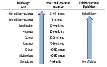
Fig. 14 shows the various technologies that can be used for inlet separation and their associated lower-end liquids separation size, based on field experience and testing. These efficiencies are average, and, depending on the service, can vary to higher or lower sizes. This list is designed to be a starting point and guide for further refinement.
 |
|
Fig. 14. Typical liquid droplet sizes removed by various separation technologies (averaged empirically). |
A proper inlet separation setup usually comprises a large-capacity vessel for bulk liquids removal (usually a three-phase separator for gas, condensate and water). This separator will also act as a slug catcher. These vessels should be equipped with a mesh pad or vane pack for liquids coalescing and inlet cyclonic elements. These devices are almost always required and should not be avoided; however, they should be used only for bulk liquids removal and large-entrained liquids removal.
A filtration system sized to accommodate the solids loading in the feed should be installed downstream of the inlet separator and upstream of the polishing coalescer. The filter should be designed to remove virtually all feed solids if a high-efficiency coalescer is to be installed downstream. Downstream of the filtration system, there should be a microfiber submicron coalescer separator (generally, a cartridge type). This system should be equipped with specially formulated microfiber coalescing media that has the ability to remove submicron aerosol liquids.
High-efficiency coalescing is a vital part of any gas feed conditioning system and should be implemented in almost every case where critical protection is required (i.e., the amine inlet, the dehydration inlet, the mercury removal inlet, the CO2/CH4 membrane inlet, and the compression inlet/outlet). Preliminary feed testing and performance testing of equipment is also highly recommended to ensure proper systems design and internal selection, and to verify contamination removal efficiency once the systems are operational.
Takeaway. A key step in process control is proper contamination control. Most plants that do not take this step struggle with high operational costs and low systems reliability, and they incur many detrimental technical, economic and environmental effects.
There are no notable disadvantages to implementing enhanced inlet separation, aside from marginal increases in capital cost and footprint. There are, however, many serious issues that arise from neglecting inlet separation systems, using systems with deficient designs, using low-cost systems and/or not giving the proper attention to contamination in the feed. Any capital savings gained from the use of low-cost inlet separation equipment will ultimately lead to higher processing costs, low reliability and frequent unit upsets. In turn, these issues will lead to off-spec sales gas and profit losses.
It is also important to understand that each plant and process has its own contamination ingression profile and process conditions. Operators, engineering firms and suppliers have the responsibility to be involved in finding the best strategy for contaminant removal, with the objective of supplying the right inlet separation system for each individual application.
Holistically, knowing and understanding the operation of the plant, and why a given separation system is required, is fundamental for designing, troubleshooting, optimizing, operating and maintaining inlet separation systems. This knowledge will allow plant operators to take full advantage of the installed process capabilities and to maximize throughput while lowering operational costs and minimizing losses. GP
Acknowledgments
The authors would like to acknowledge Ken Winton (Bechtel), Van Barclay (JCI Process), Mike Sheilan (Sulphur Experts), and Heath Burns (Filtration Experts) for their assistance with this article.
Literature cited
1Engel, D. B. and M. H. Sheilan, “Choose optimal feed conditioning strategies for gas processing,” Gas Processing, January/February 2014.
 |
David Engel has more than 20 years of industrial experience in the chemical and process industries. He is the inventor in 17 US patents and he has developed business and technology for Eastman Kodak, Eli Lilly, Pentair, General Electric and Sulphur Experts globally. He has also presented seminars and technical courses on a variety of subjects. Dr. Engel is the managing director of NexoSolutions. He holds a BS degree in industrial chemistry and a PhD in organic chemistry, and he is the president of the American Filtration and Separation Society, Southwest Region.
 |
Scott Williams is a process engineer at Nexo Solutions. He holds a BS degree in chemical and biological engineering from the University of Colorado at Boulder, and he has expertise and experience in areas including process design and troubleshooting, analytical technology, thermodynamic modeling and simulation, phase separation, filtration and separation.


Comments