
Determine compressor settling-out conditions for recycle gas loop design
S. Katkar, Foster Wheeler Asia Pacific, Singapore
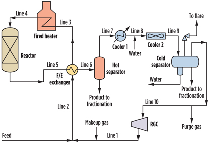
The recycle gas compressor (RGC) is one of the most important pieces of equipment in hydrotreaters, hydrocrackers and catalytic reformer units. A typical reactor recycle gas loop used in a hydrotreater unit is shown in Fig. 1. This loop consists of a reactor, a fired heater, a feed/effluent exchanger, a product cooler, a separator drum and interconnecting piping.
 |
|
Fig. 1. Process flow of a typical recycle reactor gas loop. |
Design conditions of RGC loop equipment are not only based on maximum operating conditions, but also on settle-out conditions, which can be defined as the equilibrium pressure and temperature when the compressor is tripped. These conditions are neither the compressor discharge conditions nor the compressor suction conditions, but something in between.
Note: This reaction recycle gas loop typically includes one pressure relief valve (PRV) on the separator drum to protect the entire system, provided the code requirements are met. The foremost code requirement is that equipment components should not be blocked from being protected. If any blockages exist, then they must be positively controlled.
Compressor settle-out pressure1 is also used for deciding the design pressure of the separator drum and eliminating the applicability of the compressor failure contingency for the PRV.
American Petroleum Institute (API) Standard 5212 explains the procedure to determine the design pressure of these equipment pieces based on settle-out pressure; however, the procedure to calculate the settle-out pressure varies by engineering company.
Procedures in use for determining settle-out conditions and establishing design pressure for equipment components in recycle gas loop systems are discussed here, using data from case studies.3
Determining settle-out conditions
The settle-out pressure and settle-out temperature are the pressure and temperature in the recycle gas loop system when the gas flow is suddenly stopped after the RGC is tripped. It may take 20–30 seconds for the entire system to reach final settle-out conditions. The determination of settle-out conditions is an approximate estimate based on conservation of mass and the following considerations:
- Reaction recycle gas loop end-of-run (EOR) conditions, such as temperature, molecular weight and pressure drop, are generally more severe than start-of-run (SOR) conditions; therefore, settle-out conditions are typically determined for the EOR case.
- The recycle gas loop is assumed to be completely isolated, with no inflow or outflow of material streams, such as makeup and purge gas.
- Only vapor/gas volume is considered to be available during the settle-out process. Liquid volume remains as is, and does not need to be considered.
In Fig. 1, recycle gas from the RGC is mixed with a feedstream, which is then heated in the feed/effluent heat exchanger and the fired heater before entering the reactor. The reactor effluent is first cooled in the feed/effluent heat exchanger before being separated in the hot separator. Gas from the hot separator is further cooled in coolers 1 and 2, and then finally separated in the cold separator. Gas from the cold separator is compressed by the RGC and recycled back to mix with the feedstream. Note: This configuration may change based on the specific purpose and technology involved; however, a typical reactor recycle gas loop will consist of the above elements.
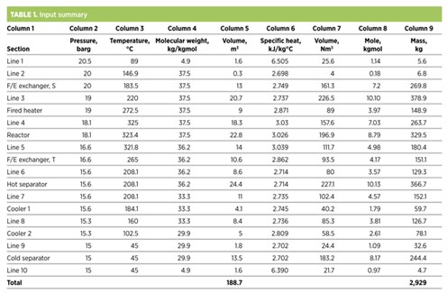
Depending on the availability of known data, several methods can be used to determine the settle-out conditions. Each method involves segregating the entire system into different pressure and temperature sections. In Table 1, Column 1 represents the sections for the reactor recycle gas loop. Columns 2 through 6 represent information consolidated from the heat and material balance, equipment specifications and other engineering documents.
Simulation method
This method, which uses tools available in certain commercial simulation programs, can be treated as the most appropriate method for determining the settle-out conditions. The simulation method requires either complete simulation or, at minimum, information on the composition of the sections (as shown in Column 1) to generate these sections in a simulation. The steps involved in this method are as follows:
- Generate streams in the simulation representing each section, using pressure, temperature and composition, as shown in Table 1. Note: Equipment temperature is considered as the average of the inlet and outlet temperatures.
- Adjust the mass of each stream to match the volume of that section, as per Table 1, Column 5, on a per-unit time basis.
- Fix all of these streams together to generate a combined stream (mixture stream).
- Generate another stream (settle-out stream) that has the same mole and heat flow as that of the mixture stream.
- Adjust the pressure of the settle-out stream so that the volume of the settle-out stream is the same as the total system volume.
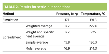
The adjusted pressure and corresponding temperature of the settle-out stream will represent the settle-out pressure and temperature. Table 2 shows the results of this method.
Spreadsheet method
The simulation method may not always be the ideal choice, for several reasons:
- The proper simulation package is only available
- from a licensor
- The exact composition to generate the sections in the simulation method is unavailable
- An appropriate simulation program is unavailable.
In these cases, the spreadsheet method can be used to determine the settle-out conditions.
The spreadsheet method is based on a combined gas law. For simplicity of calculation, compressibility is assumed to be the same as z = 1 for all gas streams. The combined gas law is shown in Eq. 1:
![]() (1)
(1)
The steps involved in this method are as follows:
- Using data from Table 1, columns 2 through 5, and the combined gas law, Eq. 1 can be applied to determine the normal volume (in Nm3) for each section. This volume is represented by Table 1, Column 7.
- Using normal temperature and pressure conditions (1 kgmole = 22.414 Nm3) and data from Table 1, Column 7, the kgmole can be determined for each section. This measurement is represented by Table 1, Column 8.
- The mass in each section can be determined using data from Table 1, Columns 4 and 8. This mass is represented by Table 1, Column 9.
- An alternative way to determine the mass of each section, where compressibility values are known, is to use an ideal gas equation as shown in Eq. 2:
![]() (2)
(2)
Assuming that considerable mixing will occur during the settle-out process, there are different ways to determine the mixture temperature and the settle-out temperature, as shown in Eqs. 3–6.
Simple average temperature:
TS = AVERAGE (Ti) (3)
Weighted average temperature:
![]() (4)
(4)
Weight and specific heat average temperature:
![]() (5)
(5)
Molar average temperature:
![]() (6)
(6)
Note: Eq. 4, weighted average temperature, is the most widely used method for calculating the mixture temperature.
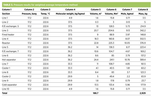
After determining the temperature, the pressure of the system can be altered until the present mass of the system is the same as the system’s original mass. Table 3 shows this result, using weighted average temperature as the settle-out temperature for all sections.
Determining the design pressure
Since it is not economical to design all equipment in the recycle gas loop to a single point of high pressure, API Standard 521 gives a procedure to calculate design pressure for this equipment.2 As per the API standard, the design pressure of the separator drum/RGC suction drum should be calculated as 1.05 times the settle-out pressure, which provides an adequate margin between the operating pressure and the set pressure of the PRV. It also gives an acceptable margin for the compressor failure contingency.
 |
|
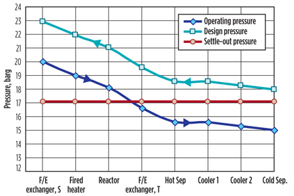
Fig. 2. Pressure profile for the EaOR case. |
Using this calculated separator design pressure as a base, and referring to the pressure increments in the EOR case, the design pressure of other pieces of equipment can be established. Fig. 2 shows the operating pressure for the EOR case, and the settle-out pressure and design pressure for the recycle gas compressor loop equipment. Process engineers sometimes provide an additional margin for new units, instead of the standard 1.05 times the settle-out pressure, to cater to future capacities. GP
Nomenclature
F/E exchanger=Feed/effluent exchanger
PO=Operating pressure, bara
VO=Operating volume, m3
TO=Operating temperature, °K
PN=Normal pressure, bara
VN=Normal volume, Nm3
TN=Normal temperature, °K
TS=Settle-out temperature, °C
Ti=Operating temperature of individual section, °C
mi=Mass of individual section, kg
ni=Moles of individual section, kgmole
Cpi=Specific heat capacity of individual section, kJ/kg°C
Literature cited
1API Standard 671, “Axial and centrifugal compressors and expander-compressors for petroleum, chemical and gas industry services, 7th ed., July 2002, and API Standard 618, “Reciprocating compressors for petroleum, chemical and gas industry services,” 5th ed., December 2007. Per API Standards 617 and 618, settling-out pressure is the pressure of the system when the compressor is shut down without depressurizing of the system. Settling-out pressure must be provided by a process engineer working with the centrifugal compressor, as this measurement is necessary for the vendor designing the seal system. The author recommends also providing settling-out pressure for reciprocating compressor, as this measurement is required for determining the starting torque of the driving motor.
2API Standard 521, “Pressure-relieving and depressuring systems,” 5th ed., January 2007.
3Heydari Gorji, A. and H. Kalat Jari, “Calculating settle-out pressure in compressor loops,” Hydrocarbon Processing, November 2006.
 |
Santosh Arvind Katkar is a principal process engineer at Foster Wheeler Asia Pacific Pte Ltd., based in Singapore. His specialty is process design, and he has 15 years of experience in the refinery, petrochemical and chemical process industries, with leading engineering organizations such as Jacobs Engineering Group, Fluor Corp. and Lurgi AG. Mr. Katkar earned his MTech degree from the Indian Institute of Technology in Delhi, India, and his BTech degree from the University Institute of Chemical Technology in Jalgaon, India.


Comments