
Select valves for LNG use as transportation fuel
B. P. Hood, Flowserve Corp., Houston, Texas
Due to its high energy density, LNG is fast becoming a viable choice for transportation fuel. It is being adapted for use in vehicle engines and for high-horsepower applications. LNG’s usage as a transportation fuel—and, specifically, the valve and control designs used in LNG production, storage, distribution and refueling—is examined here.
Trends in LNG transportation fuel. In 2009, the movement of goods and people in the US consumed 13 million barrels per day (MMbpd) of oil, and is projected to use in excess of 14 MMbpd by 2015, representing 70% of total US oil consumption.1 Two-thirds of this consumption was in the form of gasoline, and the balance was diesel.2
With new, abundant resources of natural gas in North America from shale formations, the use of natural gas in both LNG and compressed natural gas (CNG), as alternatives to gasoline and diesel, is beginning to grow. With more infrastructures to support CNG refueling, the trend in North America is moving LNG toward higher-consumption applications, including long-haul trucks, railroad locomotives, large-mine hauler trucks, marine applications and land-based oil production platforms.
The case for using LNG is often favorable due to:
- High energy density
- High fuel consumption offering cost savings
- Reduction in environmental impact
- Growing network of LNG fueling points
- Easy adaptation of diesel units to utilize dual-fuel diesel/LNG or full LNG technology
- Proven cryogenic valve technology being used in the LNG chain.
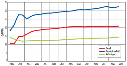
Although LNG has a lower energy density than an equivalent quantity of diesel (1.7 gallons of LNG provides the same energy output as 1 gallon of diesel), the cost saving is still significant. Moreover, gas prices are expected to remain lower than diesel prices in the future (Fig. 1).
 |
|
Fig. 1. Projected growth in fuel prices to 2035. Source: US Energy Information |
An additional advantage for operators using LNG is reduced emissions of CO, CO2, NOx, VOCs and particulates.
The US Environmental Protection Agency has issued EPA 40 CFR 1068, more commonly known as Tier 4 emissions regulations for offroad diesel engines.3 Using LNG as a fuel would ensure compliance with these regulations.
It is anticipated that high-horsepower applications will drive infrastructure growth, micro-liquefaction plant construction, storage and refueling of tanker fleets, providing the baseload for applications like the conversion of long-haul trucking to LNG.
Valve designs for LNG applications. LNG, at a temperature of −162°C, requires valves designed for cryogenic service. Design considerations include positive shutoff and venting of the valve cavities due to the 600:1 expansion ratio of cryogenic liquids when they become gaseous.
Valves used in LNG transportation fueling systems are typically gate, globe and ball designs. Materials used in these valves must remain ductile at cryogenic temperatures, and the two most common materials are brass and 316 stainless steel. Body materials may be forged or cast. Seat and seal materials must also be designed to operate at cryogenic temperatures, and are typically polytetrafluoroethylene or similar polymer or polymer blends.
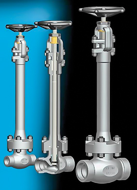
Cryogenic valves are typically installed vertically and use a stem extension to insulate the stem seals from the liquid cryogen, thereby ensuring that the seals maintain good stem sealing. Non-extended cryogenic valves may be used on applications for intermittent or short-duration use.
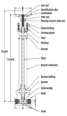
Gate valves (Fig. 2) are used on storage tanks, including fixed storage tanks, vaporizers and mobile tanker trailers. They are a rising-stem, multi-turn design using a metal-to-metal gate to wedge against the body and seal. Polymer or elastomer sealing elements are not used. They are typically used as manual valves for isolation. Their advantages are:
- Lower cost
- Metal-to-metal backseat on the stem when fully open
- Metal-to-metal sealing.
The disadvantages of gate valves are:
- The cost to automate due to their multi-turn operation
- Difficulty of repair
- Flow opening and closing times.
 |
|
Fig. 2. Gate valve. Image courtesy of Flowserve Corp. |
In addition, gate valves tend to have a lower stem seal lifecycle, with potential stem seal leakage associated with a rising stem design.
Globe valves (Fig. 3) are also used extensively in these applications. They are a rising-stem, multi-turn design using a plug and polymer seal against a central port in the body. They are typically used as manual valves for isolation and throttling. Their advantages are:
- Lower cost
- Replaceable seal on the stem
- A metal-to-metal or polymer backseat on the stem when fully open.
The disadvantages of globe valves are:
- Cost to automate due to their multi-turn operation
- Slow opening and closing times
- Lower stem seal lifecycle
- Potential stem seal leakage due to rising-stem design.
 |
|
Fig. 3. Globe valve. Image courtesy of Flowserve Corp. |
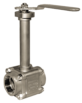
Ball valves (Fig. 4) are used widely in these applications and also in fueling connections. The ball valve is a quarter-turn design using a ball captured between two polymer or metal seats. They are typically used for rapid open-and-close operation due to the quarter-turn operation. Their advantages are:
- Quarter-turn operation easily automated electrically or pneumatically
- Ease of repair
- High lifecycle stem seal
- Ease of throttling.
 |
|
Fig. 4. Ball valve. Image courtesy of Flowserve Corp. |
Disadvantages include no stem back seal (as found in rising-stem valves) and a slightly higher cost than gate and globe valves.
Applications. Valve applications in LNG systems for transportation and high-horsepower applications can be broken down into four operations:
- Liquefaction
- Storage
- Distribution
- Refueling.
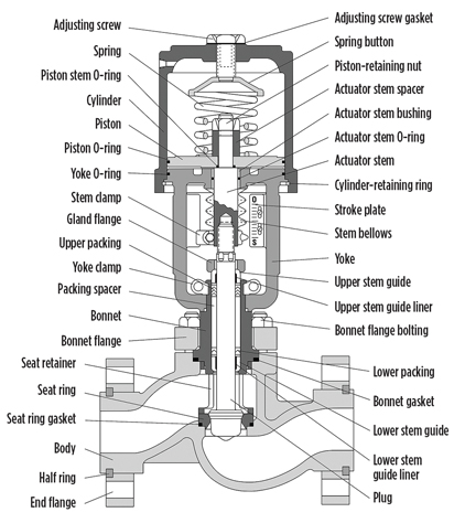
Liquefaction. In the case of LNG, natural gas is taken from a pipeline, or even directly from a producing well, and the CO2 and H2O are removed, typically using molecular sieves. The gases are then compressed. Extensive use is made of cryogenic butterfly, globe-style control (Fig. 5), ball and gate valves to help control the process.
 |
|
Fig. 5. Rising-stem globe-style control valve. Image courtesy of Flowserve Corp. |
During the liquefaction process, the gas passes to a precooler, where its temperature is lowered. It then passes to the cold box, where the gas is cooled further and converted to liquid. Other natural gas liquid components, including ethane, butane, propane and natural gasoline, are drawn off. The LNG, which is pure methane, is sent to storage tanks.
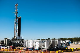
Storage. LNG as a cryogenic liquid is stored in various types of insulated storage tanks (Fig. 6). These tanks are located aboveground or belowground at liquefaction or gasification sites, or used as supply site storage at peakshaving plants, drilling rigs or fueling stations. They are also used in transport tanker trailers for the transportation and delivery of LNG to end users. Valves, including gate, globe and ball types, are used to isolate the fuel before and after loading, and to control and isolate the dispensing systems.
 |
|
Fig. 6. LNG storage tanks. Image courtesy of Encana |
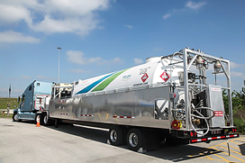
Distribution. After LNG is produced, it is distributed to an end-user location, which can be remote points such as drilling and oil production platforms, fueling stations or marine bunkers. Distribution is typically performed via tanker trucks, whose trailers (Fig. 7) may simply store the LNG or may also be equipped with a vaporizer to gasify and dispense the natural gas. Multiple valves—typically globe, gate and ball types—are used on each tanker, while valve automation is done by either pneumatic or electric actuators to isolate and control loading and unloading.
 |
|
Fig. 7. LNG road tanker. Image courtesy of Encana |
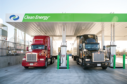
Refueling. Last in the chain of LNG supply for transportation is the refueling station for dispensing the LNG to vehicles or high-horsepower equipment. Valves on refueling stations (Fig. 8) are used to isolate and control LNG flow and are of cryogenic design. Operation is either manual or automatic and normally uses pneumatic actuators. The typical valves used are ball, gate and globe types.
 |
|
Fig. 8. LNG refueling station. Image courtesy of Clean Energy. |
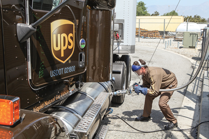
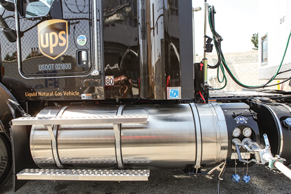
The trend toward LNG as the fuel of choice for trucking in the US is rapidly increasing. Although specially designed to contain the cryogenic LNG, the fuel tanks (Figs. 9 and 10) look similar and provide similar ranges to their diesel counterparts. Non-extended cryogenic valves are used on these tanks for isolation before and after filling. Non-extended valves can be used for intermittent service like a filling operation, where the valve is only subjected to cryogenic liquid for a short period of time.
 |
|
Fig. 9. Filling an LNG tank on a UPS long-haul truck. Image courtesy |
 |
|
Fig. 10. An LNG fuel tank with an equivalent range to a diesel tank. |
Takeaway. Modern extraction techniques are positioned to provide abundant supplies of natural gas at competitive prices. This scenario and other factors are expected to encourage the use of CNG and LNG in transportation and high-horsepower applications, providing a stable, clean source of fuel for years to come. With cryogenic liquid gas, demand for LNG-suitable valve applications is set to grow alongside the expanding LNG fuel market. GP
Literature cited
1US Department of Energy, “Vehicle Technologies Office,” January 31, 2014.
2US Energy Information Administration, Annual Energy Outlook 2012, June 2012.
3US Environmental Protection Agency, National Clean Diesel Campaign, “Verified Technologies List,” January 9, 2014.
 |
Brian P. Hood is the technology manager for ball valves at Flowserve Corp. Mr. Hood is also the co-inventor of the patented Nobleizing process for the hardening of reactive metals. He possesses nearly four decades of experience in the manufacture of valve and pressure-vessel castings in alloys from carbon steel to nickel-base materials. Mr. Hood earned his degree in business from Fullerton College in Fullerton, California, and has completed technical training in metallurgy, foundry practice and valve manufacturing.


Comments