
Optimize small-scale LNG production with modular SMR technology
B. Price and M. Mahaley, Black & Veatch, Overland Park, Kansas; and W. Shimer, UOP, Des Plaines, Illinois
In North America, there is renewed push and demand from end users for cleaner, cheaper, locally supplied fuels for transportation and high-horsepower applications. A number of solutions have been brought forth, each with their own benefits and drawbacks. One technology solution that has seen sustained growth throughout the world is the use of LNG for heavy-duty trucks and high-horsepower (or off-road) uses. Although LNG facilities have been in operation for more than 40 years in the US, the use of LNG for vehicle and off-road applications is in its infancy.
Small-scale LNG: North America. The small-scale LNG industry in the US was initially developed in the 1960s and 1970s, and generally consisted of peakshaving facilities for winter gas supply. Here, “small-scale” is defined as liquefaction plants with single-train capacities of less than 40 million standard cubic feet per day (MMscfd), or 485 thousand gallons per day (Mgpd) of LNG output.
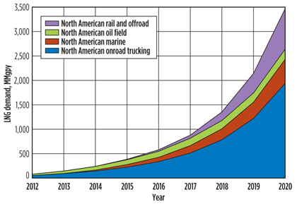
In North America, demand for LNG as a fuel substitute for diesel is projected by Zeus Development Corp. to grow by more than 50%/year (yr) from 2014–2020, reaching 3.5 billion (B) gal/yr (10 MMgpd) of LNG by 2020. Fig. 1 illustrates this projected demand buildup. The vast majority of the LNG production units will be supplied by new, standalone plants and additions to existing gas processing facilities. A few existing peakshaving plants may be modified for LNG net supply, but all will require regulatory approval to modify operations. To fulfill this demand, in excess of 30 new small-scale liquefiers could be required in North America by 2020 for distributed LNG fuel use alone.
 |
|
Fig. 1. North American LNG demand forecast. Image courtesy of |
Small-scale LNG: Rest of world. In several other countries, LNG plants are being developed to supply LNG to remote users and provide clean vehicle fuels. These facilities are growing rapidly in both number and capacity as LNG is adapted to new end uses. One company that has been active in the LNG fuel industry for 10 years has completed 25 such plants globally. This company’s Chinese plants follow a distributed LNG model, where LNG is produced and transported to a number of different users. The schematic in Fig. 2 illustrates this distributed LNG model. With a small-scale LNG plant and trucking facilities, gas can be provided to new customers in both industrial and residential locations. New customers can be added in a short time with a single LNG tank and a small vaporizer.
 |
|
Fig. 2. Distributed LNG model for China. |
This distributed LNG model provides much more flexibility of supply than a traditional pipeline system because the LNG can be sourced from any number of suppliers. In the past five years, the focus in China has shifted to developing clean fuel for transportation applications. At recently built plants, filling stations have been added to provide LNG loading directly to user vehicles, in addition to facilities for LNG tanker loadout. When all of the presently contracted facilities come onstream, the total LNG capacity in China will be more than 9 MMgpd. The average LNG plant size in China has grown to about 33 MMscfd (400 Mgpd).
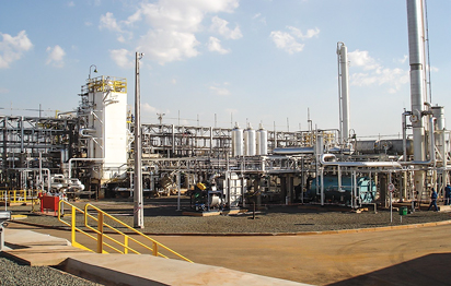
Typical peakshaving LNG plants in the US have liquefaction capacities of 5 MMscfd–20 MMscfd (60 Mgpd–240 Mgpd) and are intended to fill a large LNG tank in 150 to 200 days. These plants are designed to ship large volumes of gas for winter use from tankage at a moment’s notice. One such plant is shown in Fig. 3. This liquefaction plant has a 12-MMscfd (145-Mgpd) liquefaction capacity. Approximately 1.2 billion cubic feet (Bcf) (60,000 m3) of storage is used to hold the LNG until it is ready for use in the winter heating season.
 |
|
Fig. 3. Alabama Gas Co.’s LNG plant in Pinson, Alabama. |
A similar facility was developed in Brazil to produce 14 MMscfd (170 Mgpd) of LNG for use as vehicle fuel (Fig. 4). The LNG is stored in a 6,000-m3 (1.6-MMgal) tank that provides about nine days of storage. The facility is designed to handle six different feedstocks of varying pressure and richness to produce a usable LNG product for vehicles. This plant started operation in 2006 and has been steadily increasing supply of LNG with its first train. A second train is under consideration.
 |
|
Fig. 4. White Martin’s LNG plant in Paulinia, Brazil. |
Within North America, LNG plant capacities of 4 MMscfd–40 MMscfd (50 Mgpd–500 Mgpd) are under evaluation for new greenfield investment. Modular project execution has been embraced by the majority of future LNG owner-operators because of the cost, schedule and reliability advantages offered vs. entirely field-erected liquefaction plants. Finally, a new small-scale greenfield modular single-mixed-refrigerant (SMR) plant in North America is estimated to provide LNG plant owner-operators with a highly competitive, variable production cost, excluding natural gas feedstock, of $0.08/gal to $0.11/gal of LNG.
Technology selection. Three processes are applied to distributed fuels and peakshaving LNG production facilities: methane expansion, nitrogen (N2) refrigeration and SMR. Each of these processes has preferred application areas. Methane expansion plants have been applied in areas where a large quantity of gas is expanded from a high-pressure (HP) pipeline to a low-pressure (LP) pipeline on a daily basis. This pressure differential can be utilized to produce LNG. The N2 refrigeration process has been applied in small projects and on many LNG tankers to recondense boil-off gas. Peakshaving and vehicle fuel applications have been limited because of low efficiency for N2 processes.
The SMR process has been the workhorse of the industry, with an estimated 80% share of installed capacity, and it continues to be the process of choice for most applications. Dual-loop and cascade processes have been applied in the past, but these processes generally are not suitable for these smaller plants because of complexity and capital cost issues.
The expander process is useful when a facility is located where a large volume of gas can be let down from a HP to a LP gas distribution system. The process is often applied with no compression or minimal compression, which helps reduce power requirements. The process works by processing a large volume of feed gas to liquefy about 15%–18% of the feed gas; the balance must go to a LP pipeline. The ratio of feed gas pressure to tail gas pressure drives the process. A ratio of approximately 16:1 to 20:1 (in absolute pressure) is needed for the process to be applied efficiently with little or no compression. Lower pressure ratios drive the process to liquefy less of the feed gas.
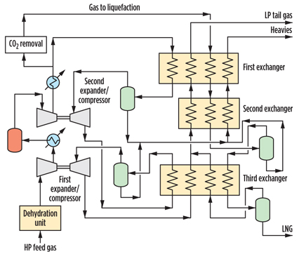
For a 20-MMscfd (240-Mgpd) liquefaction plant, the feed gas rate would be around 140 MMscfd, resulting in a ratio of 7:1 requirement of feed gas to LNG output. A typical expander process, which is a fairly complex setup, is shown in Fig. 5. First, all of the feed gas is dehydrated before it enters the process. Two expander/compressors are then used to boost the pressure of the gas. After compression and cooling, the gas is split into parts. The major portion is expanded and used as refrigerant, and then dumped to the LP tail gas system. The minor portion to be liquefied is sent to a carbon dioxide (CO2)-removal unit and then on to the cold box. The major portion of the feed gas is cooled and expanded in two steps to provide cold streams for liquefying the gas. Controlling the temperatures and pressures in this loop is critical because the gas still contains CO2 and heavy hydrocarbons. Many of the operating problems endemic with these units are in this section of the plant.
 |
|
Fig. 5. Diagram of a typical methane expander process. |
The major benefit of this technology is the reduction in power consumption. For many situations, no compression is required; however, the process has by far the highest capital cost of all the processes because of the complexity of the cycle with multiple expander/compressor systems, multiple exchangers and the need to process a much larger gas stream. Another issue with expander plants is the sensitivity to feed gas pressure and composition. Pressure is related mostly to capacity, but the composition is critical in the cold separators and in the CO2 solidification area. With changing gas markets and a continual increase in peak demand, this process is difficult to utilize in an area where a large quantity of tail gas cannot be handled on a day-to-day basis.
The N2 refrigeration process utilizes N2 as the working fluid to accomplish liquefaction. Using a relatively inert medium is one of the attractive features for this process. Since N2 is a gas that is lighter than the natural gas being liquefied, it is not used as a liquid refrigerant.
The process works by compressing the N2 in a large compressor and then cooling and expanding it in two steps to produce temperatures low enough to liquefy the feed gas. This process has been used for more than 20 years, but it has had limited application recently because of the large amount of power required to circulate the N2. Using N2 as a refrigerant results in a system with about 40% greater energy requirement than a well-designed mixed-refrigerant (MR) system. Since the development of efficient MR cycles, the N2 refrigeration process generally has been applied only on small-scale projects where refrigerant power consumption is not a primary consideration.
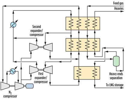
The process uses a large N2 refrigeration compressor and two expander/compressor systems, as shown in Fig. 6. The expander systems are necessary because the N2 refrigerant will not condense in a traditional refrigeration loop setup. To link these systems, multiple heat exchangers (or a complex main exchanger) are required to provide the needed refrigeration for LNG production.
 |
|
Fig. 6. Diagram of an N2 refrigeration process. |
The process also has some difficulty achieving low LNG temperature; all the cooling is sensible heat, so the vapor refrigerant must be generated at a lower temperature than the LNG stream. The greater number of components required for the N2 refrigeration process (expander/compressors) and larger compression increase the cost of the system. The circulation rate for an N2 system will be approximately double that of a MR process. In addition, with more major rotating equipment pieces, lower reliability is expected.
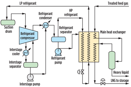
The SMR process is the workhorse of the LNG industry and is used in the vast majority of liquefaction installations. This process depends on a single mixed-refrigerant (SMR) system to perform liquefaction. After treatment, the feed gas is totally liquefied. Only a small amount of flash gas is produced, as the LNG is let down to storage. LNG yields of over 98% are typical, and because the system uses a mixture of refrigerant components and can be tailored to the specific application, it is the most flexible of all the liquefaction systems. As shown in Fig. 7, the final refrigerant separator produces vapor and liquid streams. The liquid flowrate (and, therefore, the vessel holdup) can be changed in the distributed control system.
 |
|
Fig. 7. Diagram of a proprietary SMR process. |
This liquid flowrate combined with a constant HP vapor stream determines the molecular weight of the refrigerant in the main exchanger. Therefore, the refrigerant can easily be adjusted for changes in feed conditions while the plant is in operation. The other liquefaction processes cannot alter the circulating condensing medium (gas or N2); the only adjustment available is flowrate. This ability to adjust to changes in feed gas conditions and composition is the primary reason that mixed-refrigerant systems are more flexible.
The process, as shown in Fig. 7, has a low equipment count, which simplifies operation and minimizes maintenance costs. Since the mixed-refrigerant process has one compression system, it has the highest reliability, in part because the refrigerant pumps are spared. The refrigerant makeup is also minimal during operation and typically represents less than 2% of the plant operating cost.
Process comparison. In Table 1, a techno-economic comparison is shown for the three processes based on electric motor-driven compressors for all services.
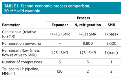
Capital cost. The SMR process typically requires the lowest capital cost. In addition to having only one major piece of rotating equipment, rather than two for the expander process and three for the N2 process, the SMR process is an all-carbon steel system. Since there are no expanders, the only stainless steel metallurgy is in the heavy hydrocarbon-removal and LNG product systems.
The N2 process has a higher upfront cost than SMR, primarily because of its expander/compressor packages, larger refrigerant circulation rate and larger refrigeration compressor. The expander process has the highest capital cost because it requires a larger gas treating system; a more complex exchanger/cold box; significantly greater numbers of cryogenic vessels, valves, etc.; and a larger inlet compressor than the other processes. The costs defined here include inlet dehydration and CO2 removal.
Power cost. Table 1 provides a recent comparison of a 20-MMscfd (240-Mgpd) plant application with electric motor drives.
The SMR process is efficient as measured by power consumption; its power requirement is higher than that for the expander process, assuming that all the tail gas can be dumped to the LP pipeline at all times. If the tail gas cannot be dumped, it would need to be recycled, and recompression would be needed. The N2 process loop has the highest power consumption, as previously discussed. In many cases, the savings in power for the expander process cannot overcome the investment cost difference.
Operating cost. The direct operating costs for the processes are fairly comparable in terms of personnel staffing. The two expander systems require more maintenance than the MR process; each of these units has instrumentation and lube oil systems that require attention. Overall, the SMR process has the lowest operation and maintenance cost of the three processes.
In summary, within North America, the SMR process is anticipated to deliver a variable LNG production cost, excluding natural gas feedstock, of $0.08/gal to $0.11/gal, which reflects a 20% cost advantage compared to N2 expansion.
Safety and reliability. Although the N2 process uses a non-hydrocarbon refrigerant, the other two processes use refrigeration systems that contain the same hydrocarbons as found in the feed gas. Only the relative proportions are different. The expander and SMR processes use a refrigerant that is primarily methane. In the expander process, feed gas with heavy ends removed is used as the refrigerant. In the SMR process, the feed gas is used as makeup, with additions of hydrocarbons normally found in the feed gas in different proportions.
The expander and MR systems have proven reliable and safe for over 30 years. In the US, nearly 90% of liquefaction units are based on the mixed or cascade refrigerant and the expander cycle. Additionally, the SMR process, with only one major compression duty rather than three, will have a reliability edge over the other processes.
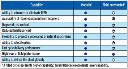
Modularization. Modular fabrication and project execution provide benefits, including an accelerated schedule, a lower installed cost and increased reliability, to small-scale LNG plant owner-operators. The McKinsey Global Institute estimates that, within the oil and gas sector, direct project costs can be reduced by as much as 15%, and project delivery can be expedited by 20% compared to purely field-fabricated projects.
There are a number of reasons why modular projects can offer benefits over field-constructed projects. A common set of proven mechanical equipment is incorporated into the modularized designs to increase reliability. Shop fabrication also uses more specialized, repeatable labor practices that can increase the quality of welding and standardize the layout of equipment. Both practices contribute to a high-quality, consistent, preengineered small-scale LNG plant.
As mentioned previously, the prefabrication and quick installation of modules also saves time and cost compared to field-erected plants. An estimated six-month schedule advantage can be achieved with modular construction. This time savings is achieved by preengineering the key process modules and equipment, avoiding unnecessary customization and preordering the long lead-time equipment, including compressors, heat exchangers and bullet tanks.
Within the North American LNG fuel sector, this six months could be worth up to $12 MM in additional liquefaction revenue, assuming a 70% operating rate for a 16.5-MMscfd (200-Mgpd) facility. Construction of a modular, small-scale LNG facility is also simplified by reducing the need for connective piping and wiring external to pipe skids. The layout of the plant skids is predetermined, which reduces engineering and incremental labor requirements for field construction. Finally, the process modules are checked for quality in the shop to reduce field corrections and startup complexity. Fig. 8 illustrates a comparison of modular and field-constructed project execution.
 |
|
Fig. 8. Comparison of packaged modular vs. field-built process units. |
Modular project execution is already proven within the natural gas industry, as demonstrated by its role in facilitating the rapid development of shale gas reserves within the US. Nearly 100 prefabricated gas treatment and cryogenic NGL recovery plants have been supplied to support the economic recovery of NGL and new supplies of shale gas.
Within the “gas patch,” upstream and midstream plant owner-operators realized the economic value of a fast, flexible and repeatable modular work process. A reduced schedule of up to six months was achieved for specific projects, allowing owner-operators to be first movers in areas such as the Eagle Ford and Marcellus basins. Financial returns and cashflows were enhanced through faster monetization of natural gas and NGL. Finally, modular gas plants have, and continue to provide, the flexibility to adjust for changing gas composition, thereby allowing companies to preorder plants in anticipation of future projects.
A modular execution model fits well for the small-scale LNG fuels sector. The North American LNG fuel industry will demand high-quality, consistent and cost-effective liquefiers that can be replicated across multiple locations and feed gas conditions. A preengineered, repeatable modular solution is, therefore, ideal for owner-operators that are evaluating investment in multiple liquefaction plant locations or phased capacity investments at a single plant location.
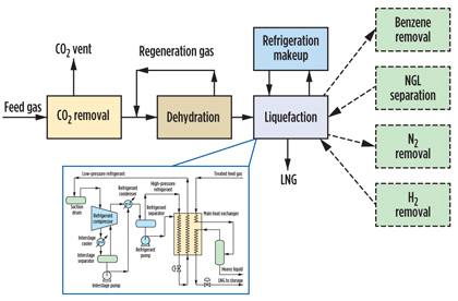
Additionally, to offer flexibility, individual process modules can be added as needed to address different feed gas impurities and end-product requirements. Fig. 9 illustrates how hydrocarbon (benzene, NGL), N2 and hydrogen process modules can be incorporated as add-ons to the core pretreatment and liquefaction modular platform.
 |
|
Fig. 9. Process flow of a proprietary standard SMR plant module. |
The North American transportation and high-horsepower sectors will benefit from the availability of preengineered, full-scope, turnkey liquefaction plants. Owner-operators, particularly those unfamiliar with the operation of liquefaction facilities, will demand both project management and ongoing program management from their plant providers. A North American alliance addresses this need through the supply of a full-scope, small-scale liquefier with lifecycle services spanning from conceptual design to startup to aftermarket support.
A schematic of the inside battery limits processing portion of a 16.5-MMscfd (200-Mgpd) small-scale LNG facility is shown in Fig. 10 to illustrate the modular nature of the liquefier. The schematic does not include tank storage or LNG offloading that would be included as part of a full-scope liquefier.
 |
|
Fig. 10. Schematic of a preengineered modular plant. |
A question remains in the industry as to which preengineered small-scale LNG plant capacity will most competitively position LNG fuel suppliers. To effectively balance capital cost, operating cost and plant capacity loading, an 8-MMscfd–35-MMscfd capacity (100-Mgpd–400-Mgpd) liquefier should be considered, subject to localized demand projections. At 8 MMscfd (100 Mgpd) or greater of LNG capacity, and with a turndown rating of up to 50% for SMR technology, sufficient scale of the key mechanical equipment can be achieved to provide an effective capital cost while maintaining an efficient energy-to-refrigeration conversion.
As LNG demand increases over time within an approximately 300-mile orbital radius from the liquefier, the capacity loading would be expected to ramp up quickly from the initial 50% or greater operating rate. Taking all these factors into consideration, LNG production costs for an SMR liquefier with a capacity of 8 MMscfd–35 MMscfd (100 Mgpd–400 Mgpd) will be significantly lower vs. smaller mini-/nano-sized plants of less than 4 MMscfd (48 Mgpd) of LNG capacity.
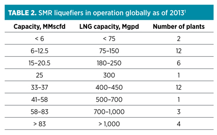
Table 2 displays the number of one company’s proprietary SMR liquefiers in operation globally as of 2013.1 The data indicate that the SMR liquefaction process has been effectively applied to a wide range of plant capacities—from 6 MMscfd–80 MMscfd (75 Mgpd–1,000 Mgpd). The table also indicates a spike of plants in the 6-MMscfd–20.5-MMscfd (75 Mgpd–250 Mgpd) and 33-MMscfd–37-MMscfd (400-Mgpd–450-Mgpd) capacity ranges, particularly as the LNG fuel industry has rapidly developed in China.
In the future, the need for more preengineered liquefiers in North America in the 8-MMscfd–35-MMscfd (100-Mgpd–425-Mgpd) range appears to be the appropriate “sweet spot” to most competitively position LNG fuel producers for the long term. GP
Note
1The proprietary SMR technology is Black & Veatch’s PRICO process.
 |
Brian Price is the LNG advisor for Black & Veatch. Previously, he served as vice president for LNG technology, in charge of technology development and process design for LNG production facilities, LNG import terminals and related gas processing and NGL recovery facilities. Mr. Price has worked for Black & Veatch for the past 20 years. He has over 40 years of experience in gas processing and related technology areas. Prior to joining Black & Veatch, he worked for ARCO Oil and Gas Co. Mr. Price is a member of AIChE and is active in the Gas Processor Suppliers Association (GPSA). He serves as chairman of the editorial review board for the GPSA Engineering Data Book, and previously served as chairman of the technical committee for the Gas Processors Association (GPA). Mr. Price holds BS and MS degrees in chemical engineering from Oklahoma State University.
 |
Martin Mahaley is responsible for business development, strategic planning and commercial analysis for the Transportation LNG project portfolio within Black & Veatch’s oil and gas business unit. Goals for Transportation LNG include expansion of market, focusing on high-horsepower and heavy-duty transportation markets in North America. Mr. Mahaley has been involved in US heavy-duty and freight transportation markets for over 30 years, as both an owner of transportation companies and a provider of value-added transportation products and services.
 |
Will Shimer is a senior strategic marketing manager within UOP’s Gas Processing and Hydrogen Group. He is focused on business development for emerging sectors within the natural gas space, including small-scale LNG. Mr. Shimer has previous experience with Air Products and Chemicals Inc., BP America, and Occidental Chemical Corp. in roles including project and product management, strategy and business management. Mr. Shimer holds a BS degree in chemical engineering from the University of Illinois and an MBA degree from the Harvard Business School.


Comments