
Flexibility is key to FLNG project success
J. Talib, S. D. Hoffart and W. L. Bartel, Black & Veatch Corp., Overland Park, Kansas
Floating liquefaction facilities have a number of advantages over land-based facilities, but they also carry some unique challenges with regard to operational demands and feedstock variability.
A solution to these challenges is Black & Veatch’s PRICO liquefaction technology, which contains the elements required to meet the needs of offshore LNG producers. Operational flexibility—specifically, the ability of PRICO single mixed-refrigerant (SMR) units to handle a wide range of gas pressures, compositions and production rates—provides owners with a wide range of feed gas options and commercial flexibility. Similarly, a low equipment count results in a smaller footprint and lighter weight, both of which are valuable in the offshore market, where footprint is limited and where weight drives costs and schedule.
In addition to these features, the technology can be designed to fit the available utility systems with choices in air or water for interstage cooling, as well as a choice among motor, gas turbine or steam turbine drivers. This flexibility allows the owner to select the best options for its specific application.
The proprietary SMR liquefaction plants have been designed in a wide range of capacities, from 0.1 million tons per year (MMtpy) to 1.5 MMtpy in a single train. When larger production rates or operational flexibility for capacities are required, multiple trains can be used to provide the design that best fits the client’s needs and commercial requirements. The basic flow diagram remains the same for any size of plant.
Another technical challenge when moving a liquefaction technology offshore is the effect of motion and if the equipment can be properly designed for this state. This requires studies examining process operability, mechanical design, safety, construction materials and offshore maintenance.
There are significant opportunities to explore offshore and nearshore LNG opportunities around the world. The proprietary SMR technology for onshore applications can be directly applied to offshore projects, allowing clients to harness extensive capabilities in the LNG production market. This technology has been proven with over two dozen operating plants—and 11 more in detailed design or construction—located around the world. With the upcoming planned commercial operation of the EXMAR floating liquefaction, regasification and storage unit (FLRSU) project in 2015, this SMR process will also become a proven technology for the offshore world.
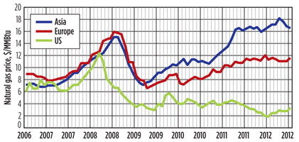
Evolving US energy picture. The US underwent a period of buildout of LNG import terminals in the last decade. This buildout occurred in anticipation of a shortage of domestic gas supply and increasing gas prices. As seen in Fig. 1, gas prices in the 2006–2008 time frame increased from $6/MM British thermal units (MMBtu) to a peak of approximately $12/MMBtu. At these price levels, the import of LNG represented a strong market for gas suppliers.
 |
|
Fig. 1. Natural gas prices, 2006–2012. |
During the 2000–2010 decade, many LNG import terminals were completed in the US, Mexico and Canada to accept new supplies of LNG. However, during the 2008–2010 time period, gas prices fell dramatically as the US economy sagged. Also, large supplies of domestic gas were discovered in a number of US shale plays. At these lower domestic price levels, import of LNG was not an economically viable option.
At the same time, regional high demand for natural gas, particularly in Asia, spurred interest in building LNG liquefaction and export facilities. To take advantage of this demand increase, many owners of US import terminals decided to push forward projects to add liquefaction capacity to existing terminals, and also add capacity to new terminals that were permitted for import but were revised for export. Most of these terminals are slated for large-scale gas supply to Asian and European markets. These larger, onshore, baseload LNG export production plants require significant capital and take 4–5 years to bring online.
A novel floating LNG (FLNG) concept offers a number of advantages over land-based structures, which can be economically attractive. FLNG provides a faster way to build a small- to mid-scale LNG production facility nearshore, in protected waters and/or dockside. The focus on a simple, reliable process solution and barge structure is making this concept a reality for converting US pipeline gas into LNG for export to markets that require smaller LNG volumes than are envisioned with large-scale projects.
Liquefaction technology. The main concerns for a floating facility can be very different from those for a land-based facility. A successful barge-mounted project requires the application of liquefaction technology that is space-efficient, cost-efficient, and energy-efficient.
The SMR process is the workhorse of the small- and mid-scale LNG industry, and it is used in more than 85% of all units in operation. The proprietary SMR technology is used in 25 operating units, and it is proven in a range of LNG project sizes. Other processes, such as nitrogen (N2) refrigeration and expander technology, have been suggested for offshore LNG; however, the loss of efficiency in these processes limits their appeal for actual applications.
The low efficiency not only impacts energy consumption, but also leads to sharply increased deck space requirements and a consequent increase in capital cost. On the other end of the project scale, baseload processes, such as propane mixed-refrigerant (C3-MR) and dual-mixed refrigerant (DMR), have been promoted for scale to FLNG applications. However, the complexity and high capital cost of these processes make them less suitable for smaller FLNG projects. In addition, larger FLNG projects tend to use complex processes with tall, spiral-wound exchangers that may not be suitable in floating environments.
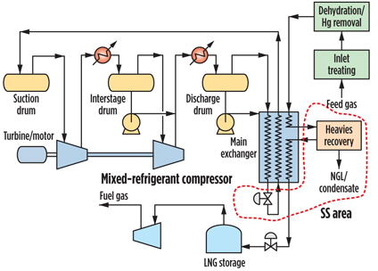
The proprietary SMR process (Fig. 2) is normally the lowest-cost design for small- and mid-scale liquefaction systems due to its low equipment count and flexibility in handling a broad range of feed gases.
 |
|
Fig. 2. PRICO liquefaction process. |
The footprint of a floating structure is a key concern, since every square foot of space is a foot of barge super-structure metal that must be purchased. The low equipment count of an SMR process allows it to fit within tighter space limitations, thereby lowering associated capital costs.
The proprietary SMR technology, in contrast to the other processes discussed, has a single compression system for refrigeration. Also, the main exchanger is a simple plate-fin unit with a minimal number of connections. This setup results in a low-cost and easy-to-operate liquefaction process. The system is designed so that, during a shutdown, the refrigerant inventory is maintained in the system. No venting or pressure relief is needed, and an advanced refrigerant recovery system eliminates losses to the main compression seal gas system. This type of process has become the workhorse of the small- and mid-scale LNG industry around the world, and is well suited for offshore FLNG applications.
Improvements in the proprietary SMR process over the years have resulted in a 25%–35% reduction in power vs. older facilities. Generally, these processes require about 260 kilowatts (kW)–370 kW per million standard cubic feet (MMscfd) of LNG capacity. The exact value depends on the system design parameters, such as feed gas pressure, ambient conditions and process specifications.
The main exchanger, a key piece of equipment in the liquefaction system, is an aluminum plate-fin core assembly housed in a carbon steel box. The box is filled with perlite for insulation. All connections are external to the box, which eliminates any leak potential inside the box. This design has been proven to be effective in providing long-life facilities that need no maintenance. Several installations are approaching 40 years of operation without the opening of the main exchanger.
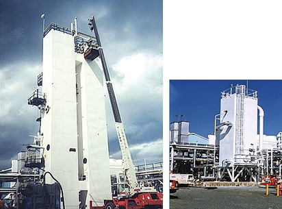
Modern SMR plants have much more efficient main exchanger designs than do the more complex facilities using spiral-wound exchangers. Fig. 3 shows a facility where a 1970 vintage spiral-wound unit was replaced with a modern plate-fin unit that is one-third the size and half the cost. The compact size and lower weight are key features as the process is considered for offshore.
 |
|
Fig. 3. Main exchanger comparison. |
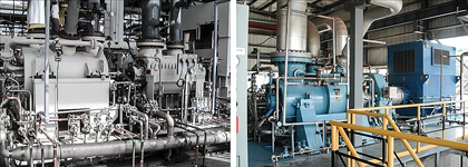
Another critical item in an LNG process is the refrigeration compressor. A simple, repeatable design using a single-body, two-section unit is favored. This compressor can be purchased in a wide range of sizes from 5 MW to over 100,000 MW. Fig. 4 shows an MR compressor for a PRICO plant.
 |
|
Fig. 4. Refrigerant compressor comparison; two-body compressor (left) |
Being a barrel-style unit, the bundle can be pulled without disconnecting the overhead piping. This is also an economical design compared with other systems, such as those used with spiral-wound units. This configuration provides a compressor that is easier to maintain than the multiple-body units required in more complex processes. In these other processes, the refrigeration loop requires a barrel-style unit and a horizontally split compressor. This configuration results in a more expensive unit, and it is more difficult to provide maintenance for the horizontally split unit.
Feed gas flexibility. One of the challenges for LNG production facilities is that many locations are served by multiple pipelines. While these supply lines have generalized tariff specifications, they lack the detailed specification by gas component that is normally desired by plant designers. Therefore, the feed gas composition can vary widely, especially in the mid-range hydrocarbons (C2–C4), which impacts the outlet LNG heating value content. Also, the heavier C5+ components can vary widely across gas supply options. These components must be removed to protect the facility from solids formation. Inert gases, such as carbon dioxide (CO2) and N2, should also be considered.
One of the significant advantages of a floating facility is that it can move from location to location as the economics or resources change. To make the best use of this advantage, the liquefaction technology is required to be flexible enough to handle a wide range of feed gas qualities and operating conditions. In addition, the technology must be able to operate offshore under conditions in which the forces induced by wave motion can cause process upsets or mechanical failures.
The SMR process has been used successfully in many applications with varying feed gas compositions and pressures. In 2005, the first LNG production facility to use the proprietary SMR technology was started up in Brazil. It has a wide possible composition range to be processed, in addition to a fairly wide range of possible feed gas pressure (450 psig to 1,000 psig).
The process was designed so that any of these feeds and pressure combinations could be processed without plant shutdowns or severe intervention. All process adjustments can be handled in the computer control system (Fig. 5). The refrigerant composition can be varied with the adjustment of the high-pressure refrigerant liquid (HPRL) flow from the refrigerant outlet drum to the main exchanger. This variation is accomplished in the distributed control system (DCS) with a single valve adjustment.
 |
|
Fig. 5. Process control flow. |
In addition, the refrigerant flow through the main exchanger is controlled with the Joule-Thomson (JT) valve at the bottom of the plate-fin unit. The DCS is configured to sense and adjust the flow with changing load on the system. Therefore, the proprietary SMR system can be adjusted for abrupt or long-term changes in feed gas with only internal valve adjustments; no input or withdrawal of refrigerant is required. With larger units involving multiple core assemblies in the main exchanger, each core has a JT valve to control the refrigerant flow through the core. In this way, the process is always under complete control by the operator at the core level, again with the DCS system.
CO2 is normally limited to 2% or 3% in these feed gases by pipeline specifications. The true gas analysis is often 1%–2%. However, since the CO2 is allowed to be higher, normal design is based on 3%. The system is designed to be turned down to handle the lower value with savings in utilities. N2 can also vary with the supply gas tariff. Normally, N2 is present in fractional percentages, but it can be present at up to 3%.
The N2 has little impact on the liquefaction operation, but some portion of the N2 will end up in the LNG. During LNG handling, the majority of the N2 ends up in the fuel gas stream. Most of the large turbines used in the SMR process can handle N2 content up to 40%. Therefore, the N2 exits the process in the turbine exhaust. In other plants that have higher N2 content, multiple process configurations can be used to reduce the N2 to acceptable levels, using separation technologies.
The Jilin Songyan Qianyuan Energy LNG project in China, which is scheduled to start up in 2014, is designed to process feed gas containing up to 6% N2, while meeting a specification of less than 1% N2 in the LNG product. This plant has also been designed for operational flexibility and can process gas ranging from 200 psig–1,000 psig without the need for inlet compression.
Process flexibility. A desired application for FLNG is to reach and process stranded gas. Traditional land-based plants are unable to process this gas due to economic or physical limitations. FLNG provides a way to economically process this gas that would otherwise be unusable. This gas may come from unconventional sources and require a liquefaction technology that can meet different process applications to effectively process it.
The SMR process can be tailored for applications other than typical pipeline gas liquefaction. In January 2014, the Wuhai Xilaifeng LNG plant began producing an LNG product stream using synthetic natural gas (SNG) as the feed gas from an upstream coking gas methanation process. The excess N2 and hydrogen (H2) contained in the feed (up to 20% H2 and 10% N2 of the incoming SNG) is removed, while the purified LNG is directed to an LNG storage tank. The plant is designed to process 1.3 MM Nm3/day of SNG into 0.25 MMtpy of LNG.
Another example is the Xinjiang Guanghui methane separation plant, started up in 2013, which is designed to take a feed gas stream from a coal gasification plant containing CO, H2 and methane. The CO/H2 are separated into one stream and sent downstream for methanol synthesis, while the methane is liquefied into LNG for commercial sale. This plant uses two trains to process 10.86 MM Nm3/day of feed gas into 0.5 MMtpy of LNG and 9.21 MM Nm3/day of SNG. The large compressors in this plant use steam turbine drivers, which utilize the excess steam produced from the gasification plant while reducing fuel gas usage and power requirements within the liquefaction unit. The refrigeration requirements for SNG separation and LNG production are provided by the SMR system.
Process capacity. LNG technologies require a process that can be designed for a wide range of production capacities to meet various applications; this is especially true for FLNG applications. Depending on the location and economics, it may be desirable to have a small-, mid- or large-scale processing facility.
Due to shifts in the LNG market, many import terminals have LNG inventory in their tanks but are not actively importing. The heat leak into the tank boils off the LNG inventory and, many times, must be flared or sent to an outside battery limits pipeline. This lost LNG must be replaced to keep the tanks cold and maintain required LNG specifications. Many owners are now considering the installation of boil-off gas (BOG) reliquefaction facilities to limit inventory losses and reduce subsequent operating costs. SMR technology has been proven to provide operational simplicity for these small-scale plants, while maintaining high efficiencies and low operating costs. The Cameron LNG BOG liquefaction project, started up in 2013, was designed for this purpose and successfully operates at a capacity of less than 0.1 MMtpy.
High energy demand in China has necessitated the construction of many small- to mid-scale LNG facilities. The SMR process has become a common choice for these applications. The low capital cost and small footprint result in a reduced time to market and allow these plants to be started up in around 20 months from project kickoff. Within the past year, plants have come online in China in Bazhou, Wuhai, Xingyuan and Yuanheng. These plants are designed to produce between 0.25 MMtpy and 0.39 MMtpy of LNG. The Bazhou plant is tailored to supply LNG to Beijing, to provide a clean form of energy for the city’s public transportation systems.
SMR technology is also an attractive option for large-scale plants. Multiple trains can be used to attain the desired LNG production rate. The Jordan Cove LNG plant is presently in the design phase, with an estimated startup date of 2018. This plant utilizes two gas treating trains and four liquefaction trains. Each liquefaction train is designed to produce approximately 1.5 MMtpy of LNG, for a total plant capacity of 6 MMtpy. The facility also includes an onsite power plant that is heat-integrated with the process. This arrangement further increases overall facility efficiency.
Dividing a plant this size into multiple trains has many advantages. With four trains in operation, there is less production loss with a single mechanical failure. If a train is forced to shut down, production will only decrease by 25%, as opposed to 100% with only one train. Also, dividing the plant into multiple trains results in smaller liquefaction modules. This segmentation is especially beneficial for offshore applications where space is limited.
Offshore configurations. Several factors dictate offshore layout configurations. The simplicity, flexibility and scalability of the SMR process can provide a wide range of liquefaction capacities in single- or multiple-train configurations. Several system options exist from which any configuration can be built around, depending on the location, power availability, permitting constraints for use of water cooling, and the LNG offloading/export strategy. The offshore facility can be self-sufficient, or it can use systems located onshore at dockside for nearshore applications.
Table 1 lists some of the basic systems and the available options. The main refrigeration compressor driver can be a gas turbine or an electric motor. Each option has benefits and is normally selected based on the site configuration. The main process cooling can be accomplished with either water cooling or aerial cooling.
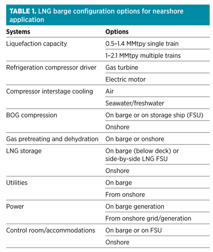
Another option to be considered is the LNG storage. LNG tanks can be located in the vessel for loadout to tankers periodically. Another option is to use a full-size LNG tanker for LNG storage. This tanker would be berthed nearby and would accept LNG production from the facility. The LNG can then be loaded to another tanker, or the tanker being used for storage can be switched out with an empty tanker and taken to the final delivery point.
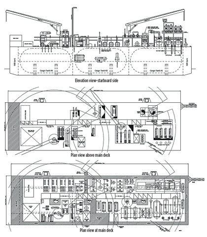
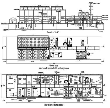
For LNG barge applications, many conceptual configurations have been developed in single and multiple SMR liquefaction trains. Two of these configurations have been advanced through the front-end engineering and design (FEED) stage. These plants use a turbine-driven refrigeration compressor with water cooling. Also included is a power-generation block to provide power for the entire barge so that the barge does not need to depend on an external power supply. A motor drive plant with aerial cooling has been considered, along with the use of turbine waste heat for a gas treatment unit.
Figs. 6 and 7 show general arrangements for the two options. In both the turbine/water and motor/air designs, a similar-size barge can be used for the liquefaction facility. Also, these choices can be made with or without onboard LNG storage. However, onboard LNG storage is provided for storing LNG temporarily in standard pressurized LNG vessels for the changeout of adjacent floating storage units (FSUs) or LNG carriers (LNGCs). This storage could also be located onshore for dockside application in horizontal vessels or vertical storage tanks.
 |
|
Fig. 6. Example barge layout with gas turbine and water cooling. |
 |
|
Fig. 7. Example of a barge layout with an electric motor drive and aerial cooling. |
The volume of these onboard storage vessels would increase with higher capacity for LNG production on barge and greater offtake volume for export. Larger storage requirements would require locating the LNG storage onshore, or in an alongside FSU, specifically for barge LNG production capacities exceeding 1.5 MMtpy. At these large storage requirements, a hull LNG membrane containment system is also an option, although this would impact the advantages of simpler barge LNG production units.
Offshore project applications. The EXMAR FLRSU project, a 0.5-MMtpy PRICO facility using a gas turbine driver that is under construction, will be the first operating offshore LNG production unit in the world. The LNG produced from the topsides is sent to below-deck storage vessels, which are then offloaded to an LNGC. On a larger scale, the Excelerate LNG project, located in Lavaca Bay, Texas, includes an onshore gas treating unit with liquefaction, storage and offloading facilities on a nearshore floating storage, liquefaction and offloading (FLSO) vessel, with four proprietary SMR trains producing more than 4 MMtpy of LNG.
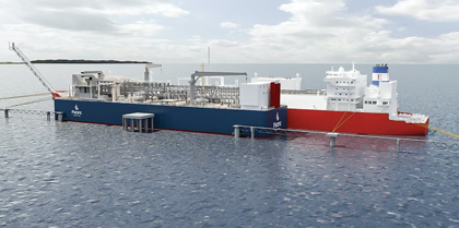
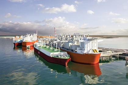
Exmar FLRSU, Colombia. The first turbine/water design has been moved from FEED to final design and fabrication for Exmar’s FLRSU project in Columbia. This barge will be located offshore Colombia, South America, and will provide LNG to local users in the Caribbean market. Fig. 8 shows the Exmar project concept as it is being developed in detailed design. The barge will process 72 MMscfd of gas coming in at 77 bar pressure to produce 0.5 MMtpy of LNG product. The topsides process facility will handle the feed gas stream to remove the CO2 and water in the gas treating and dehydration units.
 |
|
Fig. 8. Exmar FLRSU barge. Photo courtesy of Exmar and Pacific Rubiales. |
The LNG will be sent to onboard storage tanks sized for 16 thousand cubic meters (Mcm) of LNG in three tanks. The barge is designed to continuously load a 160,000-Mcm LNGC via an FSU moored alongside it. The longer-term plan is to load out a 10,000-Mcm LNG tanker for transport to clients in the Caribbean market. The process facility is designed and built in accordance with marine classification requirements to handle the flash gas and BOG from storage and loading. All low-pressure gas will be used for fuel or recondensed to make LNG. A portion of the fuel will be used for onboard power generation. Engine-driven generators in a 3 ! 50% configuration will provide reliable power for the barge operation. All other utilities and makeup systems will be located on the barge, making the vessel self-sufficient. The target date for startup of the project is the first quarter of 2015, representing the world’s first modern FLNG application to come onstream.
Excelerate Energy FLSO, Texas. Another turbine/water design takes a different approach. Excelerate Energy’s project in Lavaca Bay, Texas splits the processing between shore-based and a floating facility. The project (Fig. 9) is designed to produce 4.4 MMtpy of LNG in phase 1, with the gas treating unit, condensate storage tank, cooling water towers and electrical generation based onshore, and the FLSO structure permanently moored nearby.
 |
|
Fig. 9. Excelerate Energy’s Port Lavaca Bay FLSO. Photo courtesy of |
Locating the gas treating and cooling towers onshore allows for extra capacity to be liquefied aboard the FLSO, while having enough space within the same vessel to store 250 Mcm of LNG. Both the onshore and FLSO facilities include their own power generation, so there is no dependence on the local power grid.
A significant driver for the project is the availability of pipeline-quality natural gas. Through extensive analysis of the surrounding pipeline network, multiple nearby pipelines that could feed the liquefaction site were identified. The project presently has the flexibility to pull feed gas from up to nine of these pipelines through a proposed, 29.5-mile pipeline header system that is designed to feed the main processing site. The project is awaiting final Federal Energy Regulatory Commission approval for construction.
Takeaway. The focus on a simple liquefaction technology solution is making offshore projects a reality in the LNG supply market. The PRICO SMR process offers a progressive solution for small- to mid-scale offshore or nearshore LNG facilities. Advantages of the process include its simplicity, flexibility, cost-effectiveness and shorter schedule for producing LNG. GP
 |
Javid Talib has 40 years of domestic and international project engineering and project management experience in the gas, oil and chemical industries, including both onshore and offshore projects. He has been involved in LNG liquefaction projects since 1998 at Black & Veatch, where he is a vice president and the FLNG program manager in the company’s oil and gas business line. Mr. Talib’s 12 years of offshore experience include ONGC’s Bombay High offshore development. He has also worked with Hyundai Heavy Industries for five years, including three years in the company’s shipyard in Korea. He holds an MS degree in engineering from the Indian Institute of Technology in Mumbai, and an MBA degree from the University of Kansas. Mr. Talib is a registered professional engineer in Kansas, and he has submitted and presented several technical papers at many conferences, including the Offshore Technology Conference.
 |
Shawn D. Hoffart is vice president of LNG technology for Black & Veatch Corp. in Overland Park, Kansas. He was previously the LNG section head in the oil and gas division at Black & Veatch. He is an expert in LNG process design and has served as the design lead on numerous liquefaction facilities in the US and internationally. Mr. Hoffart joined Black & Veatch in 1991. Previously, he worked in product development for Goodyear Tire and Rubber Co.’s industrial products division. Mr. Hoffart is a licensed professional engineer in Nebraska. He holds a BS degree in chemical engineering from the University of Nebraska and an MS degree in engineering management from the University of Kansas.
 |
Will L. Bartel is a process engineer for the oil and gas division of Black & Veatch Corp. in Overland Park, Kansas. He is an expert in LNG process design and has served as the startup lead for multiple startups of LNG facilities in the US and internationally. Mr. Bartel joined Black & Veatch in 2009. He holds a BS degree in chemical engineering from Kansas State University.


Comments