
Choose optimal feed conditioning strategies for gas processing
D. B. ENGEL and M. H. SHEILAN, Sulphur Experts, Kemah, Texas
Contamination ingression into gas processing units is one of the most prevalent modes negatively affecting plant operations. To enable plants to run with minimal instabilities, increased capacity and high reliability, it is necessary to condition the feed gas prior to processing by removing unwanted contaminants.
Feed conditioning strategies
Feed conditioning can be achieved using a number of strategies combining mechanical, physical and chemical options. From a mechanical perspective, inlet coalescer systems are key gas conditioning devices in gas processing. They are the last lines of defense against contamination and its associated downstream effects. These systems are considered enabling technologies to allow plants to run near capacity, with low operational costs.
Among the most important functions of inlet separators are the protection of amine plants, molecular sieve beds, compressor inlets and outlets, glycol plants, carbon beds and burners. Fundamental differences exist among the various feed conditioning strategies, systems and devices in terms of their applicability, operability and performance. These directly impact efficiency and effectiveness of contaminant removal—in particular, the difficult-to-separate sub-micron liquids in the form of stable aerosols commonly found in gas streams.
As feed conditioning arrangements are evaluated and inlet separation devices are improved, several different strategies have been successfully identified for ensuring that the feed gas meets processing parameters. These strategies can range from carefully considering feed contaminants, process conditions and variations, to determining correct vessel design and internals. The effects of poor gas feed conditioning can have profound impacts in almost every gas processing operation, such as financial losses associated with low efficiency, extended downtimes, unscheduled maintenance, solvent losses, solvent contamination and degradation, bed deactivation and equipment failures.
Options are available to virtually eliminate feed gas problems that can plague day-to-day or long-term plant operations; several of these options are discussed here.
Gas processing and contamination control
Inlet gas separation upstream of processing units is far more common for gas streams than it is for liquid streams because of its prevalent and diversified contamination profiles. Similarly, inlet separation is far more common in gas processing operations than it is in refinery activities.
Inlet gas separation is usually conducted through the use of a knockout drum equipped with a demister section, using a mesh pad or a vane pack. Some plants use horizontal filter-separators with a vane, or cyclonic elements or stages. All of these systems are not entirely adequate for effective inlet contaminant removal from sour gas feeds. These systems are typically designed for bulk liquids removal and large aerosol droplet sizes. In addition, none of these devices is really designed for solids separation (usually done by a wet scrubber or a particle filter).
With the exception of cyclonic systems and some filter separators that can remove certain solid particles and some liquid-like solids, most contaminants enter the gas processing units untouched. Only a small number of plants have the necessary means to adequately condition sour gas for processing because of the diverse nature of its contaminants. The most difficult and challenging contaminants in any gas stream are small aerosols. These are finely divided liquid particles with diameters ranging from a few hundred microns to less than 0.1 micron.
The basic reason for this inefficiency is directly related to the aerosol droplet size distribution and the flow pattern geometry inside the separator vessel. In other words, the separation media is not capable of separating small liquid droplets. Most aerosols travel intact across the vessel without being separated from the main gas stream.
The vessel design is also fundamental. In some instances, the separation media could be appropriate; however, if the liquids removal from the vessel or the internal flow pattern is deficient, then the vessel will experience a considerable decrease in efficiency. Additionally, some defective vessel designs may actually shatter and disperse liquids, manifested as much smaller droplet sizes in the gas stream, adding difficulty to the separation process.
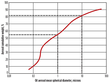
The aerosol contaminant distribution in a gas stream is primarily in the sub-micron range. Larger droplets tend to not be as persistent in the gas stream since the larger droplets are more likely to gravitationally separate. Larger droplets are also more likely to shatter as a result of the shear forces applied to the droplet surface. When large droplets shatter, they create progressively smaller droplets until the distribution is stabilized by the balance between surface energy, gravitational settling and shear forces. The distribution of a persistent aerosol in a gas stream can be as much as 50% by weight smaller than 1 micron, and nearly 80% by weight smaller than 10 microns (Fig. 1).
 |
|
Fig. 1. Typical liquid aerosol size distribution at the outlet of a compressed gas stream. |
Devices (Fig. 2), such as demisters equipped with vane packs, mesh pads, low-performance coalescers and cyclones, are relatively ineffective at capturing the most penetrating aerosols (0.1 micron to 1 micron). In some instances, these devices are also unable to properly separate the aerosols that they capture because of the lack of coalescing power, or due to flooding of the element. Mesh pads do not have the fiber size or density to interact with small aerosols. Vane packs are ineffective since they form an interface layer at certain points, and small aerosols cannot effectively contact the metal surface.
 |
|
Fig. 2. Knitted mesh mist pad (left) and vane pack mist elimination device (right). |
In addition, the small momentum of the aerosols contributes to the inefficiency. Both mesh pads and vane packs have somewhat small operating windows and are prone to fouling and loading. These inefficiencies are also seen in many other systems that use poor coalescing elements, incorrect media and materials selection, and deficient vessels from the standpoints of design, instrumentation, operation and maintenance.
Today, the technology of choice for high-efficiency removal of sub-micron aerosols that negatively plague gas streams in gas processing operations is a coalescing device using microfiber media materials (known as a microfiber sub-micron coalescer, or MSC). These devices can effectively interact with small aerosol liquid droplets. If the coalescer element is built correctly, the intercepted liquid will be effectively coalesced and drained quickly from the element, avoiding flooding and further liquids re-entrainment. Note: Many fabricators advertise systems capable of removing sub-micron liquid aerosols. Most do not correlate these claims and expectations with actual performance. Only a small number of companies possess the proper technology to supply MSC systems.
Recommendations for sour gas conditioning
A typical inlet separation setup usually comprises a large-capacity vessel for bulk liquids removal. This will also act as a slug catcher. These vessels sometimes can be equipped with a mesh pad or vane pack for liquids coalescing. These devices are almost always required and should not be avoided; however, these should be used only for bulk liquids removal. Downstream of these systems, there has to be another MSC separator. This system is equipped with specially formulated microfiber coalescing media that has the ability to intercept and coalesce sub-micron aerosols, and to drain liquids effectively. Sub-micron liquid particles comprise more than 50% of the total liquids contaminant species in a gas stream.
For effective liquid coalescence in a gas stream, the system must perform efficiently in each of the three events taking place in these systems: liquids interception, liquids coalescence and liquids discharge. Fig. 3 illustrates the sequence of events occurring inside a liquid coalescer vessel.
 |
|
Fig. 3. Illustration of liquid coalescence: droplet interception, droplet coalescence and liquid drainage. |
MSC devices (Fig. 4) are carefully designed based on the flow, pressure and temperature (both operation and design) and must be installed as close as possible to the equipment or process that requires protection. The typical design of an MSC will have the capability of removing, on average, a minimum of 99.9% of aerosols between 0.1 micron and 1.0 micron in diameter. This is virtually most of the liquid aerosol contamination in a gas stream. These systems can be protected with an upstream particle gas filter (equipped with the proper separation media) to extend the online life of the coalescer elements and minimize operational costs, as the replacement separation elements for particle filtration are substantially less expensive than coalescing elements.
 |
|
Fig. 4. Liquid/gas coalescer installed (A), and in drawing form (B). |
MSC vessels have two stages. The best system designs have the inlet on the bottom section, which is designed to remove larger liquid aerosols and some limited bulk liquids. The upper section is where the efficient sub-micron separation takes place. The bottom section is sometimes fitted with a mesh pad, vane pack or cyclonic elements. None of these elements has been properly proven to enhance efficiency. In fact, some of these are detrimental for the vessel operation. Both sections must be fitted with a liquids level visualization, controls and drain valves.
The gas then leaves the bottom chamber, flowing immediately above into the second stage via the coalescing elements (inside-to-outside flow). This is where the gas is passed through the formulated microfiber coalescing media. The fine aerosol liquids are intercepted, coalesced and finally drained from the elements by gravity. The purified dry gas then exits from the top of the vessel.
Note: Key considerations are required when designing the drain and level control systems to ensure that the elements remain clear of liquid, whereby saturation of the elements would render them ineffective for properly removing liquids from the element and vessel interior. Even the best coalescing devices are rendered ineffective if the instrumentation and control schemes are not functioning well.
Figs. 5 and 6 illustrate the fundamental importance of proper inlet contaminant separation in feed gas streams. The images show a gas plant in the Middle East that was unable to process the majority of the sour gas because of absorber foaming. This led to high H2S concentrations in the treated gas (making it unable to meet the required 4 ppm H2S specification). As can be seen in Fig. 5, the plant was forced to flare gas, causing emissions and considerable loss of revenues. Fig. 6 shows the same plant a few months later, after a proper inlet separation system had been installed.
 |
|
Fig. 5. Plant flare before coalescer installation.
|
 |
|
Fig. 6. Plant flare after coalescer installation. |
Inlet gas contamination
Proper gas inlet contamination control prior to any gas processing is essential for plant stability, performance and low operational costs. Control is often achieved when there is thorough understanding of virtually all inlet feed contaminants in the gas stream, and the information is taken into consideration when determining what separation process and system are used. Inlet contamination in gas processing can vary drastically and depends on a number of factors, including the following:
- Geographical location and geological formation
- Gas exploration and production operations and equipment types
- Chemical additives use (type and dosage)
- Contaminant types and concentrations.
Aside from heavy hydrocarbons and acid gases [e.g., hydrogen sulfide (H2S) and carbon dioxide (CO2)], feed streams can contain other sulfur-bearing species (e.g., carbonyl sulfide, carbon disulfide, thiol, etc.) and many other contaminants. The most common contaminants are outlined below, indicating their likely origins and process impacts.
Asphaltenes. These are macromolecules [i.e., molecules with high molecular mass of 400 kilograms per kilomole (kg/kmol)–1,500 kg/kmol] that are native to crude oil (Fig. 7). Asphaltenes can be crystalline or an amorphous gel, depending on the exact structure and process conditions. They can contain a number of different metals, such as vanadium, nickel and iron. They can also contain organic components such as thiophene, benzothiophene and other cyclic sulfur-containing species, aromatic rings, long aliphatic chains and any functional groups.
 |
|
Fig. 7. Heptane-soluble asphaltenes (left) and proposed possible molecular structure (right). |
Due to their poor solubility properties in some hydrocarbons, asphaltenes can be present as solid particles and can assist in foam and emulsion formation in amine units or glycol units. Asphaltenes also have been known to retrograde condense in downstream process units, such as desiccant dehydration towers. They are also responsible for valve plugging in absorbers.
The presence of these components can be eliminated by filtration, solvent treatment (solubilizing asphaltenes) or chemical additives (modifiers known as dispersants). These additives change the surface of the asphaltene molecule in such a way that agglomeration of the particles does not occur and solids are minimized.
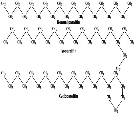
Waxes. These are usually solid crystalline deposits, soluble in crude oil and other hydrocarbon streams (Fig. 8). They can have carbon linear alkane chains or cyclic component chains varying from C18 to C65 (Fig. 9). Waxes are native components in some gas streams and can have a more pronounced impact as a result of temperature and pressure variations in the gas stream.
 |
|
Fig. 8. Paraffin waxes removed from an inlet separator.
|
 |
|
Fig. 9. Schematic structure of typical waxes. |
As with asphaltenes, waxes are prone to depositing in many locations within a process unit, disrupting proper flow hydraulics in absorbers and regenerators, heat exchangers, valves and flash drums. Separation of these components is fairly difficult. Filtration using specialized media is essential for wax separation. Care must be taken for certain gelatinous waxes. Other options are the use of upstream cold sections to condense and sometimes solidify the waxes.
Water. Sour gas streams containing water are far more corrosive than their dry versions. This corrosion is caused by the hydrolysis or dissociation of acid gases in water. Gas streams are normally saturated with water vapor at the hotter wellhead conditions, so water is a constant contaminant in the production and processing of sour gas streams as the gas stream cools during pipeline transportation.
Some water and produced water streams can contain high salts concentration (i.e., brine, hardness, etc.), causing not only gas processing unit contamination, but also compressor failures by solids accumulation and gasket degradation. Therefore, inlet separation must minimize liquid water breakthrough because it is important to keep fouling and corrosive components out of gas processing unit systems. This process is carried out with the use of a horizontal two- or three-stage phase-separation vessel with proper design and fabrication.
Oxygen. The presence of oxygen (O2) causes the formation of heat-stable salts and oxidation products of gas processing solvents. Heat-stable salts are salts that do not regenerate under normal process conditions in amine units, causing a decrease in the unit’s efficiency and enhancing corrosion rates. O2 also causes oxidation of amine molecules, degrading the amine solvent by breaking apart the original molecular structure and, therefore, generating a number of contaminants.
Many of these contaminants can also cause foaming. It is always better to remove O2 at the source. O2 is a very reactive gas, so it has usually reacted with a number of components prior to entering an amine or glycol system. However, even the presence of 1 ppmv or 2 ppmv of O2 is enough to form a considerable volume of heat-stable salts and oxidation products in amine solutions. Many operators ask, “How much O2 is too much O2?” The correct answer is, “Anything more than 0 ppmv.”
O2 must not be allowed to enter an amine or glycol process. A number of upstream systems can cause O2 ingression (primarily associated with vapor-recovery systems in oil production facilities). Possible alternatives are O2 scavenger beds or O2 scavenging chemical additives. O2 will not be removed in a typical inlet separation device.
Mercury. This is a highly toxic, bio-accumulative heavy metal. It interacts with certain metals, causing amalgamation and leading to catastrophic equipment failures. The deleterious effects of elemental metallic mercury (liquid) are most prevalent in liquefaction plants utilizing braised aluminum heat exchangers; however, many gas feeds can have mercury contaminants.
Due to the extreme cold temperatures in liquefaction processes, aluminum is the preferred exchanger metallurgy because it is not as brittle as steel. Separation in gas streams is accomplished by solid scrubber beds and impregnated solid state beds. These can be activated carbon or zeolites impregnated with sulfur components. These impregnated materials react with certain mercury forms, resulting in the formation of mercury salts within the bed. One caution prior to installing any mercury-removal technology is to consider mercury disposal after it has been separated. Also, it is recommended to thoroughly and rigorously characterize the mercury contaminants to be separated, as not all mercury contamination is elemental mercury. Mercury contamination, in general, falls into the following categories:
- Elemental liquids mercury
- Mercury ions (water-based)
- Solid mercury salts and/or oxides
- Organo-mercury (gas-phase) species.
All of these mercury contamination forms require different removal strategies and methods.
Sulfur (elemental). This acts as an oxidizer and degrades amines, similar to the effect of O2 contamination. Elemental sulfur is highly corrosive if found in circulating amine systems. It is difficult to remove with filtration because of the large mass that can accumulate in the filters (demanding specialized filters to accommodate large mass quantities).
In principle, cyclone devices can also be instrumental in removing elemental sulfur. Elemental sulfur can lead to significant corrosion in hot areas of the system, such as reboilers. A big problem with elemental sulfur ingress is that it is difficult to detect because it tends to enter in discrete batches rather than as a steady component of the feedstream. Millipore filtration (using a 0.45-micron inert membrane) is the prime source of detection of elemental sulfur. These filter membranes can be clean and clear in one test and then completely full of elemental sulfur only half an hour later.
Ammonia (NH3). Ammonia is soluble in amine solutions, so the presence of any ammonia in the feedstream will result in significant quantities of ammonia in the rich amine, which concentrates in the regenerator reflux loop, causing enhanced regenerator corrosion and problems with solids deposition. Ammonia is an inorganic nitrogen base and will react with both H2S and CO2 to form ammonium salts that will precipitate at relatively cool temperatures in reflux condensers, pressure and flow-control valves, and even in the downstream sulfur-recovery unit (waste-heat boiler tubes, for instance).
Ammonia ingress is prevalent in refinery operations, but rare in natural gas treating. Refiners usually purge the reflux loop continually to mitigate the effects of ammonia buildup in the reflux loop. Natural gas plants do not generally have to perform any system remediation for ammonia removal.
Methanol. This component is used all over the world as a hydrate inhibitor and a co-solvent for chemical additives for low-temperature use. Methanol is often over-injected because operators would rather be safe than sorry. Hence, significant methanol quantities can enter with feed gases and liquids. Methanol can have a large impact on the performance of inlet separation devices because it is a co-solvent, and both hydrocarbon and water-soluble contaminants could be transported into the separation devices, possibly destroying their efficiency.
Methanol also dissolves in amine and is usually flashed in the regenerator, causing regenerator foam-like conditions or liquid carryover due to the violent flashing at the conditions at the top of the regenerator. Methanol may also concentrate in the reflux loop, which could result in regenerator instability. The best method for methanol removal is to minimize its use upstream in combination with a washwater injection point upstream of an MSC device.
Salts. These can be primarily calcium and sodium chlorides, and are soluble in the water phases of both amine and glycol systems. Many salts are inversely soluble in the process fluid, meaning that significant salt dissolves in the glycol or amine solution at the colder temperatures of the absorber, but precipitate at the hotter temperatures found in the reboiler (Fig. 10). This leads to severe scale problems in high-temperature heat exchanger surfaces.
 |
|
Fig. 10. Salt deposition on piston pumps in an amine system. |
Chloride salts can also lead to chloride-induced stress-corrosion cracking of stainless steels, and they also aggravate crevice or under-deposit corrosion in process equipment. Salts must be effectively removed at the available separation devices upstream of the processing units, so it is important that any separation process is as efficient as possible.
In gas streams, salts can be found as solids suspended in the gas phase; therefore, filtration is a good option for removal, as is a water injection upstream of the separating vessels, provided they can handle multiphase settling and separation. However, salts can also be dissolved in water droplets carried over in the gas phase. Separation of the latter is consistent with the water-removal information presented earlier.
Compressor lubrication oils. Compressor lubrication (lube) oils contain multiple components for various functions (detergents, lubricity, friction reducers, etc.). Many of the formulation components would be considered surfactant in nature. These surfactants, if not separated properly by the inlet separation devices, will definitely act as foam promoters and foam stabilizers in amine and glycol systems. MSC devices are the best technology for capturing lubrication oil carryover that occurs in every upstream compressor.
Chemical additives. There are essentially two types of chemical additives that cause problems in gas processing units. The first type is acids (fracture, organic), which can enter any downstream processing unit, causing corrosion and/or heat-stable salts formation. The second type of additive is corrosion inhibitors, which can have a wide array of formulations.
However, most of the problems are caused by quaternary ammonium salts and similar surfactant-like molecules. These are foam stabilizers, and they can cause most coalescence media to be ineffective due to the change in surface tension of the media material. Removing the injected chemical additive is often unlikely; the proper solution is to change the chemical additive formulation for non-foaming versions. However, certain companies claim to have coalescing medias that can endure additive presence. To date, these claims have not been corroborated.
Iron sulfides and iron oxides. Iron sulfides and some oxides can originate from the formation itself. More commonly, these are from corrosion and oxidation in exploration and/or from production activities and equipment, such as tubing and pipeline transport. The iron sulfide causes plugging of absorbers, pump strainers, heat exchangers, valves and regenerators.
These solids are also excellent foam stabilizers, resulting in solutions that do not react as quickly or as effectively after antifoam addition. Solids, such as iron sulfides, can be removed by the particle filters installed in upstream gas separation devices, but if these devices are not present, the solids can easily enter any processing unit, disrupting normal operations. These can potentially cause fouling and foaming.
Silica and sand. Silica and sand usually originate from reservoir formations. These are quite prevalent with oil sands and other production operations where sand is present. These contaminants can cause equipment plugging, foam stabilization and erosion corrosion. For these reasons, it is highly recommended that these contaminants be removed prior to processing. To eliminate these contaminants at the source, proper de-sanding procedures must be implemented. (De-sanding is a process for removing sand from vessels in upstream and refinery operations.) Most sand is associated with crude oil and its emulsions (i.e., steam-assisted gravity drainage, or SAGD). Sand and silica separation in gas streams can be performed with filters, and, in some instances, with cyclonic devices or in combinations.
 |
|
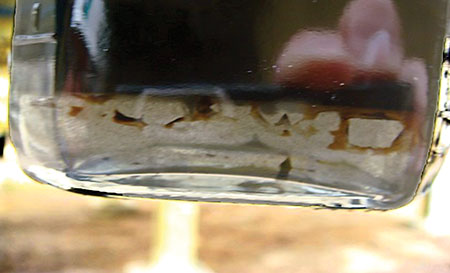
Fig. 11. Lube oil and water separated downstream of a compressor.
|
 |
|
Fig. 12. Iron sulfides plugging an inlet separator. |
Takeaway
To properly condition gas for further processing, it is critical to understand the contamination profile in the gas stream. Not only current contamination, but also future contaminants, should be considered. One example is shale gas, as many plants prepare to incorporate this type of gas into their feedstock. This gas stream has a number of different and specific contaminants, and proper design for their separation and removal must be evaluated prior to processing. The exercise of perfectly understanding the contamination profile will determine what separation system to use. Depending on the nature of the contaminant (liquid phase, solid phase or gas phase), the proper strategy can be used, as previously outlined.
It is also important to have proper vessel designs and coalescing elements, as these are the heart of the system. Also, it is often a serious mistake to design undersized vessels or vessels with deficient internal gas flow geometries. These will invariably cause contamination penetration and will ensure upsets in almost all downstream processing units.
Finally, it is important to stress that all separation systems must be closely monitored for online performance by measuring the contamination ingress and egress. This monitoring is necessary for modifying and optimizing the inlet separation system and, sometimes, for adjustments in feed conditions. This is the only way to ensure that contaminants are not penetrating separation devices and that each device offers the best protection for its individual design purpose. GP
 |
DAVID ENGEL has more than 20 years of industrial experience in a variety of areas, such as chemical synthesis, corrosion-resistant materials, sensors, light-to-energy conversion, membranes, nanotechnology, separation technologies, analytical methods and chemical additives. Dr. Engel is the inventor in 16 US patents and the author of a number of technical and scientific papers. He has developed business and technology for Eastman Kodak, Eli Lilly, Pentair, General Electric and Sulphur Experts globally. He has also presented seminars and technical courses on a variety of subjects. Dr. Engel has worked in a number of onsite field jobs and projects at many worldwide locations. Recently, he has specialized in advanced process systems and multicomponent separation methods, process efficiency and reliability, and plant throughput increases with minimal use of natural resources. Dr. Engel is the lead consultant and cofounder of Filtration Experts (Sulphur Experts Division) and the managing director of NexoSolutions. He holds a BS degree in industrial chemistry, a PhD in organic chemistry, and is Six Sigma certified. He is a member of the American Chemical Society and the Gas Processors Association, and is the president of the American Filtration and Separation Society, Southwest Region.
 |
MIKE SHEILAN is a chemical engineer with 30 years of varied industry experience. He has been involved in all aspects of the natural gas processing industry, primarily in relation to the chemicals used to treat gas and the processes that use these chemicals. He has provided expert advice and consulting services in the areas of hydrate control, gas dehydration, gas and liquid sweetening, hydrocarbon recovery and sulfur plant operations. Recently, he has focused on amine plant troubleshooting and plant optimization for the sour gas and oil refining industries. This includes working on plant startup and optimization projects for more than 100 facilities around the world. Mr. Sheilan is a well-recognized authority on gas processing and has published numerous papers on the subject, in addition to presenting papers at various conferences. He is a regular speaker at the internationally-recognized Sulphur Experts seminars, leading the amine sessions. In addition, Mr. Sheilan provides expert advice to clients and has performed onsite assessment and training for most of the major producers in the industry.


Comments