
Use integrally geared compressors for small-scale LNG
D. GRABAU, Cameron Process and Compression Systems, Buffalo, New York
In 2012, industry projections called for liquefied natural gas (LNG) supplies to grow 4.5%/year (yr) to 2030. This forecast rate of growth is over twice the rate of gas production (2.1%/yr) and faster than inter-regional pipeline trade (3%/yr).1
Since 2000, challenges in LNG terminal construction have driven machine manufacturers to design larger LNG trains, many of which have utilized gas turbines. Plant capacities in the past decade have expanded from 3.5 million tons per year (MMtpy) to 5.5 MMtpy, primarily due to the availability of large gas fields. Today, smaller, more remote gas fields have combined with several market drivers (e.g., limited pipeline availability, dropping spot prices, increased reserves and reduced capital budgets) to force end users to rethink design.
Although higher train capacities drive economies of scale, the challenge arises in building smaller plants and lowering costs. Stranded natural gas reserves, such as US and Chinese shale gas, make LNG the most feasible means of transporting and delivering energy to market. Through plant design standardization and increased equipment efficiencies, producers can achieve the best balance of economics, time-to-market and process flexibility. Recent projects have shown integrally geared compressors (IGCs) to be advantageous for small-scale liquefaction. Design considerations, such as zero refrigerant loss, high plant operational efficiency, use of electric drivers and appropriate specifications, are addressed here.
Also examined are the growing market demand for small-scale LNG plants, the requirements of mixed-refrigerant (MR) compressors, and the market sectors and key driving factors for LNG operations. Additionally, important features and evaluation factors for the main piece of rotating equipment in the liquefaction system, the MR compressor, are reviewed.
LNG market drivers. Historically, LNG industry leaders have been driving economies of scale through increased plant sizes. Since the 1970s, LNG train sizes have expanded from approximately 1 MMtpy to 7.5 MMtpy. The compressor drivers have also evolved from steam turbines to more economical, large-frame gas turbines and electric motors. This progression has proven valuable, but large gas fields are needed to feed these world-scale plants.
In its review of the global gas field outlook, BP forecasts that shale gas and coalbed methane (CBM) will account for 63% of North American gas production by 2030. The company also projects that 46% of China’s gas production growth will come from CBM and shale gas.1 Many of these fields are remote onshore (“stranded”) applications with no infrastructure to monetize the product.
Moreover, reduced natural gas spot prices and condensed capital budgets have led more companies to pursue small-scale LNG. While large-scale projects can take years to design, permit, construct and commission, small-scale LNG plants can deliver speed (i.e., time to market) and significantly reduce capital expenditures.
Aside from gas supply and spot pricing, other factors determining optimal plant size include market demand, operational flexibility, and optimization of storage and delivery methodology. Operational flexibility can be achieved through multiple small trains while retaining high levels of efficiency. Delivery methods can range from tractor-trailers to railcars, and normalized loading frequency can eliminate the need for large storage tanks. LNG is filling the gap in many markets, including remote gas delivery networks, peakshaving applications and transportation fuel markets.
LNG in the transportation sector. In the transportation market, there is an ever-present demand for clean, abundant energy sources. With the recent surge in natural gas supply in North America, LNG fuel can be approximately $1 cheaper per diesel-gallon equivalent. The cost to convert a commercial long-haul truck is less than $100,000, before tax incentives. At recent gas prices, owners can expect payback in less than five years.2
Beyond trucking, marine environmental regulations may indirectly promote the use of LNG as an alternative propulsion fuel. These regulations will limit harmful emissions such as sulfur oxides (SOx) and nitrogen oxides (NOx). Switching to LNG will greatly reduce these emissions while keeping gas a cost-competitive fuel.
Other benefits of LNG for transportation are storage capacity and range. LNG occupies 1/600 of the original volume of gas and can be stored at near-atmospheric pressure. When compared with compressed natural gas (CNG), an LNG tank of the same volume provides more than twice the overall range. The market drivers for natural gas supply and LNG demand indicate a generally positive outlook for the small-scale LNG industry.
A place for IGCs. A number of factors go into process technology and plant design selection; these include plant scale, energy cost, capital investment and operating plan. One commonly utilized design is single mixed-refrigerant (SMR). The SMR process offers high efficiency and requires fewer pieces of machinery than do other processes.
Once the optimal process technology is selected, front-end engineering design can begin for the main components, such as the cold box, coolers and MR compressor. The typical SMR process requires about 260 kilowatts (kW)–370 kW of energy per million cubic feet per day of LNG capacity. The exact value depends on the system design parameters, such as feed gas pressure, ambient conditions, and process specifications.3 The MR compressor is the main power consumer and is critical to plant operation.
The importance of MR compressors is known, but the drive arrangements for small-scale applications under consideration should be understood as well. World-scale LNG plants have seen a shift from steam turbine drivers to gas turbines for cost, equipment count and efficiency reasons. Electric motor drivers are becoming more prevalent at this large scale. An example is the Snøhvit LNG facility in Hammerfest, Norway, where compressors are driven by electric motors.4
Furthermore, gas turbine orders for mechanical drivers have continued to decline. A five-year trend shows a 46% drop in gas turbine orders from 2007–2011.5 Further studies have shown that electric motors can increase plant availability by 3%–4% over a gas turbine drive due to reduced maintenance and downtime requirements. When scaling down a large plant to 1/20 of its size—e.g., 6 MMtpy down to 0.3 MMtpy—the driver evaluation criteria remain the same, but the scales tip heavily in favor of electric motor drivers.
IGCs are well suited for electric motor drivers because there is no need for an external gearbox. The main motor speed is linked to the number of pole pairs and the frequency of the power net. Input speeds of 1,000 rotations per minute (rpm)–3,600 rpm
are increased by the large-diameter bull gear, which drives smaller-diameter pinions or rotors. These rotors surround the bull gear in an arrangement that allows for up to four pinions per gearbox. Each pinion has the capacity to drive two impellers mounted in an overhung configuration; this allows for eight stages of compression. Each pinion is optimally designed for a speed that matches the aerodynamic requirements.
 |
|
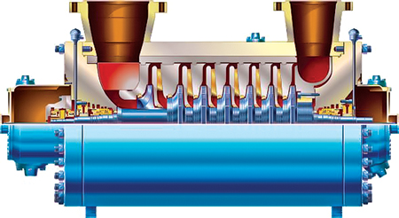
Fig. 1. An inline compressor. |
 |
|
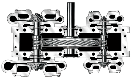
Fig. 2. An integrally geared compressor. |
When compared to inline compressors (Fig. 1), where all impellers are driven at the same speed, machine and stage efficiencies can be higher. Overall, the combination of electric driver and IGC (Fig. 2) offers a robust compressor solution for refrigerant services.
Most refrigeration systems rely on closed-loop circuits. For environmental and economic reasons, it is critical that no refrigerant is released to the atmosphere. One downside of IGCs, compared to inline compressors, is the need for additional sealing interfaces on the IGCs. This challenge is overcome by using dry face seal technology on all stages of compression.
For lower-pressure stages, tandem seals with intermediate labyrinths are employed. Tandem seals with carbon-ring separation seals are very effective for higher-pressure stages. Moreover, the secondary seals feature a recovery port that captures the majority of seal leakage ducted to the compressor inlet.
IGCs easily accommodate interstage cooling for even greater efficiency. Small-scale LNG plants tend to be air-cooled; seawater and closed-loop cooling systems are generally not available. Larger interstage pressure drops of 0.5 bar can be included in the design to accommodate the air coolers and associated piping runs. Moreover, when designing a refrigeration process, intermediate side streams can also be extracted or inserted, as each stage of compression is located in a separate casing.
IGCs also offer easier installation, a smaller footprint and faster commissioning than other compression technologies; this is attributed to several key design criteria. First, IGCs do not emit harsh vibrations or pulsations and, therefore, do not require special foundations. The civil engineering plan or foundation design only needs to support the static weight of the compressor package; this saves engineering costs and material.
Second, IGCs are designed to be packaged as a complete skid with minimal fieldwork. The package can incorporate the compressor, interstage piping, control valves, lubrication system, dry face seal support system and, in most cases, the main driver base plate. This comprehensive package minimizes customer connections and ensures quality control.
Additionally, the overall footprint can be reduced by 50% when compared to the external gearbox and driver arrangement for traditional inline compressors. Some small LNG plant concepts have been designed as a modular system and can be efficiently mobilized and erected for even greater speed-to-market than traditional layouts. Therefore, single-skid IGCs are effectively integrated into small-scale LNG plant designs (Fig. 3).
 |
|
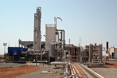
Fig. 3. An IGC installation at an LNG plant in Western Australia. |
IGCs are inherently oil-free, and several unique features ensure that no lubricant can enter the process gas stream. The main gearbox bearings utilize oil seals with grooved rings to eliminate oil migration along the pinion shaft to the process seals. Some manufacturers also include an atmospheric gap between the process seal and the oil seal to further separate the MR from contaminants.
Moreover, when compared to oil-flooded screw compressors, no separation equipment is required to remove the entrained lubricant from the gas stream. Separation equipment adds maintenance requirements and can also fail, sending oil containments into the MR loop. Centrifugal oil-free solutions are specified by many process licensors as the preferred compression solution. Table 1 compares reliability parameters for several different compressor types.6
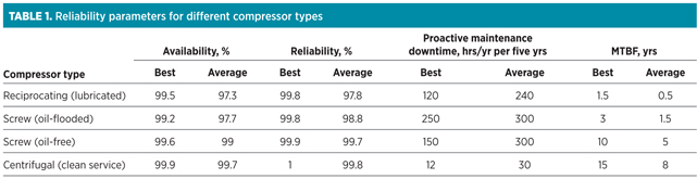 |
The reliability of the MR compressor is paramount to the successful operation of a liquefaction system. Centrifugal compressors are proven to have the longest mean time between failures (MTBF), and also show strong availability of 99.7%. This highly reliable solution is achieved with a five-year, continuous operation design philosophy, with several manufacturers reporting eight years of uninterrupted service.1 In contrast, screw and reciprocating solutions require far more maintenance, although they offer lower initial capital expenditures.
Takeaway. Small-scale LNG will play a predominant role in shaping the energy landscape of the future. With major players investing hundreds of millions of dollars in infrastructure and no sign of oil prices dropping dramatically, LNG is the economical, clean, portable energy of the future.
The sun is just beginning to rise on small-scale LNG. With the use of a standardized scope of supply, and process and compressor design integration, the future looks bright for IGC technology. GP
ACKNOWLEDGMENTS
The author thanks Cameron Compression Systems for its permission to present this article. The author also thanks Nauman Islam, Chuck Impastato and Trevor Grabau for their assistance with the content of this article, which is a revised version of a paper presented at LNG 17 in Houston, Texas on April 18, 2013.
LITERATURE CITED
1BP Energy Outlook to 2030, BP, January 2012.
2Van Loon, J. and E. Gismatullin, “Shale glut means $1-a-gallon savings at the pump,” Bloomberg, May 22, 2012.
3Price, B. and S. Hoffart, “Developing small-scale LNG plants,” Gas Today Australia, August 2010.
4Chellini, R., “GE Energy restructures, expands power conversion business,” CompressorTechTwo, June 2012.
5Haight, B., “Mechanical drive order survey,” CompressorTechTwo, June 2012.
6Bloch, H. P. and F. K. Geitner, “Use equipment failure statistics properly,” Hydrocarbon Processing, January 1999.
DAVID GRABAU is the product manager for process gas compressors at Cameron Process and Compression Systems. He has six years of experience in rotating equipment in the oil and gas industry, and has been involved in more than 50 projects for fuel gas boosting, refrigeration, gas processing and other initiatives. In his tenure, Mr. Grabau has helped develop new applications for integrally geared compressors in the oil and gas industry. He holds a BS degree in mechanical engineering and an MBA degree from the State University of New York at Buffalo.


Comments