
Nitrogen expansion cycle enhances flexibility of small-scale LNG
J. PAK, Cosmodyne LLC, Seal Beach, California
The abundance of natural gas from advancements in horizontal fracking technology applied to shale reservoirs has led to historically low natural gas prices in North America. In addition to being a domestic energy source that is environmentally friendlier than others (it emits up to 30% less greenhouse gas than gasoline or diesel), natural gas is now much cheaper than gasoline or diesel as an energy source. For these reasons, liquefied natural gas (LNG) is now a viable replacement for diesel in many high-horsepower industries such as drilling, mining and transportation, including marine and railroad.
This new paradigm has created excitement in the North American market, as well as around the world, for small-scale LNG plants where gas is liquefied and transported via truck to different demand sources, similar to the existing diesel market supply scheme. Typically, small-scale LNG plants are defined as plants with a total liquid production capacity of roughly 50,000 gallons per day (gpd) to 500,000 gpd [4 million standard cubic feet per day (MMscfd) to 42 MMscfd].
While mixed-refrigerant (MR) cycles dominate at world-class and medium-scale LNG plants, the reverse Brayton nitrogen (N2) cycle (or N2 expansion cycle) has enjoyed a resurgence at small-scale LNG plants. Here, the different liquefaction cycles available for small-scale LNG plants, and the specific factors that contribute to the N2 cycle becoming the cycle of choice, are examined. The unique factors discussed are the effects of recent advances in processes and equipment leading to improvements in efficiency, the use of pipeline gas as a feedgas source, capital vs. operational costs, and plant loading considerations.
Technology selection
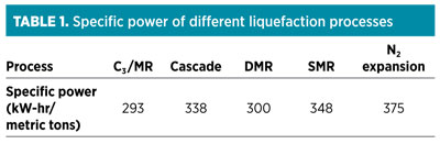
There are numerous processes available to liquefy natural gas. The MR and cascade cycles are the most efficient processes. Both types of hydrocarbon refrigeration processes allow for refrigeration loops to tightly match the cooling curve of a typical gas liquefaction, to achieve high refrigeration efficiency and reduce energy consumption (Table 1).1
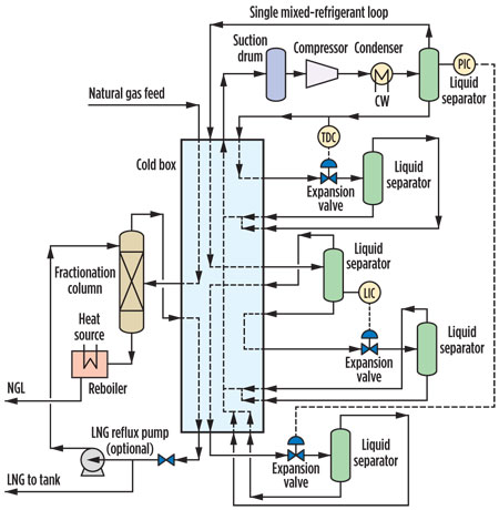
Most of the world's baseload LNG plants (i.e., plants producing more than 2.5 MMtpy) use an MR or a cascade cycle, which is a testament to the efficiency of these processes. The only practical natural gas liquefaction processes available for small-scale LNG plants are single-mixed-refrigerant (SMR) cycle (Fig. 1) and the N2 expansion cycle (Fig. 2). The processes used for world-class baseload plants do not transfer directly to small-scale LNG plants, as the complexity of the processes and equipment makes such cycles cost-prohibitive for small-scale LNG.
 |
|
Fig. 1. Flow scheme of a typical SMR process. |
 |
|
Fig. 2. Flow scheme of a typical N2 expansion process. |
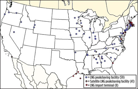
This preference for the SMR cycle over the N2 cycle, even for small-scale LNG plants, is clearly illustrated by peakshaving plants across the US. The majority of peakshaving plants (Fig. 3)2 in the US were built in the late 1960s and 1970s using the SMR process.3 At that time, most in the industry regarded the N2 expansion cycle as a well-established, robust and easy-to-operate technology, albeit one that was not competitive with the SMR cycle in efficiency. However, unique factors in today's LNG marketplace have made the N2 cycle a process of choice in many new, small-scale LNG markets in North America.
 |
|
Fig. 3. Locations of natural gas peakshaving plants in the US. |
Advancement of equipment efficiency
One of the factors in the resurgence of the N2 expansion cycle is the higher efficiencies achieved by both process design and rotating equipment. The nitrogen recycle compressor and the dual expander compressor package performance drive N2 expansion process efficiency. In recent years, the manufacturers of compressors and expanders have made significant strides in improving performance.
Manufacturers now utilize computer-aided engineering (CAE) tools such as computational fluid dynamics (CFD) and finite element (FE) software to optimize rotating equipment design. CFD and FE software programs have allowed manufacturers to bypass the traditional "trial-and-cut" approach, which requires extensive experimental tweaks. The computer-generated simulations, some of which are even in 3D, not only provide a more accurate and systematic approach to design, but they also give designers better understanding and insight on flow dynamics, pressure drops and stress loads. This allows the designers to optimize and develop more efficient scrolls, nozzles and impellers.
While these computer programs are tools and not the solution, they have allowed manufacturers to offer higher-efficiency rotating machines at lower costs. Most compressors and expanders now offer efficiencies that are much higher (sometimes greater than 10%) than units that were built in the 1960s and 1970s, during the installation of most peakshaving plants in the US.
In conjunction with CAE, computer-aided manufacturing (CAM) processes allow engineers to manufacture components designed with CAE. For example, most impellers are now milled from five-axis machines. This simple change in manufacturing has improved impeller efficiency by 2%–5% compared to old casting impellers.4 New computer-aided manufacturing processes using five-axis machines and computer numerical control (CNC) machine tools have allowed manufacturers to machine-sculpt diffusers and vanes for improved efficiency. Additionally, CAM permits much tighter tolerance for components, resulting in minimized losses (seal, leakage rates, etc.) and higher quality.
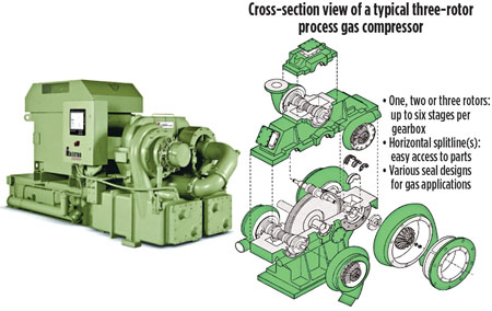
Furthermore, the range of integrally geared centrifugal compressors (Fig. 4) has steadily increased over the years. Larger integrally geared compressors have permitted the N2 cycle to be applied to larger-capacity LNG plants with competitive efficiencies. Integrally geared centrifugal compressors have higher efficiencies due to interstage cooling at each stage and the use of two or more pinion shafts for optimal impeller speeds. These compressors are also cheaper than API-type compressors. Due to their compact size, they require a smaller footprint for a simple and economical foundation.
 |
|
Fig. 4. Example of a typical integrally geared centrifugal compressor. Image courtesy of Cameron Process & Compression Systems. |
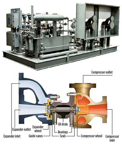
Since the integrally geared compressors and turboexpander units (Fig. 5) are used for N2 service, the manufacturer's standard rotating equipment can be used for the N2 cycle. This is not the case for some SMR plants where customized API rotating equipment is required. The manufacturer's standard equipment allows for readily available spare parts and support in addition to lower capital costs.
 |
|
Fig. 5. Example of a typical turboexpander used for small-scale LNG plants. Image courtesy of ACD. |
Integrally geared centrifugal compressors and expanders are now available for the full range of small-scale LNG plants. Improved rotating equipment efficiencies, reliability and costs from standard manufacturer designs have put the N2 cycle on par with the SMR process.
Pipeline gas as feedstock
The second dynamic contributing to the N2 expansion cycle's popularity is the source of feed gas for natural gas liquefaction plants. In North America, most small-scale LNG plants source their feedstock from gas pipeline networks and midstream gas processing plants.
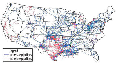
The US has an extensive natural gas pipeline network. With more than 210 gas pipeline systems and over 300,000 miles of pipeline, natural gas can be accessed at almost any location in the Lower 48 states (Fig. 6).5 This intricate gas pipeline network allows companies to strategically locate LNG plants to supply their demand sources. Fortunately, the pipeline gas is usually at high pressure and is lean, with few heavy hydrocarbons (C4+).
 |
|
Fig. 6. Diagram of the US natural gas pipeline network. |
In most cases, small-scale LNG plants need treat only the feed gas to remove carbon dioxide (CO2), water (H2O) and other impurities, and to liquefy the gas without removing heavy hydrocarbons. The combination of high inlet pressure and lean feedgas composition has allowed the N2 expansion cycle to achieve high efficiencies (specific power in terms of kW-hr/gal produced).
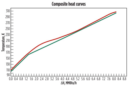
The cooling curve with feedgas pressure at 1,100 psig (Fig. 7) shows a flat natural gas heating curve that can be matched tightly to the N2 cooling curve for efficient heat transfer. The N2 cycle can achieve specific power values of 0.56 kW-hr/gal (350 kW-hr/metric ton) with high-pressure, lean feed gas.
 |
|
Fig. 7. Heating curve for feedgas inlet pressure. |
Moreover, pipeline feedgas composition frequently varies. This feedgas variation can impact the overall performance of the liquefaction plant. For the SMR cycle, the selection of specially mixed, multi-component hydrocarbon refrigerant must be adjusted to match the feedgas variation to maintain high refrigeration efficiency. If the refrigerant combination is not adjusted, then the SMR cycle's advantage over the N2 cycle may vanish.
The N2 cycle, on the other hand, is significantly more flexible than the SMR cycle in minimizing overall effects on efficiency and performance for ranges of ambient/cooling water temperatures and natural gas feed compositions. The N2 cycle uses nitrogen gas as the refrigerant; therefore, no adjustments are required for changing feedgas composition.
This process eliminates the need for a subsystem for the storing and mixing of several hydrocarbons to produce a multi-component refrigerant. Furthermore, combined variability of the recycle compressor and the two turboexpanders allows for more flexibility to minimize the effect on the overall liquefaction performance, with varying feedgas composition.
Plant loading considerations
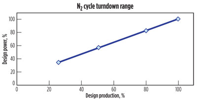
In the North American LNG market, plant operational flexibility is a key requisite in plant design. The turndown capability of the N2 expansion process meets this requirement easily. The use of LNG as replacement fuel for diesel in high-horsepower industries will take some time. Therefore, for some early-to-market developers, LNG demand during the early years of the plant life may fluctuate substantially, with a considerable ramp-up period, until full production capacity can be sold. The N2 cycle alleviates this problem by offering a wide turndown range with proportional power savings. Fig. 8 shows the typical turndown range of the N2 expansion cycle.
 |
|
Fig. 8. Typical N2 expansion cycle turndown (production vs. power). |
 |
|
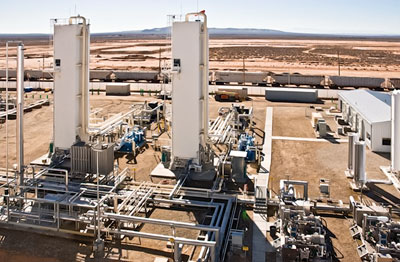
Fig. 9. An LNG plant with multiple trains. Photo courtesy of Clean Energy Fuels. |
The wide turndown range is especially beneficial when compared to plants that operate in "campaign mode," where the plant runs at full capacity until the storage tank is filled to a set level and then shuts down. The plant is restarted when the storage tank runs down to a low level setpoint. In campaign mode, the plant power rate is based on peak power draw, and the feed-gas supply agreement may have a mandatory minimum offtake.
Depending on the power utility and tariff schedule, there are rate adjustments or fees based on the maximum power draw used during a billing cycle. These costs can be lowered by operating the plant in turndown mode instead of in campaign mode (where the plant’s full power will be reached). Similarly, uncertain demand for LNG can make scheduling pipeline draws difficult, and it can result in unnecessary penalties for underestimating or overestimating the amount of pipeline draw. Therefore, operating the plant at a lower capacity can make scheduling more predictable.
Moreover, LNG plants under gas supply contracts that require minimum feedgas offtake will be penalized for operating in campaign mode because the LNG plant owner must pay minimum gas costs even when the plant is not in operation. The operating flexibility from the N2 cycle's turndown range allows an LNG plant operator to minimize operating costs, even during the early years of an LNG plant's life when market demand is lower than the full plant capacity.
Another key consideration in plant design is scalability to grow with market demand. Even though having a large, single train is more economical than multiple-train design, some LNG plant owners choose to go with the multiple-train option. The smaller multiple-train option allows for a highly modularized skid-mounted design for easier and cheaper installation. It even allows the plant to be relocated, since most of the components are skid-mounted. Additionally, the multiple-train design allows for a simpler and economical way to increase plant capacity by adding identical trains with market growth.
As a side benefit, multiple-train design also provides some redundancy; even with one train down, the plant will still be able to produce some LNG. More importantly, multiple-train design permits a company to make a smaller initial capital investment and retain the option to invest in increments as demand increases, reducing some of the risk for early market pioneers. This scalability of smaller trains, in lieu of a larger train, keeps the LNG plant capacity within the range where the N2 expansion cycle is competitive.
Capital vs. operational cost
In selecting an appropriate process cycle for a small LNG plant, it is important to understand the struggle between initial capital expenses (CAPEX) and operating expenses (OPEX).
Each situation has individual parameters that shape the struggle—i.e., internal rates of return (IRRs), with project life and power cost being the main factors. To understand the issues influencing the economic plan, it is standard to determine the lifecycle cost of the plant over the project life. In its simplest form, this is the sum of CAPEX and the present value of future OPEX.
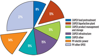
As an example, consider the data displayed in Figs. 10–12, which depict the segregation of various elements of lifecycle costs for a typical 100,000-gpd plant under project life assumptions of 10, 15 and 20 years. The model assumes a $310/gpd nameplate capacity starting at 50% loaded and increasing by 10%/yr until fully loaded, an IRR of 12%/yr, and a power cost of $60/Mwh. The liquefaction cost represents a low percentage of total lifetime cost.
 |
|
Fig. 10. Total lifecycle cost for a 10-year project life. |
 |
|
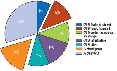
Fig. 11. Total lifecycle cost for a 15-year project life. |
 |
|
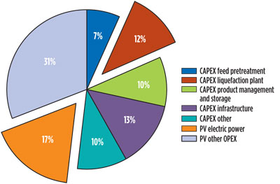
Fig. 12. Total lifecycle cost for a 20-year project life. |
As expected, the longer the project life, the more influential is the power cost. The lifecycle cost increases from $522/nameplate gpd at a 10-year project life to $598 at a 20-year project life. More importantly, the ratio of electric power to liquefaction CAPEX (the main power consumer) increases from 104% to 147%. Viewed another way, at a 20-year project life, an operator can afford to spend an additional 1.5% on equipment to save 1% on power, while, at a 10-year project life, an operator can spend 1% to achieve the same savings.
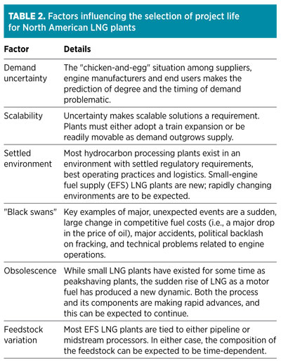
Short project lives are commonplace for a number of reasons (Table 2), and this has been favorable to the adoption of modern N2 cycle plants. These plants are traditionally lower in initial cost, are simpler to install, are easier to operate, have excellent turndown characteristics, are easily relocated and are feedstock-flexible.
In addition to the CAPEX and OPEX analyses, the ease of operation of the N2 cycle is an important factor because availability of qualified personnel with LNG experience is, and will be, limited as the LNG market grows. It is well established that N2 cycle plants are easy to operate. The N2 expander cycle is by far the most straightforward for operating staff to understand, operate and troubleshoot, because the process requires less monitoring and control points as well as minimal operator intervention compared to SMR plants.6
Additionally, inert, safe refrigerant eliminates the need for purging in and out for maintenance on the refrigeration side, making maintenance easier. Simple operation and minimal training for personnel have made the N2 cycle an attractive alternative choice in small-scale LNG plants.
Takeaway
There is no "one-size-fits-all" solution when examining the different processes for a small-scale LNG plant. Each process has advantages and disadvantages. Only an extensive comparison with definitive data and analysis can show which process is the right fit.
The N2 cycle is now the preferred process, even at capacities beyond the traditional limits, and it is enjoying a renaissance in the small-scale LNG market. The N2 expansion cycle, once viewed as a simple, easy-to-use process with low efficiencies, is now enjoying wider acceptance because of unique factors in today's LNG market. GP
LITERATURE CITED
112th International Conference and Exhibition on Liquefied Natural Gas, Perth, Australia, May 4–7, 1998.
2US Environmental Information Administration, “US LNG Peakingshaving and Import Facilities, 2008,” December 2008.
3Zeus Intelligence, Peakshaving Project Database, http://www.zeusintel.com.
4Cameron, “Centrifugal compressor performance upgrades,” 2010.
5US Environmental Information Administration, "US Natural Gas Pipeline Network, 2009," 2009.
6Pak, J. and K. Knight, “Keep on Trucking,” LNG Industry, Autumn 2012.
JOSEPH PAK is the director of sales and marketing for Cosmodyne LLC, a member of the Cryogenic Industries family of companies, in Seal Beach, California. He joined the company in 2007 and has since been responsible for the sales and marketing of air separation plants and small-scale LNG plants around the world. Mr. Pak has over 24 years of experience working for equipment manufacturers in various positions including engineering, sales and legal. He has an MS degree in mechanical engineering from the University of Southern California and a JD from the University of Connecticut School of Law. He is a registered professional engineer in California and is admitted to the California Bar.


Comments