
Digital Exclusive: Evolving pressure relief valve designs protect LNG facilities
C. CARROLL and R. GARCIA, Emerson, Houston, Texas (U.S.)
Liquefied natural gas (LNG) processing, storage, and transport has become a burgeoning industry, with numerous facilities under construction across the globe. Since LNG is a dense liquid, it enables the economic movement of large quantities of low carbon energy from producers to consumers. However, LNG must be kept quite cold, typically below -260 degrees F (-160 degrees C), so it poses numerous challenges for the equipment and instrumentation required to operate these facilities.
This article focuses on the pressure relief valves (PRV) that protect LNG storage tanks. This difficult yet critical application protects massive LNG tanks from overpressure and vacuum conditions that can quickly develop during operation. New designs are now available that can dramatically reduce fugitive emissions and save significant capital expense due to their extremely high capacities. These designs also incorporate instrumentation to monitor tank conditions, and to document release events should they occur.
LNG storage applications. Natural gas is widely recognized as an immediately available, lower-carbon energy source compared to coal or oil, but gas production can be located far from consumers. Pressurized gas can be efficiently moved in pipelines when that media is available, but transport between continents will usually require some form of ship transport. To improve the economics and take full advantage of the relatively limited capacity of cargo ships, natural gas is cooled and liquified to increase its density. The resulting LNG product is then stored at ship terminals, transloaded to large LNG tankers, and moved around the world (FIG. 1). The ships are offloaded into storage tanks at the port of entry, then the gas is ultimately transported via truck or pipeline to the ultimate consumer.

FIG. 1. LNG port terminals transfer product between ocean going ships and onshore distribution. Most LNG storage tanks are massive in size and are located onshore and on ships.
Storage of LNG at the ports as well as on ships is a challenging application. The LNG tanks are typically massive and incapable of handling significant overpressure or under pressure without catastrophic damage. The cryogenic liquid itself must be carefully insulated from ambient heat because heat transfer can vaporize the liquid, resulting in product loss, or requiring more energy to capture and re-liquify the gas. The very low operating temperatures are difficult for materials of construction selection, and the equipment is prone to icing.
Relief valves for LNG storage tanks face a number of particularly difficult requirements, and the first is sizing. Changes in atmospheric conditions, high pumping rates, and ambient heat transfer can create a need for near instantaneous pressure venting or vacuum relief. Most vents must also be sized for fire exposure, creating a massive pressure venting scenario that may require several PRVs.
The PRVs must also maintain tank pressure within a very tight band of pressure and vacuum since the tanks are only capable of handling very limited excursions of these parameters. Due to the low pressures involved and the small difference between normal operating pressure and pressure setpoint, many PRVs tend to leak, resulting in lost product and fugitive emissions. Ice formation can also be a problem because this may impede the vent from opening when required.
LNG storage tank PRV design. A standard weight loaded, low pressure relief vent is typically a poor choice for LNG storage tank service. This type of vent uses the weight of the disc, and/or additional weights, to offset the tank pressure. When the pressure reaches setpoint it overcomes the weight and pushes the vent open. As pressure increases, the vent opens more, until it is fully open and operating at full capacity. Such a design tends to have limited capacity and leaks badly as tank pressure approaches setpoint since the force on the seat is approaching zero (FIG. 2). It also requires the PRV setpoint to be set at a relatively low level to allow enough accumulation, typically 100% overpressure, for the device to reach full capacity at design pressure. This results in increased fugitive emissions when the vent is operating near setpoint, and it increases LNG product releases since the vent opens earlier.

FIG. 2. A low-pressure pilot (LPP) valve can be set just below design pressure, maintaining a tight seal up to setpoint.
In contrast, a low-pressure pilot relief (LPP) valve utilizes a very different means of controlling the PRV opening. As shown in FIG. 3, the pilot valve diverts system pressure to the dome when system pressure is below setpoint. Since the main valve diaphragm is larger than the main valve seat, downward sealing force is high and increases as the valve nears setpoint. This keeps leakage to a minimum.

FIG. 3. An LPP valve uses system pressure to keep it seated. Since the main valve dome area is larger than the main valve seat, sealing improves as pressure rises. The pilot valve exhausts the dome pressure at setpoint, allowing the valve to open.
When the tank pressure increases and reaches setpoint, the pilot valve opens to release dome pressure, thus opening the valve.
The performance difference of an LPP valve is shown in FIG. 2. The PRV can be set just below design pressure, while still providing the required capacity at full lift. This allows the PRV set pressure to be raised to within 90% of design, minimizing valve release events. The LPP valve also seats much better when operating near setpoint, so fugitive emissions and product loss are dramatically decreased. Finally, the design allows pilot adjustment to be set to either snap or modulating action to suit the application. A snap-acting PRV immediately opens to full lift at setpoint and closes as pressure falls below setpoint. A pilot set to modulating action, however, will only open the valve in proportion to the rise in tank pressure, so lift is dependent on the magnitude of the relief event. This in turn minimizes the amount of product being released rather than with a full-open relief event, as with snap-action.
Recent upgrades to LPP valve designs incorporate double seats to reduce leaks and avoid ice formation, and a new body design can achieve extremely high flow capacities. Very large LNG storage tanks require enormous safety venting capacities which are usually achieved using multiple PRVs per tank. Each PRV requires tank connections, structural support, and vent piping so if a PRV system needs higher capacity, significant capital savings can be achieved by reducing the number of valves, often to just one.

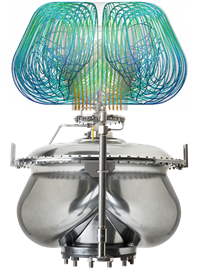
FIG. 4. Extremely high-capacity low pressure pilot relief valves can meet LNG storage tank relief requirements with fewer valves, sometimes just one, and reduced installation costs.
Advanced LPP valve features. While very high capacities, significantly low leakage rates, and repeatable performance in a very tight deadband are extremely advantageous in an LNG storage application, there are additional benefits to using an LPP valve.
One common application for LNG storage service is a pressure relief/vacuum relief combination. Tank pressure can fall quickly when product is removed from the tank, potentially creating a vacuum, which most storage tanks cannot withstand at any but very minimal amounts. Rather than install separate pressure and vacuum relief devices, a single PRV can provide both overpressure and under pressure protection (FIG. 5), with a pilot-operated pressure setting and a weight-loaded or pilot-operated vacuum setting. This design saves on installation costs, and it has the same very high-capacity capability when operating in pressure or vacuum modes.

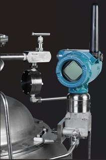
FIG. 5. Some pilot-operated PRVs offer a dual pilot arrangement, allowing a single high capacity PRV to provide both pressure and vacuum protection. A multivariable transmitter can be added to monitor tank pressure and quantify relief events.
A multivariable pressure transmitter can be added to monitor both the tank pressure and the differential pressure between the tank and the valve dome. The tank pressure reading provides a continuous indication of tank pressure and vacuum. The differential pressure measurement between the tank and the dome provides a means to track and quantify flows during valve relief events.
CASE HISTORY
One LNG storage tank user was encountering continuous problems with their existing PRVs. The valves leaked product in normal operation, and a lack of visibility of tank vacuum led to frequent vacuum relief events, creating product quality issues. Moss storage tanks were used, which utilize a double-wall tank with a void space to insulate the LNG. The void space pressure was variable, so the vacuum relief setpoint needed to reference the differential between the tank pressure and the void space to work properly.
The solution was a dual pilot valve with a multivariable pressure transmitter (Figure 6). This design provided both pressure and vacuum protection in a single device, and the LPP provided much tighter pressure relief response as it could be set just below the design pressure to minimize PRV events. The result was dramatically reduced leakage and product loss since the seat is now subjected to high differential sealing pressure, even as the PRV approaches setpoint. The vacuum relief pilot references the tank void space pressure, providing consistent and reliable vacuum relief protection, despite variable void space pressure.

FIG. 6. This dual pilot PRV design allows a single PRV to provide pressure and vacuum relief, with the vacuum referenced to the Moss tank void space. A multivariable DP pressure transmitter (shown in blue) monitors tank pressure, along with PRV event duration and quantity.
While the PRV performance was dramatically improved, the data provided by the pressure transmitter proved to be invaluable to the operating staff. Continuous visibility of the tank pressure and/or vacuum were extremely helpful during loading/unloading operations. If the PRV did lift, the production staff immediately knew the time and duration of the event, as well as the amount of product that was vented.
In this and other applications, PRV monitoring data provides critical information for root cause failure analysis after a pressure or vacuum relief event. This data can also be used to drive optimization of maintenance schedules to minimize downtime.
Consider the options. When facing a need to install new or replace existing PRVs on an LNG storage tank, users should investigate the latest technologies for this service. Larger, high capacity PRVs can significantly reduce installation and capital cost since a single device can provide both pressure and vacuum protection. Moreover, the LPP design with its dual seats provides reliable and very low leakage performance, while operating within 90% of set pressure.
Another benefit is the addition of a single transmitter to provide both tank pressure/vacuum and PRV event data. Tank pressure/vacuum data can be very helpful to production staff to keep the tank operating pressures within specifications. Should a pressure or relief event occur, the transmitter provides a clear indication of when the event started and stopped, and how much flow passed through the PRV while it was open.
ABOUT THE AUTHORS
Caitlin Carroll is a Global Product Marketing Manager for Emerson, specializing in pressure relief valves. She has been with Emerson for seven years, where her career has focused on value growth, especially within the LNG market. Caitlin earned a BS degree in mechanical engineering from Texas A&M University.
Ricardo Garcia is a Product Marketing Director for Emerson, specializing in pressure relief valves and digital transformation. He has 14 years of experience in the process industries, and his expertise includes advanced pressure relief valve monitoring technologies and their applications across LNG, chemical and other critical process environments. Garcia focuses on helping facilities improve reliability, safety, and performance through data-driven insights and modern digital solutions. He earned a BS degree in industrial technology management from Missouri State University. 
Related News
Related News

- Mitsubishi Heavy Industries Compressor acquires Swiss rotating equipment maintenance company AST Turbo AG
- RWE strengthens partnerships with ADNOC and Masdar to enhance energy security in Germany and Europe
- Qatar’s Ras Laffan LNG hub hit by missile attack, ‘extensive damage’ reported
- Cook Inlet LNG advances FSRU project in Alaska (U.S.)
- The Mugardos Energy Terminal is now ready to supply bioLNG to ships and tankers

Comments