
Mitigate fouling in process units via advanced analysis
Fouling, or the undesired accumulation of solid material on a surface, is an increasingly prevalent and challenging problem in processing plants across many industries. As plants move to reduce costs, contaminated feedstocks and ineffective process protection lead to higher fouling rates and associated problems. The costs associated with fouling problems have been estimated at more than $4.37 B/yr in the U.S. alone in 2019.
Filter plugging and reduced lifetime, reduced heat transfer in heat exchangers, column packing obstruction, and reduced throughput are a few of the harmful effects caused by fouling, in addition to under deposit corrosion. Plants must maintain low costs and high throughput to achieve profitability; therefore, the need for root-cause analysis and cost-effective fouling solutions is critical. Several different techniques, including advanced analytics and expert troubleshooting, can be utilized to mitigate fouling, depending on the nature of the situation.
Proactive solutions. The tendency of a fluid to foul process equipment is related to many factors. This is generally caused by suspended solids, dissolved components or separate liquid phases such as emulsions (and the potential combinations thereof). Predicting fouling tendency based on process conditions and stream quality alone is often speculative and inaccurate. A good method for determining fouling tendencies is a validated laboratory simulation of the process and its conditions.
Hot liquid process simulator. One of the best laboratory tests used to simulate process conditions to determine fouling tendencies of a process fluid is the hot liquid process simulator (HLPS). The HLPS is a dynamic laboratory bench apparatus used to simulate fouling in a scaled-down and accelerated way (FIG. 1). By using actual process fluids in the test, the HLPS produces essential information related to process fouling and keeps plants a step ahead of fouling events. This article describes how the HLPS was used to identify the root source of fouling in an aqueous stream, and enabled the facility to devise a more informed and effective mitigation strategy.
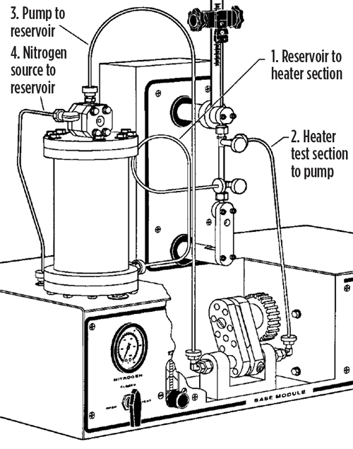 |
| FIG. 1. The hot liquid process simulator (HLPS). |
The HLPS consists of a reservoir charged with the sample fluid that is pumped through a test section. Electrically heated metal elements or rods (FIG. 2) positioned vertically in the test section form an annulus through which the fluid flows, and the temperature of the element is controlled by a thermocouple located in the interior. Process conditions are simulated by adjusting the flowrate of the fluid and the temperature of the elements or rods. The temperature can be adjusted up to 650°C, and the system is typically pressurized to 600 psi with nitrogen to prevent vaporization of volatile components in the process fluid.
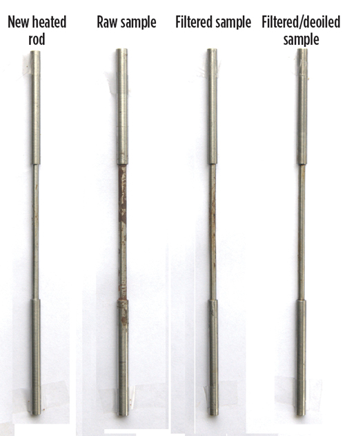 |
| FIG. 2. Heated metal rods used in HLPS testing of treated and untreated aqueous samples. Hydrocarbon deposits and increased total deposition were observed on rods used in the testing of non-extracted samples. |
The HLPS measures the degree of fouling by differential temperature (∆T) or differential pressure (∆P), depending on the nature of the process fluid. In ∆T mode, the temperature of the fluid at the inlet of the annulus is compared with the outlet temperature. As foulant material deposits on the heated element, heat transfer from the element to the fluid deteriorates, and a subsequent decrease in the outlet temperature is recorded (FIG. 3). In ∆P mode, the fluid is pumped through the annulus into a small, 1.7-micron filter. Any foulant material in the fluid, generated by exposure to the heated element in the annulus, will accumulate in the filter and cause the differential pressure to increase as a function of time.
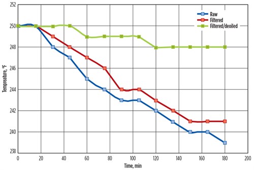 |
| FIG. 3. Outlet temperature data produced from HLPS testing of treated and untreated aqueous samples (inlet temperature maintained at 250°F). |
Fouling tendency analysis can be used to predict fouling in many liquid streams, both aqueous and hydrocarbon, and the produced foulant material can be subjected to further analysis to proactively determine the best feed contaminant removal method for the process. Determination of fouling tendency using the HLPS is a powerful tool that can help assess the impact of processing feedstocks and intermediates (aqueous or hydrocarbon-based). In relation to filtration and other separation processes, fouling tendency analysis is useful for determining the optimal treatment method to address fouling issues. This has a fundamental impact in determining whether filtration is the most effective mitigation strategy for a given process fouling event. It also can be used to investigate other alternatives, such as liquid contaminant or emulsion removal (often via coalescence) or chemical additive treatments. As such, the HLPS test is an invaluable test for fouling root-cause determination, as well as mitigation strategy determination.
Case study. A natural gas processing plant in North America was experiencing severe problems with fouling at its methanol recovery unit distillation column and prefilters. The feedwater contained between 50 ppm and 70 ppm of suspended solids and approximately 1% of hydrocarbons. Fouling of the tower packing and filter plugging caused excessive maintenance, reduced throughput and decreased efficiency, and impacted the efficiency of other units downstream. The methanol recovery unit was evaluated, including a comprehensive analysis of the feed components and the process, to find the best solution for fouling reduction.
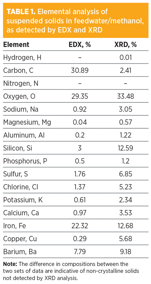
The feed composition was first analyzed to understand the nature of the contaminants and the feed itself. Visual observation of feed samples revealed high free hydrocarbon contamination (1%) and high suspended and settled solids. X-ray diffraction (XRD) and energy-dispersive X-ray spectroscopy (EDS) analyses were performed on suspended solids from the feed and showed a wide range of contaminants (TABLE 1). Large amounts of iron and carbon undetected by XRD analysis were present in the EDS results, indicating an amorphous deposit typical of asphaltene precipitation and hydrocarbon-coated solids. The HLPS test system was used to determine the fouling impact of these solids and hydrocarbon contaminants.
 |
Three samples were tested by HLPS: an unaltered sample, a filtered sample and a filtered sample with free hydrocarbon removed. The study conclusively showed that fouling of the test element was greatly reduced after hydrocarbon removal (FIG. 2). Deposition of foulant material on the test elements, as well as a marked decrease in differential temperature, was observed in those samples where hydrocarbon was not removed prior to HLPS testing (FIG. 3). With the results of this testing, plant engineers in the methanol recovery unit were able to proceed with a better understanding of fouling reduction by focusing on hydrocarbon removal in addition to solids filtration. However, it is important to stress that in this case, if filtration improvement alone had been recommended based on the high particulate matter, the overall impact on fouling would have been marginal. The key solution in this case was to remove suspended solids by adequate filtration in combination with hydrocarbon separation and recovery from the feed stream.
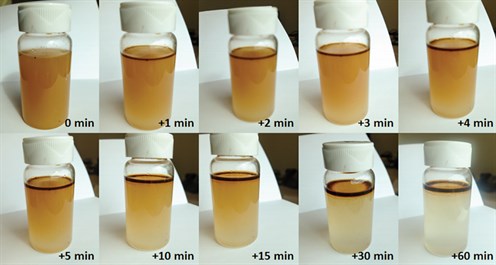
It was established that the source of hydrocarbon contamination in the feed arose from inefficiencies at several upstream three-phase separators. The installation of an oil-water separator at the methanol recovery unit feed inlet was recommended. To understand the separation rate of the hydrocarbon from the bulk feedwater, a time-lapse study was performed (FIG. 4). The feedwater sample was shaken to homogenize, and the phases were allowed to separate into organic and aqueous component phases over the course of 1 hr. Separation was complete in 30 min–45 min, indicating that a residence time API device for an oil/water separator would be an efficient system for hydrocarbon removal.
 |
|
FIG. 4. Time-lapse study of phase separation after homogenization of feed samples. After 30 min, the hydrocarbon and water in solution had almost completely divided into separate phases. After 1 hr, the aqueous phase is clear, indicating the absence of free or emulsified hydrocarbon. |
The filtration system in place for the feedwater consisted of two bag filters set in parallel and run in rotation. The filters (FIG. 5) were nominally rated for 10-micron (nominal 80%–85% efficiency) particle capture (no efficiency information was available) and were observed to have low efficiency in removing smaller particle sizes. Due to the particle distribution (FIG. 6) and hydrocarbon contamination, the filters were also plugging rapidly, causing reduced filter lifetimes and increased filter changeouts. An upgrade to the filtration system was recommended to improve solids retention, accommodate smaller particle sizes and hydrocarbon contaminants, and increase filter lifetimes. The recommended glass microfiber-based filter was pleated to increase the available surface area and to reduce pressure drop across the newly installed elements. The filter vessels in place were reconfigured to accommodate these cartridge-style elements and improve the solids removal efficiency in the feed stream, in addition to increasing filter online life.
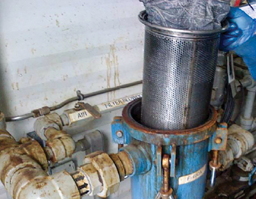 |
| FIG. 5. Bag filter and filter vessel in place at the feed to the methanol recovery tower. The 10-μm nominal rated filters were experiencing low solids removal efficiency, rapid plugging and short online life. |
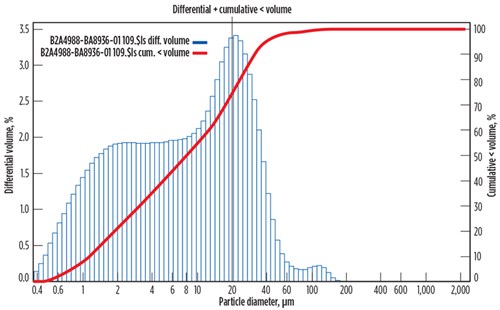 |
| FIG. 6. Particle size distribution of suspended solids in the feed to the methanol recovery tower. |
Root cause troubleshooting and analytics. A thorough and holistic understanding of process conditions and appropriate root cause analysis are key to resolving fouling and other issues. Specialized analytics and data interpretation are necessary for finding and resolving root cause problems that contribute to fouling episodes. Filtration systems can be analyzed for solids removal efficiency, often revealing the real solids removal efficiency and the impact on downstream fouling. Coalescing systems in both gas and liquid streams also can be effectively and quickly tested to provide valuable insight about actual separation performance and contaminant breakthrough.
Several resources and strategies can be used to determine the best path forward for fouling mitigation, and the best possible solutions can be identified using advanced analytics, expert troubleshooting and innovative, results-oriented solutions. The ability to identify sources and mechanisms of fouling is vital to plant operations, and every fouling issue should be approached differently and proactively, with proper analytical techniques. Only then can suitable separation technologies be conceived, designed and implemented effectively.
When dealing with fouling challenges in aqueous streams, such as the case described previously, it is important to look at the problem with an unbiased perspective and a holistic approach with due consideration to processes upstream. Produced and/or sour water streams vary dramatically in their sources, compositions and contamination profiles; therefore, their fouling tendencies and contamination separation strategies can also vary greatly.
FIG. 7 shows a series of photographs of several process sour waters and produced waters in plants around the world. Upon visual inspection, it can be immediately seen that the variability of these water streams is substantial. Hazy samples are consistent with micro-emulsified hydrocarbons and, in some cases, dispersed suspended solids. Samples with suspended solids presence indicate considerable upstream contamination or corrosion. With respect to separation alternatives, streams with both hydrocarbons and suspended solids pose the most complex scenarios for effective contamination removal. The interaction of both contaminants can, in many cases, generate gel-like materials that can film over filters and coalescers or any other surface. This will rapidly cause plugging, leading to an increase in differential pressure, thereby considerably shortening the working life of any separation system. Similarly, the modes by which fouling occurs in the different process streams vary based on the contaminants present, as well as the process conditions.
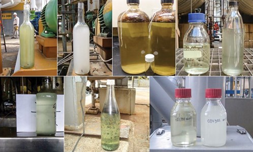 |
| FIG. 7. Photographs taken of sour and produced waters from several different processes. |
Several ways exist to deal with fouling in sour or produced process waters. Identifying fouling causes, possible mechanisms and tendencies is critical to eliminate or reduce process fouling. The presence of dissolved components, suspended solids, hydrocarbon or water phases and emulsions should be tested, analyzed and correlated with fouling when possible. These parameters must be carefully monitored to anticipate potential fouling events. Changes in fouling tendency with changes in process conditions (T, P, flowrate, etc.) should be carefully monitored. When fouling events take place, methods like the HLPS and other techniques can be used to understand potential fouling mechanisms. This will enable proper solutions or mitigations for fouling to be impemented. GP
 |
SCOTT WILLIAMS is a Process Engineer at Amine Optimization. He has industry experience in a number of projects in oil and gas, petrochemical, chemical and water treatment applications. As part of the Amine Optimization engineering group, Mr. Williams is responsible for technical design and solutions development in engineering and technology applications. He also provides support for analytical and specialized service projects. His recent work has been focused on amine unit contamination control, process stability and energy reduction. Mr. Williams holds a BS degree in chemical and biological engineering from the University of Colorado at Boulder.
 |
DAVID ENGEL has more than 25 yr of industrial experience in a variety of areas of chemical engineering, chemistry and material sciences. He is the inventor in 21 U.S. invention patents and the author of more than 90 technical and scientific papers. He has worked in several technical and business capacities for companies such as Eastman Kodak, Eli Lilly, General Electric and Sulphur Experts, among others. Dr. Engel specializes in chemical engineering, process chemistry, optimization and contaminant removal technologies, and new green technology development. He is the Managing Director of Nexo Solutions Companies and sits on the Board of Directors for Exion Systems and Paico Investments. Dr. Engel is also a Committee Member of the American Filtration Society, Southwest Region and a member of the Gas Processors Association Technical Section M, in addition to a member of the boards of directors at several companies. He holds
a BS degree in industrial chemistry, an MS degree in chemistry and a PhD in organic chemistry. He is also Six Sigma and Project Management certified.


Comments