
Innovations to reduce cost and schedule for small-scale LNG
A small-scale LNG (ssLNG) plant does not equate to small design challenges. On the contrary, a small LNG plant requires additional effort to minimize capital and operating costs in a wider and somewhat more unpredictable operating window. It is, therefore, critical to offer a design that is robust and flexible for all the expected operating cases, while at the same time avoiding unnecessary plant complexities.
Growth potential for ssLNG. In the coming decade, increased interest in LNG for transportation, peakshaving, power generation and marine fuel (bunkering in support of IMO regulations) is expected to significantly expand the need for ssLNG liquefaction plants. In this article, ssLNG refers to plants producing approximately 100 tpd–500 tpd of LNG. These plants are about 100 times smaller than baseload plants, so the economic, technical and project requirements are very different. This article provides insights into the key factors for an economic ssLNG facility. In particular, the ssLNG plants require new and innovative approaches to the technical, project execution and commercial challenges, compared to the traditional, large, baseload LNG facilities.
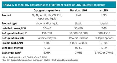
To develop the best ssLNG solutions, it is useful to start from a proven base. TABLE 1 compares some key characteristics of these technologies. As can be seen in TABLE 1, ssLNG has some common features with both cryogenic separations and baseload LNG. In technical and project scale, it is similar to cryogenic air separation units (ASUs); in product, it is similar to baseload LNG. Therefore, the best ssLNG projects will use the experiences and lessons from both sources.
 |
LNG process improvements. A key decision for ssLNG is the liquefaction process cycle. The two basic process types are boiling mixed refrigerant (MR) and gas expansion.1 In MR, the main refrigerant is typically a mixture of low-boiling hydrocarbons and N2, and the refrigeration comes from boiling this mixture. The heat transfer coefficients are very high, which allows efficient heat transfer equipment. MR has high efficiency because it can be designed to give the smallest temperature approaches within the liquefier.2 The MR supplies refrigerant by using the reverse Rankine cycle, which consists of four basic steps:
- Compress vapor MR
- Condense the MR
- Lower the pressure over a valve
- Evaporate the MR to supply refrigeration, and return to step 1.
Gas expansion uses an all-gas refrigerant, typically either CH4 or N2. Gas expansion processes tend to have simple operation since there is only one vapor phase. However, the vapor phase density is significantly lower than the other refrigerants, potentially requiring larger heat exchangers and piping in the refrigeration loop. Gas expansion processes have lower efficiency. The gas expansion supplies refrigeration through the reverse Brayton cycle:
- Compress vapor
- Cool vapor
- Expand vapor in a turboexpander, further reducing its temperature
- Warm the cold vapor to supply refrigeration and return to step 1.
To select the optimum process for ssLNG, it is useful to look at the history of ssLNG. The first peakshaving plants were built with MR processes; however, in the past 20 yr, virtually all ssLNG peakshavers in the U.S. have been gas expansion processes. The reasons include:
- Lower operating complexity
- Readily available equipment
- Greater ease of operation (including fast startup/shutdown)
- Lower cost of refrigerant, including both supply and storage
- If N2 is the refrigerant, it is non-flammable and can be vented with no environmental issues
- Improved machinery efficiency and reliability for turboexpanders.
These reasons generally overrule the gas expansion process having lower efficiency (i.e., higher OPEX). For plants where OPEX is more important (e.g., with high power costs), MR processes may be more economical.
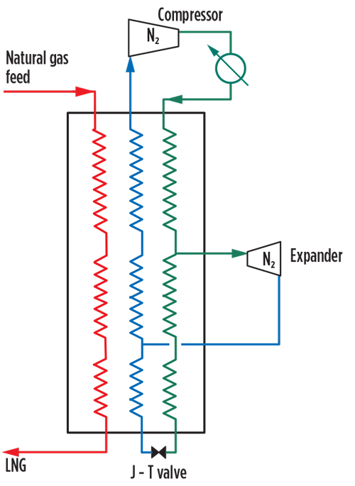
Nitrogen expansion process for ssLNG. The N2 expansion cycle is widely used in ssLNG facilities, as well as in some medium-scale facilities, because it reduces the flammable gas inventory, process/operating complexity and capital expense. The N2 expansion process uses nitrogen as the refrigerant, eliminating the need to source and store hydrocarbon refrigerants found in MR processes. N2 is readily available and can be vented without the need to flare.
Although the process has lower efficiency than MR processes, it does have lower capital investment. The process can be configured with one expander (FIG. 1). It can also be configured with two or three expanders, as well as one or two pressure levels, which can improve efficiency at the expense of higher capital and increasing operational complexity. The process can be designed with a refrigerant mixture of methane (feed gas) and N2 as a simple way to boost process efficiency. Note: Blending methane into the nitrogen refrigerant will require flaring if the refrigerant inventory must be reduced.
 |
|
FIG. 1. Single-expander nitrogen expansion process. |
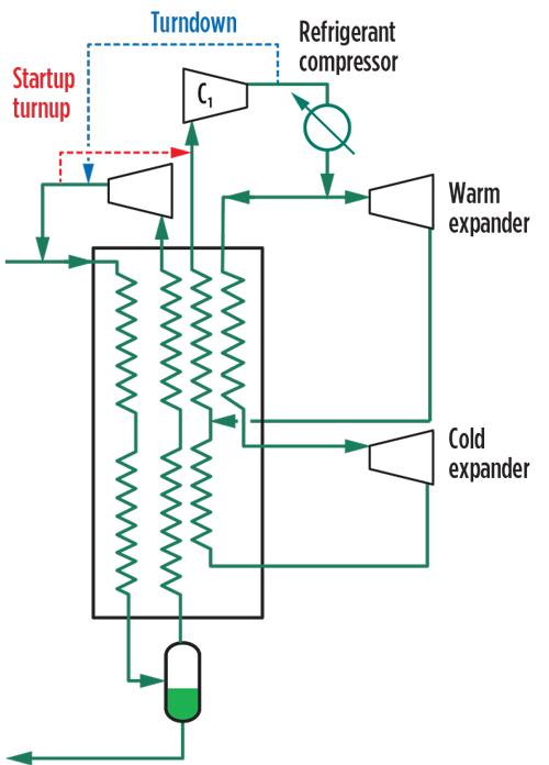
Methane expansion process for ssLNG. The proven methane expansion process uses feed gas as the refrigerant, thereby eliminating the need for external refrigerant components (e.g., N2 or C2+) and reducing the refrigerant import and storage costs. The efficiency of this process, using two expanders, is comparable to single mixed-refrigerant (SMR) processes. The methane expansion process can be configured to be either closed loop or open loop; FIG. 2 shows the closed-loop flowsheet.
 |
|
FIG. 2. Closed-loop methane expansion process. |
A unique feature of the closed-loop process is its ability to charge and recover refrigerant from the refrigeration loop, using the feed gas. During startup and production rampup, feed gas is sent to the suction of the refrigerant compressor, increasing the refrigerant circulation rate and, thereby, the production capacity. In the reverse, methane is sent from the refrigeration compressor discharge to the feed circuit during turndown or prior to liquefier shutdown, thereby recovering and converting the refrigerant molecules to LNG product. This feature greatly reduces the need to vent or flare the refrigerant molecules compared to other process cycles.
In the simplest open-loop configuration, the expander discharge can be sent to a low-pressure system, such as an LP pipeline. The open-loop configuration is particularly well suited when there are two pipelines of different pressures. This process can then convert natural gas to LNG by taking advantage of the pressure differential between the pipelines, eliminating the need for a compressor to supply power. Expanding a portion of the feed gas provides the necessary refrigeration to liquefy LNG. Alternatively, a portion of the expander flowrate can be compressed and recycled to the feed. This process has been used for peakshaving plants and considered for boil-off gas (BOG) reliquefication and for LNG production at natural gas letdown stations.
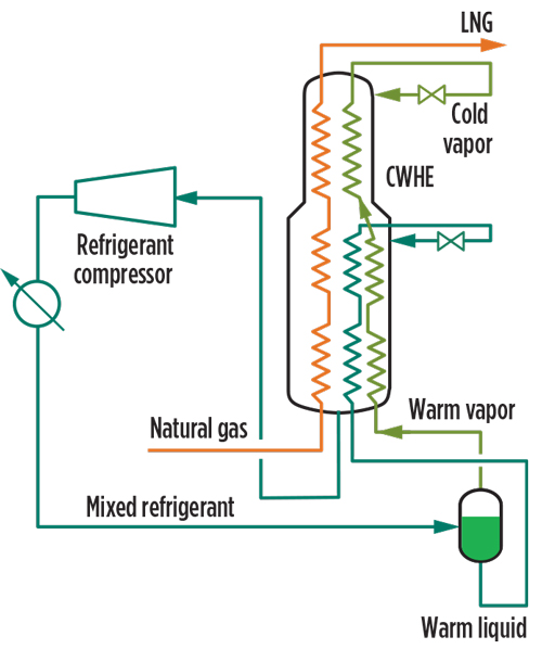
SMR process. When larger capacity (e.g., > 500 tpd) is required, an SMR process with the use of a CWHE can be considered. Liquefaction occurs in a CWHE because the CWHE provides large throughput in a small footprint. It also gives enhanced performance and reliability due to its robust mechanical and structural design.3 Warm streams flow up inside the spiral-wound process tubes, and the cold MR boils while flowing down through the shell side of the heat exchanger, offering excellent heat transfer performance and greater stable operation range. While the SMR process for most mid-scale applications uses a three-bundle CWHE, it can be configured to have two process bundles for ssLNG applications to balance good thermal efficiency with simpler design and less piping and equipment (FIG. 3).
 |
|
FIG. 3. Two-bundle SMR process. |
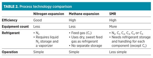
Technology selection is always the first step in developing technical solutions for an LNG project. The ultimate choice is dependent on many factors, and it is important to understand the critical success factors for the project. Each process technology described (FIGS. 1–3) has been used in ssLNG applications. TABLE 2 highlights some of the key considerations in selecting the process technology.
 |
Standardization and modularization. A key requirement of ssLNG is to have a short project schedule and to enable LNG production more quickly after the final investment decision (FID) is taken. Also, shorter schedules tend to reduce CAPEX, especially by reducing field construction time. It has been proven through vast experience that one method to reduce schedule is the use of standard components. Typically, this has not been done for the large baseload plants because there are only a few plants under construction at any one time, and each facility is unique. Also, because the production and plant scales are so large, small customization is economically justified.
It is common to consider standardized components to reduce schedule and costs. Whenever standard components are used, one of two things occurs:
- The component is overdesigned—i.e., it has more capacity and features than required for the specific need
- The customer requirements must be adjusted to stay within the limits of the component.
These inefficiencies and/or extra costs can be outweighed by reducing the design and procurement expense and time.
How are standard components integrated into ASUs? Portions of the ASU are predesigned, with equipment selected and vendors qualified. When a customer need arises, the components are configured and rated to meet the specific need. Site-specific conditions, such as feed gas composition and pressure, available cooling medium and ambient temperature ranges, must also be factored into the design to maximize the benefits of standardization. Once selected, the standard components are then procured and assembled. Some components may have internal portions specifically designed for the customer needs, such as compressor wheels within a preselected casing. The customization is limited to only those items that bring the needed value; most items do not change from project to project.
The execution strategy of using pre-fabricated modules works well when combined with standardized components. The components are combined and placed on skids at an offsite facility, where the construction can be carried out in a controlled environment. The components can be interconnected with piping, instrumentation and valving installed, and many of the system functions can be inspected in the shop, saving field construction time. The relatively few modules are then sent to the field, installed on pre-poured foundations, connected and started up. The extra material of the skids does add cost, but this is overcome with the savings in field construction and improved quality control. Historically, modules have not been widely used in large baseload plants because the modules become very large, although this has become more common for recent baseload projects.
A key design consideration is to get the correct module size. If it is too large, then it becomes difficult to ship, install and reuse on future projects, which can overcome the savings. If the module is too small and there are too many modules to install in the field, this increases field construction time and negates the purpose of modularization.
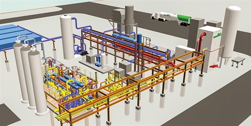
For ssLNG, modules of various capacities and functions have been developed. These modules can be combined to provide a plant that is well suited for an individual project while achieving a short schedule. FIG. 4 shows a typical plant layout, using prefabricated modules.
 |
|
FIG. 4. Typical ssLNG plant layout with prefabricated modules. |
To achieve the full benefit of standardization, a comprehensive execution strategy including engineering, procurement and construction must be developed. This strategy is proven to result in reduced handoffs, improved plot utilization and fewer interfaces among the various entities, leading to more efficient execution and lower project risk.
Operating considerations. Many of the first ssLNG plants were peakshaving facilities, which liquefy and store natural gas for approximately 50%–80% of the year. This ensures adequate gas availability when demand exceeds nominal pipeline supply for short durations (typically less than 2 wk/yr). As a result of their intermittent operation, there was less emphasis on reliability and efficiency. Today, with the expanding use of LNG for year-round and immediate use, the priorities shift from solely low CAPEX to include reliability and efficiency. This brings a need for innovative processes, products and equipment strategies.
One item to consider is that although ssLNG plants are significantly smaller than a baseload facility, they are still reasonably large and complex facilities. There is a significant scope and equipment count when all systems are included:
- Acid gas removal (typically CO2 and sometimes sulfur)
- Dehydration
- Mercury removal
- Liquefaction unit
- LNG storage
- Loading station.
Skilled operating staff is needed to operate an ssLNG plant. Using a simpler and less complex liquefaction unit, such as a gas expander cycle, can reduce the demands on the operating staff.
It can be tempting to remove apparently excess instrumentation to reduce CAPEX. However, this can be a false economy. To ensure proper operation, the plant must be adequately instrumented to supply the operating staff with the information needed to run the plant, particularly when the plant is not operating at the design point, e.g. during a plant upset or startup. Proper instrumentation can also greatly aid in optimizing the operation, because proper information is necessary for peak performance. Proper instrumentation can supply data for data analytics, which can greatly improve operating performance.4
Machinery. Baseload LNG plants require large, complex refrigerant compressor strings. Small-scale LNG has a lower mass flow and power consumption, allowing smaller, simpler refrigerant compressor arrangements. These arrangements can be either inline or integrally geared compressor arrangements. In the LNG industry, integrally geared compressors are well referenced up to 30 MW (up to 0.5 MMtpy or 1,500 tpd of LNG) in SMR and N2 gas expander service. Integrally geared compressors have been widely used in the air separation industry for many years, with thousands of installations in high-reliability services. Both integrally geared and inline configurations offer benefits depending on specific project requirements.
The primary benefit of the integrally geared compressor design is higher efficiency than inline compressors. The higher efficiency comes from lower inlet losses from the axial inlet design (compared to the radial inlet design of an inline compressor) and the ability to operate each compression stage at its optimum speed. With an extensive installed operating base, traditional inline compression arrangements offer some advantages over integrally geared compressors:
- The mechanical and rotor-dynamic design is less challenging. Integrally geared compressors require multiple high-speed pinions and gearing. The multi-pinion design requires additional bearings and seals.
- Reduced instrumentation to monitor, control and protect the compressor.
- Easier maintenance, particularly vertically split barrel configurations with ready access to the bearings and seals. Major overhauls can be completed more quickly due to easier bundle removal and reinstallation, and process piping typically does not need to be removed.
The site cooling medium should be considered when choosing between an integrally geared compressor and an inline compressor. It is natural to put an intercooler on each stage of an integrally geared compressor, because each stage is in its own casing. When water is the cooling medium, the intercooler can be close-coupled to the compressor, and the short piping runs reduce pressure drop and power consumption. However, if air cooling is used, then the intercoolers are located farther from the compressor, and the power benefit of extra cooling can be lost due the extra pressure drop in the piping.
Large baseload plants have traditionally used heavy-duty frame gas turbines or large API 612 multistage steam turbines as compressor drivers. In ssLNG, the smaller compressor arrangements allow electric motors, light-duty industrial gas turbines or steam turbine drivers. Several factors influence the selection of the driver type:
- High-reliability electric systems make electric motors a good choice.
- Using excess or non-liquefiable gas streams favors light-duty industrial gas turbines. Several small-scale LNG facilities have been in operation for many years with small gas turbine drives.
- Steam turbines are typically used only when steam supply already exists, due to the high CAPEX and operating complexity of a dedicated steam system.
One area that is common between baseload LNG, air separation and ssLNG is that the refrigeration compressor is a critical component of the liquefaction facility in terms of capital cost and overall facility performance. Drawing from experience in air separation, one area where lower facility costs can be realized is through standardization of the refrigeration compressor. If the liquefaction process is the same for various plant sizes, then CAPEX can be reduced by standardizing on the following items:
- General arrangements with common piping layouts and nozzle sizes
- Process instrumentation and controls, allowing for the common process and instrumentation diagrams (P&IDs)
- Auxiliary systems, such as lube oil systems and seal systems.
To allow for project-specific requirements, key internal components of the compressor are engineered, such as stage inlets, impellers, diffusers and return passages. These optimize the compressor aerodynamic performance and efficiency without changing the compressor external connections or overall plot plan.
When developing standardized offerings, it is critical to balance customer-specific machinery specifications, industry specifications and supplier standard designs. An ASU industry practice that can be adopted for ssLNG is to purchase compressors that do not comply fully with API 617 (axial and centrifugal compressors and expander-compressors). The best ASU operating and maintenance practices typically achieve greater than 98% availability, including planned outages for maintenance; this performance is available for ssLNG liquefiers.
For a low-cost, standard compressor configuration, it is important to understand supplier standards. As an example, during a standardization effort attempting to reduce cost, a machinery supply scope deleted certain auxiliary equipment and instrumentation. In discussing these deletions with the compressor suppliers, it was discovered that removing items actually added cost to the compressor package, as it required suppliers to remove items from their standard offerings. This shows that open discussions with compressor suppliers will give a low-cost solution.
Pre-treatment. Impurities present in the natural gas feed gas, such as CO2, water, heavy hydrocarbons and nitrogen must be removed for the following reasons:
- Meet LNG heating value specifications
- Prevent freezeout in the liquefaction equipment
- Recover NGL and/or condensates, which can be sold as valuable byproducts
- Recover heavy hydrocarbons to supply the required refrigerant makeup.
Small-scale LNG plants typically take their feed from a common carrier pipeline, whereas baseload LNG plants are fed from a single (or just a few) dedicated gas fields. Pipelines have different feed compositions, which can vary significantly and unpredictably over time. Therefore, ssLNG requires heavy hydrocarbon removal processes that can operate under changing ambient conditions and gas compositions.
Removing these impurities can involve many pieces of equipment that require higher capital cost and are more complicated to operate. It is challenging to balance operational flexibility with low plant complexity. It is also important to balance plant fuel demand with process offgas from the pretreatment system to reduce flare and operating costs associated with managing the tail gas.
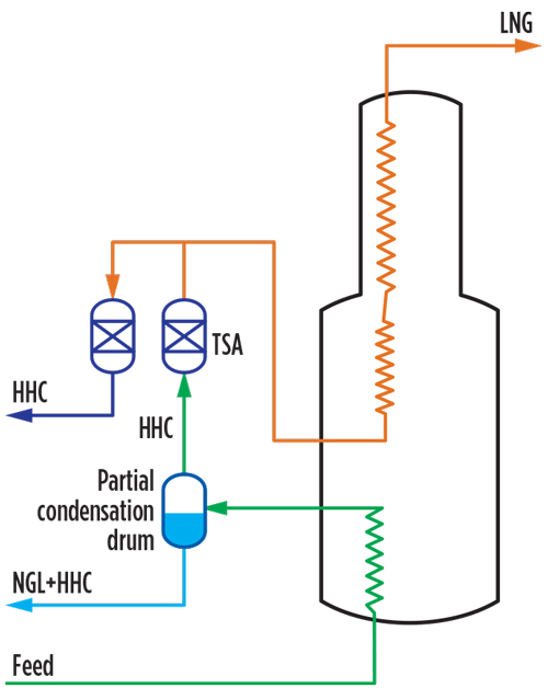
One recent innovation for heavy hydocarbon removal combines the benefits of thermal swing adsorption (primarily removing C8+ and aromatics) with partial condensation (removing residual C6 and C7).5,6 FIG. 5 shows such a combination integrated with the liquefaction process, which offers maximum operational flexibility and ensures efficient operation over the entire range of expected feed compositions. This configuration has been implemented and proven to be highly efficient, robust and flexible with varying feed gas compositions with acceptably low cost.
 |
|
FIG. 5. Integrated heavy hydrocarbons removal. |
This heavy hydrocarbon removal scheme allows the liquefaction system to operate at high efficiency, regardless of changes in the feed gas composition. This is very important in reducing power consumption and operating cost. When the feed gas is lean, the system primarily relies on the temperature swing absorption (TSA) unit to remove all heavy hydrocarbons without the need to lower feed gas pressure, thereby maintaining high liquefaction efficiency. When the feed gas is rich, the TSA will remove all the low-solubility heavy hydrocarbons, while the partial condensation will remove the relatively higher-solubility heavy hydrocarbons, such as C6 and C7, to acceptable levels to prevent freezeout. This again allows the liquefaction system to operate at high pressure and decreases the size requirement for the TSA bed. The recovered condensation stream from this process can be stabilized to produce LPG, NGL or gasoline byproducts, further increasing the revenue of the plant.
As demonstrated by the range of offerings and optimizations for even small-scale LNG facilities, engaging the liquefaction technology and equipment provider early in the project development stage can provide large benefits. Collaboration during the conceptual and pre-front-end engineering design (pre-FEED) phases allows the highest probability of executing a successful project in terms of cost, schedule, management of risk, meeting customer needs and profitable returns. GP
LITERATURE CITED
- Schmidt, W. P., C. M. Ott, Y. N. Liu and W. A. Kennington, “How the right technical choices lead to commercial success,” LNG 16, Oran, Algeria, 2010.
- Chatterjee, N., L. S. Gaumer, J. M. Geist, “Operational flexibility of LNG plants using the propane precooled multicomponent refrigerant MCR process,” LNG 5, Dusseldorf, West Germany, 1977.
- Dally, J., C. Butler, W. Miller, W. Schmidt and J. Styer, “Coil wound heat exchanger design for an evolving market,” Gastech 2018, Barcelona, Spain, September 2018.
- Barr, B., R. Pearsall, J. Bronfenbrenner and M. Hassan Al-Mohannadi, “Maximising LNG revenue by operating at peak performance,” Gastech 2015, Singapore, October 2015.
- Chen, F. and C. Ott, “Lean gas,” LNG Industry, January/February 2013.
- Schmidt, W. P., F. Chen and C. Ott, “Advances in removing heavy hydrocarbons from LNG liquefaction feed gas,” Gastech 2018, Barcelona, Spain, September 2018.
 |
Joseph Voda joined Air Products in 2009 and has held positions of increasing responsibility, including the role of Business Development Manager in the LNG Equipment and Technology Organization, which has responsibility for strategic initiatives, development of solutions for emerging LNG markets, marketing and account management. Mr. Voda earned a BS degree in mechanical engineering from Pennsylvania State University and an MBA degree from Lehigh University in Bethlehem, Pennsylvania.
 |
Fei Chen is a Commercial Manager for Air Products’ LNG Business. He holds a PhD in chemical engineering from Massachusetts Institute of Technology (MIT) and a minor in finance from the MIT Sloan School of Management. He joined Air Products in 2009 and has held various positions within the Chief Engineer’s Office, the Energy Technology group and the LNG Process Technology group. His responsibilities have included process design, cycle development, safety, plant startup and troubleshooting, as well as dynamic simulation and optimization of LNG plant operability and control schemes. Dr. Chen has been involved in many LNG projects across the world, which have encompassed a wide range of production scales and diverse process cycles. Dr. Chen holds five U.S. patents in natural gas processing and liquefaction.
 |
Adam Garcia is the Manager of Air Products’ LNG Product Development Team. He graduated with a BS degree in mechanical engineering from Lehigh University. He has worked for Air Products since 2004 in a number of plant design and project engineering positions. Before joining the LNG team in 2018, Mr. Garcia was the Cold Box Engineer and Design Manager for LNG, HyCo and Air Separation. In addition, he held responsibility for supporting modularization best practices and application on new business development. His major responsibilities presently include the development of Air Products small-scale and mid-scale standard LNG plants.


Comments