
Behavior and effect of methanol in amine treating systems
To prevent the formation of hydrates, methanol is commonly added to wellhead gas before it enters pipelines for transport to processing units. Perhaps under the mistaken notion that more is better, copious amounts of methanol are sometimes added, amounting to many tons of methanol per day. Almost invariably, a large proportion of the methanol is removed from the gas in the amine unit, where it tends to build up to high levels in certain areas, especially the amine regenerator.
Eventually, the absorbed methanol finds its way at high concentrations into the acid gas entering the sulfur plant, where it acts as a diluent. This absorbed methanol can significantly lower flame temperatures in the furnace, and it has a deleterious effect on Claus unit catalyst performance. However, not all the absorbed methanol is stripped from the solvent in the regenerator; a sizeable part remains in the lean solvent, which returns to the top of the absorber and sometimes causes high methanol levels in the treated gas.
NGL produced from the treated gas sourced from shale plays often contain large ethane and propane fractions. These fractions are used as cracker feeds for production of ethylene and propylene. Methanol is a serious poison to cracking catalysts; in fact, crackers sometime specify zero methanol content in ethane and propane feedstocks, despite the physical and economic impossibility of total removal.
Enterprise Products operates 15 NGL fractionation trains throughout the US. This article reports operating data collected by Enterprise Products from one of these trains. The liquids in the train are first amine treated in separate mixer-settler units to remove residual acid gases, mainly CO2. Spent amine is regenerated in conventional regenerators. Samples were analyzed by Enterprise Products and by Dow Chemical. Comparisons between simulated and measured methanol levels in various locations in the plant are included. Finally, recommendations are made to alleviate methanol contamination problems in fractionation train products.
Introduction. Hydrate inhibitors used in the gas industry are either methanol or a glycol, such as monoethylene glycol (MEG). Methanol is quite effective at preventing the formation of gas hydrates. It is usually injected at the wellhead, where it mixes with the gas. As the gas flows along a subsea pipeline, for example, it cools (typical seafloor temperature is about 39°F) and free water can start to form, depending on the pressure. At such a temperature, and above a pressure of approximately 300 psia, hydrate formation is almost assured. As the water condenses, methanol dissolves into it. With a high enough methanol concentration in the water phase, gas hydrates cannot form.
Pipeline plugging must be avoided at all costs. Perhaps for that reason, grossly excessive amounts of methanol are sometimes used as a measure of absolute assurance. Apart from the unnecessary cost associated with high use, none of the added methanol will go away on its own. Except for the methanol that is retained as high concentration levels in separation equipment, such as absorbers and solvent regenerators, the rest ends up in feed streams to various units and product streams from others.
In ethane and propane fractions, methanol plays havoc with catalysts in crackers. In conventional treating of sour gas, it negatively affects furnace and converter performance in sulfur plants. It is important to keep methanol usage in check at the wellhead, so that it can be removed before it enters processing units. Only a few tens of ppmv of methanol can poison the cracking catalysts used to convert ethane and propane to ethylene and propylene.
Ethane and propane can be cracked to ethylene and propylene either thermally (750°C–900°C) or catalytically (typically 500°C), using a zeolite or other catalyst. Catalytic cracking is done at lower temperatures because it saves energy; however, unlike thermal cracking, catalysts are sensitive to, and poisoned by, certain impurities. In particular, methanol is a known catalyst poison. For this reason, ethane and propane fractions intended for cracking have stringent limits on allowable methanol content.
This article presents the result of a performance analysis of the CO2 removal system of a fractionation train operated by Enterprise Products. The analysis was carried out using a proprietary mass- and heat-transfer-rate-based simulator. Data were collected by Enterprise, which also performed many of the stream composition analyses. Other stream analyses were carried out by Dow Chemical. Some of the simulation results suggested that the contactor performed as less than a single ideal stage, and that some carryunder of hydrocarbon into the rich amine from the contactor had likely occurred. Overall, simulation results compared remarkably well with measured performance data.
 |
|
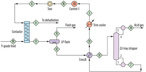
FIG. 1. Schematic of CO2 treater. |
Amine treating unit. The amine treating unit is shown schematically in Fig. 1. The contactor is an inline static mixer (also known as a motionless mixer) fed by the combined flow of Y-grade NGL feed and the diethanolamine (DEA) solvent used for treating. This is followed by a separator-coalescer, which splits the mixture into organic and aqueous phases. The treated liquids pass to a dehydration unit while the CO2-rich amine is regenerated in a conventional reboiled stripper. The fate of the methanol is the remaining question.
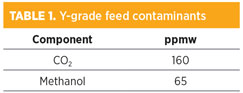 |
Table 1 shows the composition of the NGL feed. In addition to residual CO2 not removed in the original gas treatment step before transport to the fractionation plant, the NGL contains 65 ppmw of methanol, which comes from the methanol injected into the wellhead gas to prevent hydrate formation. Flow was measured at 3,310 bph. The methanol concentration rivals the CO2 concentration in the Y-grade feed.
The solvent concentration is held within a certain range; it was 25.4 wt% DEA as analyzed for this work. It contains 1.25 wt% heat-stable amine salts (HSAS). In DEA systems containing anything but the smallest CO2 loading, HSAS have no effect on treating per se, although they may cause corrosion of carbon steel. The foaming tendency of the lean solvent was classified by Dow as severe. The lean amine was reported to contain 0.92 wt% methanol.
The regenerator column had 22 conventional, valve-type trays operating at approximately 22 psia, with solvent feed to the top tray at 195°F (90.5°C). The reboiler used hot oil and had a known duty.
Simulation. Initial simulation work was performed on the assumption that the static mixer-separator combination acted as a single ideal stage of contact. At all times, however, the regenerator was simulated on a strictly mass-transfer-rate basis, in which methanol and CO2 stripping were directly determined by their mass-transfer rates and not through any kind of ideal stage calculations. The treated NGL composition was simulated to contain less than 1 ppmw of CO2 and only a few ppmw of methanol, in disagreement with the measured composition of 40 ppmw–60 ppmw of CO2 and several tens of ppmw of methanol.
Enterprise suggested that the static mixer-settler unit was performing with an efficiency of far less than 100%, and that the rather high residual levels of CO2 and methanol were a result of this inherent inefficiency. In line with this assumption, an efficiency of roughly 60% was found to reproduce the measured treating levels almost perfectly for both components. The primary reason for the low efficiency was the very small amine flow relative to NGL (NGL to amine volumetric flowrate ratio of greater than 10). The interfacial contact area is necessarily small, making good mass transfer much harder to achieve. This small amine flow, combined with the unusually low CO2 level in the NGL feed (resulting from the high amount of ethane rejection in the field), caused lower efficiency of contact.1
One of the interesting learnings from the simulation is that both residual CO2 and the more problematic methanol levels can be considerably reduced by improving the efficiency of contact with the amine. It does not take a large inefficiency to yield much poorer product quality than can be achieved. More intense mixing—achieved by using longer mixers or multiple units, or by redesigning the mixer—may be a way to encourage significant improvement.
On the other hand, more intense mixing may emulsify the hydrocarbon and amine phases, making phase separation more difficult. A balance must be struck. Yet another alternative is to recycle part of the amine back to the contactor so that a better volumetric flow ratio of NGL to amine can be achieved and the interfacial contact area can be increased.
The simulated flash gas rate was several times lower than measured. Simulation was done on the assumption that the phase separation in the settler was 100%. In liquid treating, the presence of a rag layer at interfaces and the difficulty in perfectly removing very fine droplets of one phase from another are well known. When the simulation was rerun with approximately 0.07% entrainment of NGL into the amine, the simulated and measured flash gas make rates coincided, as did the methanol content of the flash gas.
Entrainment of hydrocarbon into the solvent hardly affects treating; however, it can have a significant impact on flash gas rates, and it represents an avoidable2 loss from the product stream. At the levels present, there may be some impact of the methanol itself on the solubility of other hydrocarbons in the amine. Previous studies by the GPAa,b were conducted with much lower levels of methanol.
At this juncture, all other simulated performance parameters were found to be in excellent agreement with measured data. Simulated methanol in the lean amine and the lean amine loading agreed with measured data. Methanol, CO2 and total flowrate of the acid gas stream from the regenerator were also in excellent agreement.
Note: A mix-up occurred between the reflux and lean amine samples, and the laboratory analysis of stripper reflux was reported as 0.7 wt% methanol. However, the concentration predicted by the simulation was 16 wt%—a large difference. The reflux water was resampled and reanalyzed, and was then found to contain 17 wt% methanol, in almost perfect agreement with the simulation.
The fate of methanol. In a single stage of high-efficiency contact, virtually all the CO2 and most of the methanol can be removed by amine treating. Contactor inefficiencies, however, will result in significant loss of product quality, with an unnecessarily large fraction of the methanol in the feed remaining in the product stream.
Flash gas make (via pressure reduction in the flash drum) can remove only 1% or less of the methanol from the system, so it is not a significant outlet for methanol. Rather, it is a way to remove hydrocarbons from the amine before they enter the regenerator. Most of the methanol leaves with the gas from the regenerator; however, the lean amine recirculates a substantial flow of methanol compared with the flowrate of methanol entering the system with the raw feed—i.e., a substantial amount of methanol becomes trapped in the recirculating amine flow. The use of hot stripping gas in the flash drum may offer a way to improve the quality of the treated NGL.
The concentration of methanol in the reflux water is very high. This may offer an explanation for methanol trapping, as the condensate from the overhead condenser returns a significant amount of methanol to the regenerator, along with the condensed water. This makes it difficult for methanol to get out of the system until it builds a substantial concentration in the regenerator, including in the rich amine to the regenerator. Methanol is returned to the lean amine stream and prevents the treated NGL from achieving very low methanol levels. Note: High methanol levels in reflux water may also present the opportunity to remove methanol from the system via blowdown, in the same way ammonia is blown down in refinery amine systems.
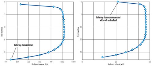
Methanol distribution in the regenerator. Figs. 2a and 2b show the simulated methanol distribution across the 22 trays in the regenerator in both the liquid and vapor phases. Each point refers to the stream leaving the tray. In the vapor phase, the mass flowrate of methanol is shown, rather than its vapor phase concentration, because the condensation of water causes concentrations to change, obscuring the process that is happening. However, only near the bottom of the regenerator does methanol strip from the solvent in a significant way.
 |
|
FIG. 2. Vapor and liquid distribution of methanol in regenerator. |
Equilibrium is reached quickly, as methanol strips from the solvent over the last few bottom trays. Near the top of the regenerator, the methanol vapor flow and liquid concentration both drop again—now because of the reabsorption of methanol into the cooler solvent on and near the feed tray.
In other situations with much lower levels of methanol in the stripper feed, similar behavior was predicted in the streams flowing between the feed tray and the top of a regenerator—i.e., in the reflux section.3 The methanol flow returned in the reflux is almost as large as its flow entering through the main recirculating solvent stream. Reflux returns 99% of the methanol from the overhead vapor, so the condenser is a serious trap for methanol.
At the levels seen in the regenerator, methanol is well beyond a minor contaminant. It is possible that significantly high methanol levels in the treating solvent might drag additional hydrocarbons into the amine and, as a result, contribute to foaming. Research into this question could be valuable to the industry.
Summary. Significant methanol removal from NGL can be achieved by extraction into the lean amine used for CO2 removal, but it performs best with high-efficiency contacting. Methanol is difficult to squeeze from the treating system because of its high affinity for water; however, mass-transfer-rate-based simulation can predict the performance of the CO2 removal system, including the distribution of methanol in the unit.
Mass-transfer-rate-based simulation also reveals an interesting aspect of the methanol distribution in the regenerator; the regenerator struggles to remove absorbed methanol because the overhead condenser returns so much of it to the tower. This suggests that a possible way to remove more methanol from the entering NGL is to operate the condenser at a considerably higher temperature than in a conventional regenerator. In this way, less methanol might be recirculated back to the contactor. Across the bottom seven or eight trays, methanol is readily stripped; however, as vapor flows up the tower, equilibrium is soon reached. Methanol removal in the regenerator is also difficult for this reason and causes a high concentration in the recirculating solvent.
One way to remove a large fraction of methanol from the system is to blow down a substantial fraction of the reflux water. This stream contains 16%–17% methanol and represents nearly as high of a methanol flow as the methanol entering with the rich amine feed itself. Returning it to the stripper, rather than removing it from the system, can be considered a waste.
The presence of methanol in the regenerator, even at such high levels, is not expected to significantly impact the system’s ability to remove CO2. However, the methanol does affect the regenerator’s hydraulic capacity because the vapor volume is 10% methanol (i.e., the vapor has a 10% higher flowrate than in the absence of methanol). As a result, tower capacity can also benefit from reflux blowdown. The most important factor is that high methanol in the regenerator negatively affects the system’s ability to remove methanol. GP
Literature cited
- Ng, H.-J. and H. Schroeder, “Vapor-liquid equilibrium studies on water-methanol-MDEA-hydrocarbon systems,” Gas Processors Association, Tulsa, Oklahoma, April 2003.
- Courtial, X., E. Booneart, A. Valtz, P. Theveneau, P. Stringari and C. Coquelet, “Methanol distribution (as a contaminant) in fractionation products and freeze-out boundaries,” Gas Processors Association, Tulsa, Oklahoma, March 2013.
- Govindarajan, A., N. A. Hatcher and R. H. Weiland, “Methanol distribution in amine systems and its impact on plant performance,” AIChE spring meeting, Austin, Texas, 2015.
Notes
a High initial CO2 means that a larger fraction can be removed more easily, although it may still not be possible to reach truly low residual levels in the treated NGL stream.
b As an example, mesh coalescers can effectively prevent entrainment of either phase into the other.
 |
Ralph H. Weiland is a PhD graduate in chemical engineering from the University of Toronto in Canada.
More than 25 yr ago, he formed Optimized Gas Treating, and with Australian colleagues developed the ProTreat mass-transfer-rate-base gas treating simulator. Dr. Weiland also developed the sulfur plant simulator SulphurPro. He is presently the President of Optimized Gas Treating.
 |
Albrecht (Al) Goethe is Senior Director of Process Engineering at Enterprise Products Operating LLP. He oversees the execution of capital projects and the application of process technology. Mr. Goethe has 37 yr of process experience focused on the midstream industry and is an active member of GPA Midstream Association’s Research Committee.
He received a Diplom Ingenieur from RWTH Aachen University in Germany and an MS degree in chemical engineering from Rice University in Texas.
 |
Rich Ackman is the Technology Leader for Dow Oil and Gas, based in Houston, Texas. He has more than 25 yr of experience in UCARSOL specialty amine applications and amine plant design, as well as plant troubleshooting and problem-solving. Mr. Ackman holds degrees in chemistry and chemical engineering from the University of Pittsburgh in Pennsylvania.


Comments