
Adjust treatment strategies to resolve methanol issues and meet pipeline specs
It is not uncommon for producers to introduce methanol into their hydrocarbon systems as a means of hydrate inhibition, as an additive blended with H2S scavengers, or for other purposes. While much of the methanol is recovered in liquid knockout drums, a portion of it remains in the natural gas or NGL, where it eventually makes its way to downstream processing units.
The presence of methanol can have negative consequences for gas processors, such as penalties by pipeline operators for excessive methanol in NGL feeds, problems meeting propane quality specifications in fractionation units, or regulatory issues from methanol emissions.
If a reduction of the methanol content in hydrocarbon streams is desired, it can be done with an aqueous wash stream, such as those found in amine sweetening units. Methanol will be initially removed by the aqueous amine, but it will steadily accumulate in the amine sweetening unit until some equilibrium is reached, after which time the methanol escapes in both the sweetened gas and the acid gas.
Several options are available to the operator when confronted with methanol in amine units. The correct solution depends on the needs of downstream processes. The methanol can be removed almost entirely through a purge of the regenerator reflux stream. These and other strategies are evaluated with a process simulator, the results of which are compared to vapor-liquid equilibrium and operational data.
In practice, a purge of the liquid reflux to the regenerator is an excellent means of providing an outlet for the methanol. Purge rates and disposal options are evaluated, along with the possibility of recovering the methanol as a product for reuse.a
Addressing methanol issues. In recent years, more and more attention has been paid to methanol use in the oil and gas industry. It is a common component utilized for a variety of purposes, and one that has been in use for decades. However, its use, or overuse, is beginning to cause issues for midstream processors as they struggle to meet new NGL product specifications.
Historically, little attention has been paid to the presence of methanol in upstream and midstream facilities. Methanol enters a plant with inlet gas or is injected directly within the process, concentrating in the recovered NGL product with trace amounts present in the residue gas, depending on the process. The methanol then follows propane through fractionation, presenting a challenge for downstream customers as propane demand shifts away from fuel and into petrochemical markets.
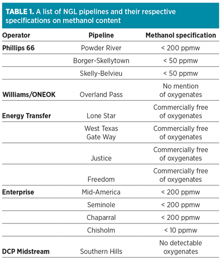
To that end, NGL shippers, which were not historically concerned about methanol, have begun imposing stringent methanol limits and levying penalties on producers for barrels found to be out of compliance. Typical pipeline specifications for methanol are listed in Table 1.
 |
Sources of methanol. While methanol is a very common component found in the oil and gas industry, it is not a naturally occurring component of petroleum. Its presence is entirely due to its intentional addition into natural gas and liquid streams. Methanol can enter a midstream facility in various fluid phases and from various sources. Understanding what these sources are can be instrumental in forming a complete plan to prevent it from ending up in the finished products.
The primary use for methanol in this industry is hydrate inhibition, a topic that has been well studied.1 Hydrates are solid crystalline structures that form from a combination of water and hydrocarbons. The formation of hydrates has negative effects on operations, such as plugging of piping and valves, and other safety issues. Once formed, it is often necessary to shut down operations to allow equipment to warm up—a situation that could cost the producer considerable time and money. Inhibiting the formation of these solids is, therefore, quite important.
Hydrates formation is primarily influenced by temperature. As a result, methanol injection is most often used in the winter, creating a peak “methanol season” that most operators define as the period between October and February. Since methanol is also a common carrier solvent, it is present outside of the methanol season. It peaks during winter operations and subsides through the summer, although it may always be present.
In general, industry has become complacent with regard to methanol injection, deferring to the most conservative mode of operation to reduce exposure to downtime and callouts. In 2015, the average cost of methanol was $1.50/gal, although the total cost factors in items such as handling, disposal and potential off-specification penalties on the order of $1/bbl.
Recognizing that the use of methanol has become excessive, operators have begun curtailing usage even prior to the enforcement of NGL specifications. For example, timing injection coincidental with plunger operations, as opposed to simply keeping injection on while the well is not producing, helps curtail excess methanol usage.
Tools2 are available to accurately predict hydrate inhibition with methanol, from which the optimal amount of methanol to use can be calculated. Such optimizations have been done with success.3 Simulating the system could help considerably reduce the use of methanol, helping producers avoid penalties and the additional cost of the excess methanol. With the correct amount of methanol known, producers can still be conservative in their use of inhibitor, without using significantly more methanol than required.
Path of methanol through a midstream facility. Understanding the route that methanol takes through a gas plant can be helpful in developing strategies for its removal. When it arrives at the inlet knockouts, it can typically be found in all three phases of the plant feed.
While some of the inlet methanol is removed at the front end of an NGL plant, enough can carry through in the hydrocarbon phases to violate pipeline NGL specifications. A good model is required to accurately predict the distribution of methanol within a recovery process, accounting for polar and non-polar properties of methanol.
For this study, a Peng-Robinson polar equation of state was used to demonstrate the distribution of methanol between the vapor, hydrocarbon liquid and aqueous liquid phases at the plant inlet. For systems containing amine solvents, an electrolytic ELR package was used in combination with the Peng-Robinson polar package. The results from this package are compared to data from GPA Research Report (RR) 1494 and shown in Table 2.
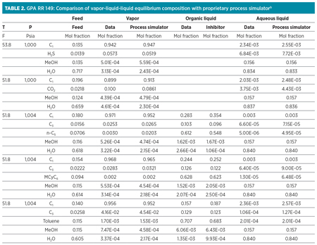 |
As can be seen from these data, the methanol present in the inlet vapor is significant enough that, when concentrated in the NGL stream, it can create off-specification products. Liquid hydrocarbons entering the plant can also contain significant quantities of methanol—as much as 3–7 vol%.5 Liquids collected at the front-end knockouts are typically stabilized, and the overhead vapors are routed back to the NGL recovery plant for processing, carrying methanol with them. Both the inlet vapors and inlet liquids can be a source of methanol feeding into the gas plant.
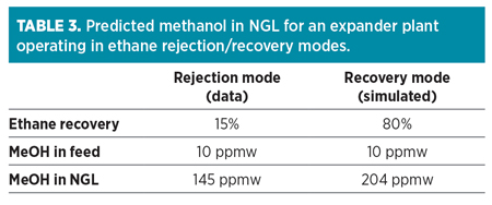
Once the methanol enters an NGL recovery process, it generally follows the NGL through the process, as can be seen in Anadarko’s Chipeta Plant Train 2. Methanol is condensed in the demethanizer and exits with the NGL product, leaving only trace amounts remaining in the overhead residue gas. Models show this to be true, regardless of whether the process is operating in ethane recovery or rejection mode. The methanol concentration in the NGL product will be greater while operating in rejection mode, as the total volume of NGL will be less due to the reduction of ethane in the liquid product. This can be seen from the simulated results in Table 3.
 |
As the methanol will concentrate in the NGL product, even small amounts in the inlet vapor can push that product off specification. A block flow diagram showing the path of methanol through Chipeta’s Train 2 is shown in Fig. 1, with information on the concentration of methanol into product NGL.
 |
| FIG. 1. Block diagram for Chipeta Train 2 showing methanol concentration in NGL product, based on measured values. |
Once in the NGL product, the methanol travels to a fractionation train, where it primarily follows the propane, leaving trace amounts in ethane and butane, depending on the split. Evidence of this behavior can be seen for a representative analysis of fractionated products during the methanol season in Table 4, as well as in the GPA RR 219.6
In the entire flow of methanol from the wellhead to finished product, it is at the fractionation step where methanol finally becomes a true problem. The finished products, such as propane, must be essentially free of methanol if they are not being used as domestic fuel. The cost of removing methanol from the finished products is pushed back from the pipeline to the producers.
Keeping methanol out of products. Knowing that methanol is present in the feed and can concentrate to levels high enough to push products off specification, it is important for operators to develop strategies to keep methanol out of their finished products. In almost all cases, these strategies center on a wash of some type, by treating of either the inlet gas or NGL product.
While molecular sieves have the capacity to remove methanol, they are displaced by water and subject to breakthrough and carryover into the downstream process and are, therefore, not effective for feeds with an appreciable water content. Methanol removal from NGL with molecular sieves can also be problematic, as regeneration with natural gas introduces other equally detrimental contaminants—namely, methane and carbon dioxide.
In some cases, using the amine sweetening unit as a methanol removal unit has been successful. This option does not require additional equipment if the amine plant is already present, and if the amine solvent already has the capability of removing methanol from the sour gas or sour liquid. This strategy was put in place at Anadarko’s Chipeta facility. Chipeta’s Train 3 has a traditional vapor treatment system upstream of the cryogenic unit, while Train 2 has amine treatment for the NGL products. Diagrams of these configurations, as well as measured methanol concentrations, are shown in Fig. 2 and Fig. 3.
 |
| FIG. 2. Block diagram for Chipeta Train 2, showing methanol concentration in NGL product and its removal, based on measured values. |
 |
| FIG. 3. Block diagram for Chipeta Train 3, showing methanol concentration in NGL product and its removal, based on measured values. |
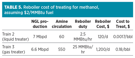
If evaluating the option between treating NGL for methanol removal or treating the gas, the most economical choice is to treat the NGL. The NGL itself is a significantly smaller stream as compared to the gas, and it will have a higher concentration of methanol. This allows the operator to treat the NGL with significantly lower circulation rates of amine, resulting in significant savings in terms of operation. Chipeta’s Train 3 treats the gas before processing and uses 550 standard cubic meters per hour (sm3/hr; or standard grams per minute, sgpm) of circulation. Meanwhile, Train 2 treats with 60 sgpm of circulation after processing, as can be seen in Table 5. Methanol removal from the NGL can be 10 times cheaper than treating the gas.
 |
With some cost involved, treating with amine solutions can be an effective means of removing methanol in the vapor or liquid phase, as was done at the Chipeta facility. However, some operational changes to the amine unit may be required. If the amine unit is operated “normally,” then methanol can accumulate in the amine solvent to the point that the system loses its ability to remove methanol to sufficiently low quantities in the treated product.
As methanol has a polar character and a high affinity for water, it will be removed at first by the aqueous amine in the contactor and then stripped out in the amine still. However, most of the methanol leaving the still overhead will be condensed in the reflux circuit and returned to the system. This can cause an accumulation of methanol within the amine solvent loop, as shown in Fig. 4.
 |
| FIG. 4. Predicted buildup of methanol in amine loop for Chipeta Train 2 at various purge rates. |
Higher concentrations of methanol remaining in the lean amine will subsequently reduce the amine solution’s ability to deeply remove methanol from the treated vapor or liquid. The effect of methanol remaining in the lean amine can be understood using GPA RR 184,7 as described in Table 6.
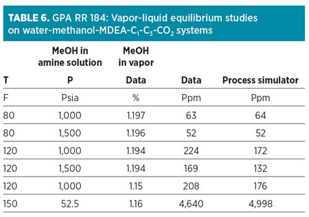 |
In addition to reduced treating capability, this methanol buildup can cause multiple operational issues for the amine unit itself, including excessive foaming and solvent loss,8 depression of the reboiler temperature and general dilution of the amine solvent if the methanol is allowed to build to significant concentrations. However, operational changes can be made to mitigate these issues.
To retain the amine unit’s capacity to recover methanol, as well as to avoid operational issues, some or all of the regenerator overhead reflux can be purged and replaced with fresh water. It is at this location in the facility where methanol is at its highest concentration and the amine portion of the liquid is at its lowest. The effect of this purge on both the methanol removal efficiency of the unit, and on the increased cost of makeup water, can be seen in Fig. 5 and Fig. 6. The makeup is typically inserted at the surge tank or still bottoms, as opposed to the still reflux. Without liquid entering onto the wash trays of the amine regenerator, an increase in solvent losses can be expected, increasing the cost of operations.
 |
| FIG. 6. Effect of purge rate on AGRU’s ability to remove methanol for Chipeta Train 3 (gas treater). Feed gas contains 10 ppmwt methanol. |
In addition to solvent losses, the increase in required makeup water itself can be a significant cost. While some facilities have access to relatively low-cost demineralized water, others, such as operators in the Rockies, pay as much as $0.4/gal. This additional cost is shown in Fig. 7 and Fig. 8.
 |
| FIG. 7. Increased cost of makeup water at various purge rates for Chipeta Train 2 (NGL treater). Cost assumes $0.4/gal of water and is compared to the same system with no reflux purge. |
 |
| FIG. 8. Increased cost of makeup water at various purge rates for Chipeta Train 3 (gas treater). Cost assumes $0.4/gal of water and is compared to the same system with no reflux purge. |
For Anadarko’s Chipeta facility, the choice was made for a full reflux purge (100%) for Train 2. This system has a relatively low circulation rate, and, therefore, a very low rate of reflux. Operationally, it was easier to simply set up a complete purge, as opposed to trying to return 0.5 spgm–1 sgpm back to the top of the column. Train 3, however, has a significantly greater circulation rate and a significantly greater reflux rate. Operations began with approximately 50% reflux purge. Assisted by simulation, operations began to back the purge down to balance the effective methanol removal with operating costs. For this train, the purge rate settled in the 10%–15% range. Doing so gave approximately 1 ppm–2 ppm methanol in the treated gas overhead. Once through the gas plant, this methanol concentrated in the NGL to less than 50 ppm, well below the 200-ppm pipeline specification.
At Chipeta, no sulfur recovery unit (SRU) was in use. However, if an SRU is present, a full water wash may make more sense. Methanol contains carbon in its molecular structure, and its destruction in the SRU burner can result in COS and CS2 formation. Non-combusted methanol can also cause issues similar to those caused by hydrocarbons across catalyst beds.
An amine system or a water wash can be used to remove methanol, but it does not mean that the products will be completely on specification. This is certainly the case when treating NGL. Treating the product NGL has the advantage of treating a smaller stream with more highly concentrated methanol. However, a negative effect is seen in that the hydrocarbons leave the wash saturated with water. NGL specifications typically include limits on free water, such as “no free water at 34°F.” This is the case with the Enterprise Mid-America, Seminole and Chaparral pipelines.
A common way of getting the NGL back on free-water specification is to chill the NGL and remove the water in a coalescer. In multi-train facilities, NGL treatment may be performed on only one or some of the trains, while other trains have methanol removal upstream of the cryogenic unit. If dry NGL is available to commingle with the wet NGL, then full water removal down to 34°F may not be required. The wet NGL may need to be cooled to only 40°F–50°F, depending on expected hydrate formation temperatures and available wet/dry volumes, so that the blended product is on specification. If a facility has only one train, or if all trains receive treatment of the NGL product, then deeper removal of water may be required.
Refrigeration down to lower temperatures, followed by liquid-liquid separation, can provide adequate water removal. After the wash, ethylene glycol is injected to inhibit hydrate formation, and the commingled liquid is refrigerated to 25°F–30°F. The immiscible phase (ethylene glycol, water and methanol) is removed from the hydrocarbon phase at a liquid-liquid coalescer with a 99.5% capture efficiency. NGL is injected into the pipeline, and the immiscible phase is routed to a regenerator, where ethylene glycol is reconcentrated to 80 wt% and returned to the system. While methanol could be recovered from the still effluent, it is typically routed to an incinerator for containment.
An alternative to refrigeration is dehydration via molecular sieve beds. While these beds can and do perform well in removing water from the NGL, care must be taken in the selection of gas used in the regeneration cycle. If the regeneration gas contains CO2, for example, the CO2 can build up on the bed during the regeneration cycle, only to be removed by the NGL during the water absorption cycle. The net result is an NGL that is now on specification for free water, but is no longer on specification for CO2.
Post-methanol removal. In most cases, when methanol is removed from the gas plant, it is in an aqueous solution. The next step in the methanol removal process is to address the options for disposal of methanol/water mixtures.
In some instances, methanol rates may be small enough to warrant simple offsite disposal of the contaminated water. While this may be the simplest method, as methanol quantities increase, other options become more attractive.
In large facilities with either water wash systems or large purges from amine units, methanol regeneration columns may be present. Multiple advantages exist to methanol regeneration columns. In some cases, their use can help mitigate the overall cost of methanol injection, as the methanol recovered from the hydrocarbons can be recycled for field use. Note: Use in a cryogenic process is not recommended, as operating temperatures require a level of purity not necessarily possible with anything less than an industrial-grade methanol plant. Concentrating the methanol could also convert it from a waste stream into a product stream, allowing its sale to nearby methanol users.
The methanol regenerator has an additional advantage in that the water required to wash out the methanol is reclaimed. This water can then be sent back to the amine system or water wash loop, thereby reducing the cost of the amine unit reflux purge.
Recommendations. As midstream operators have learned in recent years, methanol is a contaminant that cannot be overlooked. Even with a three-phase knockout at the front of the plant, methanol still enters with hydrocarbons. Depending on the requirements of the operator accepting the gas plant products, very small amounts of methanol in the plant feed can trigger costly penalties.
These penalties can be avoided in a variety of ways. Producers can take greater care in the amount of methanol they are injecting, reducing both their costs and the problem that methanol poses to processors. The processors themselves can either alter the operations of sweetening plants, or they can choose specialized treatment processes for methanol removal.
In most cases, a combination of these approaches will provide the most efficient removal of methanol. GP
Don O’brien is an Engineer with Anadarko Petroleum. He has 25 yr of operating experience in gas processing. He holds a BS degree in mechanical engineering from Colorado State University and is a licensed Professional Engineer in the state of Colorado.
Jesus Mejorada is an Engineer with Empire Gas Services. He has 10 yr of experience in process simulation and acid gas treatment technologies in the natural gas and refining industry. Mr. Mejorada has worked extensively on design and troubleshooting of amine processing plants. He holds a BS degree in chemical engineering from Texas A&M University.
Luke Addington is the Business Development Manager at Bryan Research
and Engineering LLC (BR&E). He holds a BS degree in chemical engineering
from Texas A&M University and is a licensed Professional Engineer in Texas. Mr.
Addington has worked in business development, consulting and training for BR&E
since 2005 in the US and in Europe.


Comments