
Supervise gas turbine speed and axial load to control exhaust temperature
Supervision and control of gas turbines are complex tasks that require expert experience. However, it is difficult to ensure the availability of experts at all times and at all sites.
This article proposes the building of an expert system, based on practical, cumulative experiences and system knowledge, to regulate and ensure the supervision and control of gas turbine variables. This system would enable the prediction of abnormal turbine operating scenarios, thereby reducing turbine downtime, limiting production losses and reducing maintenance costs.
Introduction. The complexity of the supervision of a gas turbine lies in the difficulty of obtaining a detailed mathematical model, as well as in the randomness and fluctuating behaviors of the variables to be controlled in this machine. During gas turbine operation, the monitoring system is provided to ensure its control and protection. However, a suitable monitoring system must be developed to monitor the gas turbine parameters and to achieve the necessary flexibility for meeting the different types of loads imposed on the turbine.1–3
Gas can be fired and burned only within a narrow ratio of air to fuel. The temperature is dependent on the percentage of intake air. On the other hand, if the speed of the gas turbine cannot be measured, then the amount of absorbed air cannot be measured with sufficient precision so that it can be used in the control of the exhaust temperature.4–6
This article proposes artificial intelligence techniques, based on the use of fuzzy logic, for the design and implementation of an intelligent controller for a gas turbine. A mathematical model based on thermodynamic variations is used to describe the behavior of a gas turbine to improve its operation.
Gas turbine supervision system. The performance of a gas turbine is influenced by the temperature of the intake air, which varies considerably during different seasons. This sensitivity to seasonal and temperature variation adversely affects the operation of the gas turbine.1,7–10 During proper gas turbine operation, increases in speed rate and exhaust temperature are limited to protect turbine components against excessive thermal and mechanical stresses.
Increases in acceleration and temperature are independently controlled by the closed loop of the temperature and speed control systems. These operating rates are limited by the control circuit, and the fuel control signals are sent by the control software launch. In addition, the software sets the maximum and minimum fuel stroke reference (FSR) and allows manual control of the FSR. Fig. 1 shows a simplified diagram of a gas turbine and its control system. Input and output signals include the rotational speed (N), the temperature of the absorbed air (T0), the exhaust temperature (TX) and the mechanical power. The gas turbine speed depends on the intake air and the gas volume.
Fuzzy logic is a suitable tool for building the supervisory control laws with the following objectives:
- Determine the fuel flow (the reference signal controlling the fuel flow FSR), depending on the rotational speed
- Obtain the exhaust temperature control over a range of ambient temperatures.
Overheating manifests in the increase in exhaust temperature (TExhaust). Beyond certain overheating limits, a destruction risk exists for the hot part, particularly the internal combustion chamber of the gas turbine, the nozzle of the gas turbine and possibly the moving blades of the turbine (Fig. 2).11
 |
|
FIG. 1. Control system of a gas turbine.
|
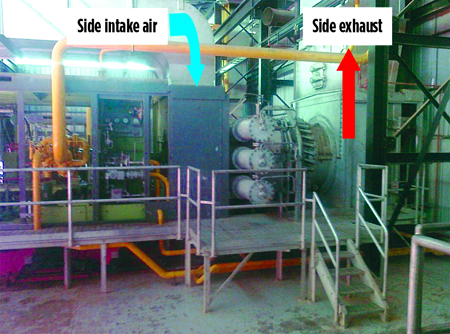 |
| FIG. 2. Gas turbine showing side intake air and side exhaust. |
Overheating is a more frequent occurrence at the startup stage due to startup anomalies—e.g., rapid acceleration can cause overheating. However, permanent overheating is possible if the efficiency of the compressor and the gas turbine are deteriorated. Therefore, the measuring and recording of TExhaust is classified for simple display, for alarm or to halt startup.
In any case, the cause of overheating must be uncovered if the startup overheating exceeds certain limits. The startup must be stopped, and the fuel accumulation in the combustion chamber must be purged.11–13 In this case, limits for TExhaust can be classified for simple display, for alarm or for shutdown.
The typical process flow of a gas turbine is shown in Fig. 3. In this study, the gas turbine supervision consists of three control loops:
- Room temperature control—i.e., temperature at the compressor intake, T1 = TA
- Turbine combustion chamber temperature control, TCC
- Turbine shaft rotational speed control, N.
Temperature and speed controls are activated during an abnormal operating state, where the maximum power of a gas turbine exceeds the operating limit, which depends on the shaft speed and the ambient temperature. A simplified representation of a gas turbine model is shown in Fig. 4.
 |
|
FIG. 3. Control variables of a gas turbine.
|
 |
| FIG. 4. Simplified representation of a gas turbine model. |
Controlling the temperature of a gas turbine limits the temperature of the exhaust gas by reducing the fuel flow, as the air flow decreases with the speed of the shaft. For a given gas turbine, the reference temperature is 513°C. The maximum temperature during the transition period should not exceed 80% above the reference temperature.
In Fig. 5, the evolution of the temperatures in the gas turbine is shown. The temperature due to air compression reaches approximately 115°C, and the outlet of the low-pressure wheel temperature reaches approximately 450°C.
The low-pressure compressor, the high-pressure compressor, the combustor and the high-pressure impeller (HPI) temperatures reach 115°C, 500°C, 1,200°C and 840°C, respectively.
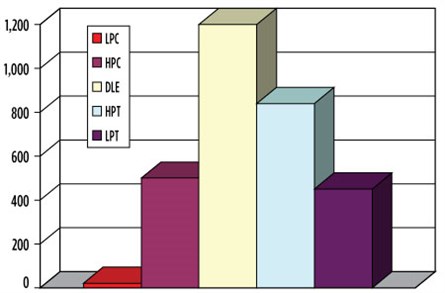 |
| FIG. 5. Evolution of the temperatures in various turbine components. |
Thermodynamic cycle of a gas turbine. The thermodynamic cycle is represented in a temperature vs. specific entropy (T–s) diagram, based on a Brayton cycle of temperature and shown in Fig. 6. The theoretical cycle gas turbine comprises: Input temperature, T1, which represents the compressor intake value T1 = TA; and the temperature (T2) representing the end of the isentropic compression. The gas temperature increases in the combustion chamber from T2 to T3, and the temperature value T3 is determined from the balance of the combustion chamber. In the last step, the gases expand adiabatically in the turbine (step T3 to T4). These transformations are expressed in Eqs. 1–4:
ΔW + ΔQ = ΔH (1)
WComb = M × CP × (T2 – T1) (2)
QComb = M × CP × (T3 – T2) (3)
WExpansion = M × CP × (T3 – T4) (4)
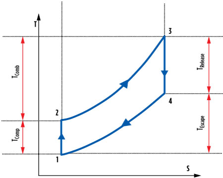 |
| FIG. 6. Diagram from temperature Brayton cycle. |
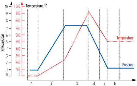 |
| FIG. 7. Temperature evolution in different parts of the gas turbine. |
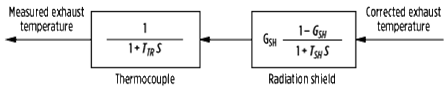 |
| FIG. 8. Exhaust temperature measurement block. |
Fig. 7 shows the temperature evolution in different sections of the gas turbine, from the temperature from air compression (approximately 115°C) to the temperature of the output wheel of low pressure (approximately 450°C).
Gas turbine variables control. The control of TExhaust is performed with a computer that receives signals from the 12 thermocouples (TC) distributed on the second-stage turbine blade. The computer interprets and compares different values, and then calculates the average temperature and sends it to the PLC.
When the input turbine temperature is high, the turbine blades become deformed. To limit T4, a temperature control is implemented. The output temperature of the power turbine is often used as a control variable because the measurement of T4 is difficult to obtain. Temperature control can be achieved by using a proportional-integral (PI) controller. The transfer function for this controller is shown in Eq. 5:
![]() (5)
(5)
The transfer function describing the characteristics of the thermocouples can be expressed as shown in Eq. 6:
![]() (6)
(6)
The exhaust temperature is expressed by Eq. 7. It is dependent on the reference temperature, the fuel and the initial speed.
![]() (7)
(7)
Temperature control can be achieved based on the control block presented in Eq. 8:
![]() (8)
(8)
As the compressor intake temperature increases, the specific compression work increases, while the air mass flowrate decreases due to a decrease in specific gravity. Accordingly, the turbine efficiency and the useful work (and, therefore, the power) decrease.
If the temperature decreases, the reverse scenario occurs. Fig. 9 shows an example of how power, specific fuel consumption and exhaust gas flow are influenced by the ambient temperature.3,10,14–20 The variation of the reference temperature, Tυ, depends on the fluctuation of the ambient temperature, TAmb.
 |
| FIG. 9. Influence of ambient temperature on the performanceof a gas turbine. |
For the shaft speed control, the difference setting mode is applied to the shaft speed control subsystem. A proportion control method is used in the proportional integral-derivative (PID) controller. It is reasonable to consider the controller as a control loop proportion of single control inertia. The transfer function is given in Eq. 9:
![]() (9)
(9)
The gas turbine torque characteristics are a function of the fuel flow, and the turbine speed is essentially linear, as described in Eq. 10:
![]() (10)
(10)
For acceleration control, the gas turbine can easily pack when its speed increases rapidly. However, the acceleration control is introduced to avoid such overspend. The temperature control and acceleration control of the subsystem are performed using a PI regulator. The transfer function is shown in Eqs. 11 and 12:
![]() (11)
(11)
![]() (12)
(12)
The fuel flowrates are the outputs for the three control subsystems. After selection by a minimum selector, the final result is used to control the parameters of the gas turbine. Under normal circumstances, the shaft speed control subsystem has the decisive effect. The temperature control and acceleration control are generally ineffective, except under special conditions.
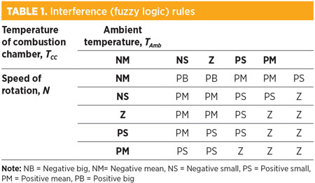
This article proposes the implementation of an intelligent controller for the gas turbine, based on fuzzy logic (Table 1).21–25 The fuzzy membership function structure of the selected controller is shown in Fig. 10. To achieve the proposed approach, a simulation model is required that is able to describe the behavior of the gas turbine to ensure the optimum behavior of the system under study. The gas turbine system has two variables—input variables and output variables:
- Input variables: The ambient air temperature (TA), combustion chamber temperature (TCC) and the shaft rotation speed of the gas turbine (N).
- Output variables: The fuel flow signals (DSC).
 |
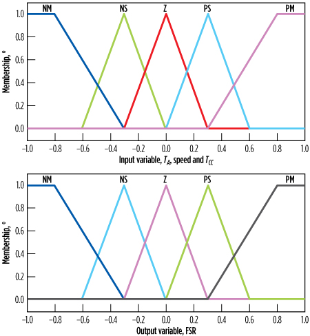 |
| FIG. 10. Membership function of different linguistic variables. |
Simulation results. Validation tests were performed to evaluate the performance and the capacity of the proposed control approach. Figs. 11–13 show the three-phase function of temperature. In these results, the DSC is adapted to the combustion system of the gas turbine for the application in different phases of operation (startup, overheating, acceleration and the normal operating conditions of a gas turbine) and under climate effects. Changes in the DSC from the temperature of the combustion chamber and the ambient temperature of the intake air, as well as from the shaft speed of rotation of the gas turbine, are shown in Figs. 14 and 15, respectively.
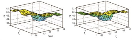 |
| FIG. 11. Change in working capital, according to the TCC and speed, with the variation of FSR function of TCC and TA. |
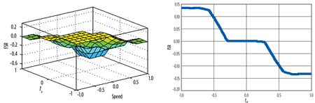 |
| FIG. 12. Variation of the FSR, depending on the ambient temperature and the speed of rotation, with the variation of the FSR function of the combustion chamber temperature. |
 |
| FIG. 13. Variation of the FSR, depending on the ambient temperature, with the variation of the FSR function of the shaft speed of rotation of the turbine. |
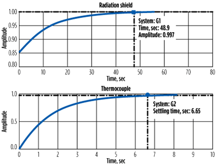 |
| FIG. 14. Radiation response of the shield and thermocouple. |
 |
| FIG. 15. Step response of the speed. |
Fig. 16 shows the temperature response of the exhaust gas speed and the fuel flow by IGV. The temperature reaches constant value at the steady state after the transitory period. The increasing value during the transient temperature does not exceed the thresholds of protection; therefore, the gas turbine does not come out of the operating mode during the startup stage.
From the control system used, it can be concluded that:
- During the initial startup period, the FSR is maintained at zero until it reaches the ignition speed and the purge of the gas turbine is completed
- The ignition FSR level is required and the ignition is applied
- After the heating period, the fuel supply to the gas turbine is gradually increased at a predetermined rate until the FSR reaches a fixed limit of acceleration
- As the gas turbine accelerates to reach the rated speed, the airflow increases to provide more fuel.
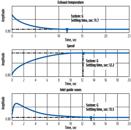 |
| FIG. 16. Response of the exhaust temperature, speed and IGV. |
When the FSR of the gas turbine is under speed control, the fixed limit of fuel is transferred from the level of acceleration to the maximum level. However, the FSR that is effectively applied is kept at the required level by the speed control system.
Takeaway. Fuzzy logic has been used to control the gas turbine at various stages of operation (launch, startup and acceleration) by the optimization of the FSR and the minimization of the energy absorbed by the gas turbine.
An increase in ambient temperature will slow the gas turbine operation. Its output can be increased by reducing the compressor intake temperature, which is achieved by introducing cooling air into the compressor. The temperature of the exhaust gas is also controlled by increasing the air flow.
Validation tests based on a fuzzy logic system improved the fuel demand of the FSR in the combustion chamber. Fuzzy logic control rules ensure the oscillation damping of the system response, with better recorded performance. GP
LITERATURE CITED
- Benyounes, A., A. Hafaifa and A. Daoudi, “Takagi Sugeno models identification based on fuzzy data construction: Gas turbine investigation,” Proceedings of the 1st International Conference on Applied Automation and Industrial Diagnostics (ICAAID 2015), Djelfa, Algeria, March 29–30, 2015.
- Hafaifa, A., M. Guemana and A. Daoudi, “Vibration supervision in gas turbine based on parity space approach to increasing efficiency,” Journal of Vibration and Control, Vol. 21, June 2015.
- Ewins, D. J., “Control of vibration and resonance in aero engines and rotating machinery—An overview,” International Journal of Pressure Vessels and Piping, Vol. 87, No. 9, 2010.
- Mohamed, B. R., A. Hafaifa and G. Mouloud, “Vibration modeling improves pipeline performance, costs,” Oil & Gas Journal, Vol. 113, No. 3, 2015.
- Grondahl, C. M., M. E. Guiler, G. E. Jurczynski and R. Zell, “Performance and reliability improvements for MS3002 and MS5001 turbines in pipeline applications,” Proceedings of the 37th Annual Petroleum and Chemical Industry Conference, Industry Applications Society, Houston, Texas, 1990.
- Kanoglu, M., I. Dincer and M. A. Rosen, “Understanding energy and exergy efficiencies for improved energy management in power plants,” Energy Policy, Vol. 35, No. 1, 2007.
- Saadat, B., A. Hafaifa and K. Abdallaha, “Modélisation des vibrations appliquée à la prise de décision pour le diagnostic d’une turbine à gaz,” Proceedings of the 1st Colloque International sur les Hydrocarbures, Energies et Environnement (HCEE), Ouargla, Algeria, November 23–24, 2014.
- Forbes, G. L. and R. B. Randall, “Simulated gas turbine casing response to rotor blade pressure excitation,” Proceedings of the 5th Australasian Congress on Applied Mechanics, ACAM 2007, Brisbane, Australia.
- Kessentini, S., S. Choura, F. Najar and M. A. Franchek, “Modeling and dynamics of a horizontal axis wind turbine,” Journal of Vibration and Control, Vol. 16, No. 13, 2010.
- Cuffaro, V., F. Curà and R. Sesana, “Advanced life assessment methods for gas turbine engine components,” Procedia Engineering, Vol. 74, 2014.
- Guemana, M., S. Aissani and A. Hafaifa, “Use a new calibration method for gas pipelines: An advanced method improves calibrating orifice flowmeters while reducing maintenance costs,” Hydrocarbon Processing, Vol. 90, No. 8, 2011.
- Saadat, B., A. Hafaifa and K. Abdallaha, “Analyse des vibrations dans les turbines à gaz par une approche d’optimisation basée sur un système expert,” Proceedings of the 1st International Conference on Applied Automation and Industrial Diagnostics (ICAAID), Djelfa, Algeria, March 29–30, 2015.
- Halimi, D., A. Hafaifa, E. Bouali and M. Guemana, “Use modeling as part of a compressor maintenance program,” Gas Processing, September/October 2014.
- Hafaifa, A., B. Rachid and G. Mouloud, “Modeling of surge phenomena in a centrifugal compressor: Experimental analysis for control,” Systems Science and Control Engineering, Vol. 2, No. 1, 2014.
- Hafaifa, A., G. Mouloud and B. Rachid, “Fuzzy modeling and control of centrifugal compressor used in gas pipeline systems,” Multiphysics Modeling and Simulation for Systems Design and Monitoring (series), Applied Condition Monitoring, Vol. 2, 2015.
- Sica, F. C., F. G. Guimarães, R. Duarte and A. J. R. Reis, “A cognitive system for fault prognosis in power transformers,” Electric Power Systems Research, Vol. 127, 2015.
- Tsai, G.-C., “Rotating vibration behavior of the turbine blades with different groups of blades,” Journal of Sound and Vibration, Vol. 271, No. 3–6, 2004.
- Wang, W. Q., M. F. Golnaraghi and F. Ismail, “Prognosis of machine health condition using neuro-fuzzy systems,” Mechanical Systems and Signal Processing, Vol. 18, No. 4, 2004.
- Chen, X., J. Yu, D. Tang and Y. Wang, “A Novel PF-LSSVR-based framework for failure prognosis of nonlinear systems with time-varying parameters,” Chinese Journal of Aeronautics, Vol. 25, No. 5, 2012.
- Pan, Y., M. J. Er, X. Li, H. Yu and R. Gouriveau, “Machine health condition prediction via online dynamic fuzzy neural networks,” Engineering Applications of Artificial Intelligence, Vol. 35, 2014.
- Hafaifa, A., A. Daoudi and K. Laroussi, “Application of fuzzy diagnosis in fault detection and isolation to the compression system protection,” Control and Intelligent Systems, Vol. 39, No. 3, 2011.
- Li, D., W. Wang and F. Ismail, “Enhanced fuzzy-filtered neural networks for material fatigue prognosis,” Applied Soft Computing, Vol. 13, No. 1, 2013.
- Liu, Q., M. Dong, W. Lu, X. Geng and Y. Li, “A novel method using adaptive hidden semi-Markov model for multi-sensor monitoring equipment health prognosis,” Mechanical Systems and Signal Processing, Vol. 64–65, 2015.
- Stetter, R., P. Witczak, C. Spindler, J. Hertel and M. Witczak, “Intelligent Systems for the Prognosis of Energy Consumption in Manufacturing and Assembly,” Procedia CIRP, Vol. 33, 2015.
- Tran, V. T., B.-S. Yang and A. C. C. Tan, “Multi-step ahead direct prediction for the machine condition prognosis using regression trees and neuro-fuzzy systems,” Expert Systems with Applications, Vol. 36, No. 5, 2009.
 |
B. Saadat holds BS and MS degrees in electrical engineering. He is preparing his PhD thesis on automatic control at the University of Djelfa. The aim of his PhD research is improvement of the reliability of industrial systems, based on the development of a prognostic system.
 |
A. Hafaifa holds a state engineering degree in applied automation, and an MS degree in applied automation and control systems. He also holds a PhD in applied automation and signal processing from Boumerdes University. He is a Professor in Reliability Engineering at the Science and Technology Department at the University of Djelfa in Djelfa, Algeria. Dr. Hafaifa is also the founder of the Applied Automation and Industrial Diagnostic Laboratory at the University of Djelfa. He supervises PhD students and coordinates several industrial research projects for applied automation and reliability of industrial systems. His research interests include modeling and control of industrial systems, reliability engineering, fault detection and isolation in industrial systems, intelligent systems based on fuzzy logic and neural networks. Dr. Hafaifa also serves on several national and international commissions and collaborative research activities.
 |
A. Kouzou holds a state engineering degree from the University of Tiaret, an MS degree from the University of Boumerdes and a PhD from the Polytechnics Superior National School. He is the Dean of the faculty of Sciences and Technology at Djelfa University in Algeria, where he has been the President of the scientific council of the faculty since June 2014. He is also a collaborator and researcher at Texas A&M University at Qatar, and he was a researcher with Technische Universität of Muenchen in Germany from 2010–2012. Dr. Abdellah is a senior member of the Institute of Electrical and Electronics Engineers, a senior member of the International Association of Computer Science and Information Technology and a member of the International Association of Engineers.


Comments