
Detect faults in gas turbine installation, using adaptive network with fuzzy inference
N. Hadroug and A. Hafaifa, University of Djelfa, Algeria; and
M. Guemana, University of Médéa, Algeria
Automatic fault detection becomes more essential as the modernization of industrial facilities grows more complex, to the detriment of the human operator. This article presents a fault diagnosis system based on artificial intelligence techniques (fuzzy and neural networks systems) applied to a gas turbine installed at a gas compression station in Algeria.
This technique, with its generalization capabilities and memory, provides an effective diagnostic tool, giving the operator more information on the behavior of the gas turbine in different operating modes.
Fault detection challenges. Fault detection has become one of the most important sources of information on production, quality and safety in the petroleum industry. Despite the many advantages of gas turbines,1,2,3,4,5,6,7,8,9 their high sensitivity to failure often requires manufacturers and operators to maintain and restore them to good operating condition.
To solve the fault detection problems encountered in different operating conditions for the SC3 gas compression station at Djelfa, Algeria, operated by Sonatrach, a fault diagnosis of the gas turbine by using artificial intelligence techniques was performed. A thorough analysis of the results was compiled after the diagnosis.
The investigation was carried out to create a preventive maintenance strategy. This strategy would, in turn, increase the turbine’s production value by reducing the time lost by abrupt withdrawal of production. In most cases, this withdrawal is caused by failures in gas turbine components.
In this work, the results prove that this technique, which is based on automatic fault detection, is the most effective way to diagnose and identify the presence and location of breaks and defects in their early stages, before they lead to serious consequences.
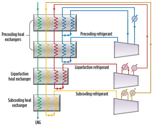
Operation of gas compression station SC3. The gas flow in the pipeline can be accomplished—without significant pressure losses—to maintain the gas flow to operating values in the GG1 pipeline at Hassi R’Mel to Bejaia, Algeria. A gas compression station, commissioned in December 2008, is installed to compensate pressure drops along the pipeline. The SC3 gas compression station, located in Djelfa, is equipped with main and auxiliary equipment: three gas turbines, a generator turbine and a control building equipped with a digital control system (DCS).
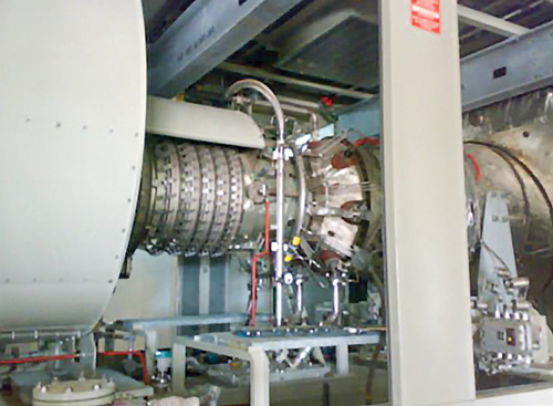
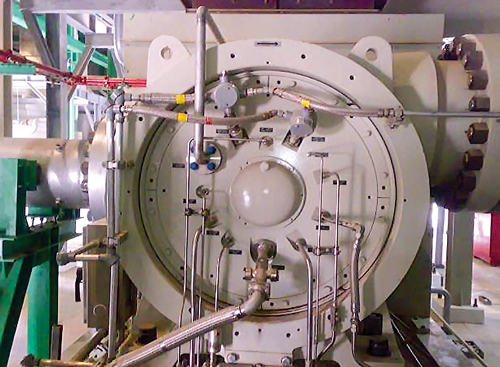
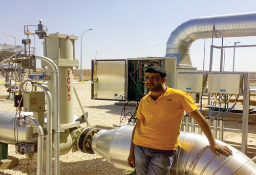
The three gas turbines have a maximum power of 15.3 MW, a thermal rise to 36.2% and a maximum speed of 11,220 rpm, coupled to a centrifugal-type compressor. The compressor has a maximum speed of 8,856 rpm, a minimum suction pressure of 35 bar and a maximum pressure and repression of 72 bar, as shown in Figs. 1, 2 and 3. The role of this station is to increase the gas transport capacity of the pipeline from 7 Bm3y to 13 Bm3y, an increase of approximately 85%.
|
Fig. 1. Gas turbine at Djelfa compression station. |
 |
|
Fig. 2. Centrifugal gas compressor at Djelfa. |
 |
|
Fig. 3. Installation at Djelfa gas compression station. |
 |
The gas turbine combines high-performance operation with rugged industrial construction. This design philosophy allows for high efficiency, low maintenance and a long service life. The turbine is also designed for a high degree of compliance. A centrifugal gas compressor for both gas pipeline applications was also installed in the SC3 station.
During the typical combustion process (Fig. 4), air is drawn into the gas turbine air inlet and is compressed by the multistage, axial-flow engine compressor. The compressed air is directed into the annular combustion chamber at a steady flow. Fuel is injected and mixed with the compressed air, and ignited during the start cycle. Continuous combustion will be maintained as long as the flows of pressurized air and fuel are adequate. Hot pressurized gas from the combustor expands through and drives the turbine, dropping in pressure and temperature as it exits the turbine. This combustion cycle converts the energy in the fuel into kinetic rotating power at the turbine output shaft.10
|
Fig. 4. The combustion process. |
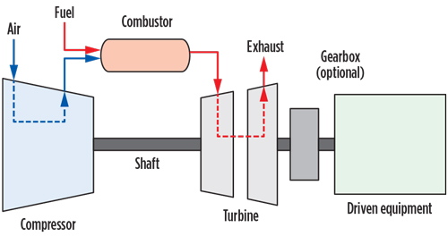 |
For combustion, the gas turbine requires approximately one-fourth of the total air it compresses. The excess air is mixed with the combustion products to reduce the gas temperature at the turbine’s first-stage inlet. The cooling air also keeps metal temperatures in the combustor and turbine assembly relatively low to ensure a long service life.
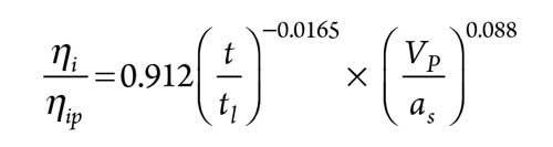
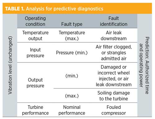
Compressor fouling may be detected by measuring the pressure of the combustion chamber, taking into account the atmospheric temperature it influences, or by measuring the static negative pressure at the compressor inlet. The compressor fouling results in a rapid fall of isentropic efficiency of the compressor, which helps stabilize performance. The isentropic efficiency of the compressor can be calculated as shown in Eq. 1:
 |
where:
ηi = Isentropic efficiency of the compressor at time t (hr)
ηip = Isentropic efficiency of the compressor at time t = 0
tL = Washing time, from which the isentropic efficiency
of the compressor does not vary
VP × (m ÷ s) = Peripheral speed of the compressor wheel
as = Speed of sound in the gas.
In the same circumstances, depending on the flow coefficient, Eq. 2 can be used to calculate the isentropic efficiency of the compressor, as shown in Eq. 2:
 |
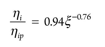
The isentropic efficiency of the compressor is given in Eq. 3:
 |
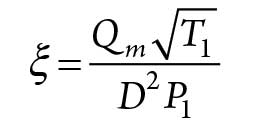
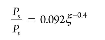
The pressure ratio between the outlet and the inlet of the compressor is expressed as shown in Eq. 4:
 |
where:
Qm = Mass flowrate through the machine
D = Maximum diameter of the wheel
Pe and Te = Pressure and inlet temperature of the machine.
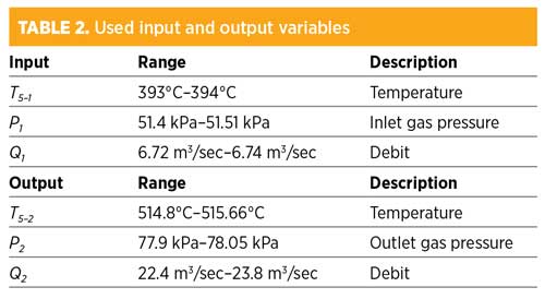
The predictive diagnostics of the compressor require taking into account the analysis of all of the measurements during the exploitation of the machine. Table 1 and Table 2 summarize this analysis.
 |
 |
Adaptive neuro-fuzzy inference system. The proposed adaptive neuro-fuzzy inference system (ANFIS) network architecture and its hybrid learning rule are inspired by a fuzzy inference procedure on a feed-forward network structure (Fig. 5). This ANFIS architecture can be used to model nonlinear functions, to identify nonlinear components online in a control system and to predict a chaotic time series. It is a hybrid neuro-fuzzy technique that brings the learning capabilities of neural networks to the fuzzy inference system.1,11,12,13,14 The learning algorithm tunes the membership functions of the fuzzy inference system using the training of the collected input-output data.
|
Fig. 5. ANFIS structure for TS system with two inputs and one output. |
 |
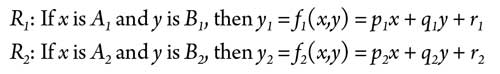
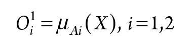
The proposed ANFIS consists of five layers. The adaptive nodes of the neural network are the nodes in Layers 1 and 4. The depicted model defines a controller with two inputs and one output; each input has two membership functions.15,16,17,18,19,20 The rule base is assumed to contain two fuzzy rules of type “if-then,” given by the rules in Eq. 5:
 |
The output of the nodes in Layer 1 is the membership values of the premise part, as shown in Eq. 6:
 |
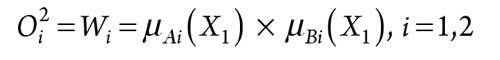
Every node in Layer 2 is a fixed node labeled M, which multiplies the incoming signals, as shown in Eq. 7:
 |
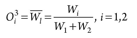
Every node in Layer 3 is a fixed node labeled N for normalization. It calculates the ration of the ith rule’s firing strength to the sum of all rules’ firing strengths, as seen in Eq. 8:
 |
In Layer 4, every node is an adaptive node, while the node function is as shown in Eq. 9:
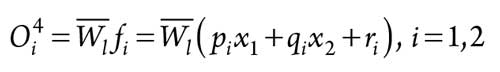 |
where:
= Output of Layer 3
pi, qi and ri = Parameters for the first-order rule.
The overall output of the network can be defined as shown in Eq. 10:
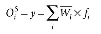 |
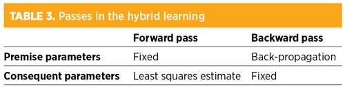
Using the collected input-output data, a fuzzy inference system can be constructed where the membership function parameters are tuned (adjusted) using either a back-propagation algorithm alone, or in combination with a least-squares method. This adjustment allows the fuzzy systems to learn from the data they are modeling. The learning task is done in two passes, using a hybrid learning algorithm, as shown in Table 3. In the forward pass, the first set is fixed, and S2 is optimized by the least squares estimate (LSE). In the backward pass, S1 is tuned by the back-propagation algorithm.
 |
Application results. In this work, the hybrid approaches based on the ANFIS models were used for modeling of the fault diagnosis tasks in the examined gas turbine. The positioned and the control turbines are modeled with three hybrid models: ANFIS1, ANFIS2 and ANFIS3. Each model has five inputs and one output, as presented in Eqs. 11, 12 and 13:
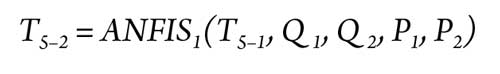 |
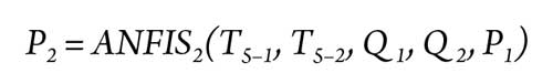 |
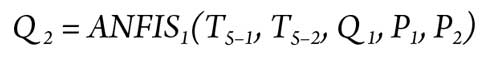 |
The training model task is used to adjust the fuzzy model parameters (premise part and conclusion part) by using the training data. This database contains five vectors of the input variables and their appropriate actions (T5–2, P2 and Q2). The training and testing data sets for elaborating on the models are generated by simulation using the gas turbine model. The training data set contains approximately 348 samples extracted from measured data without faults.
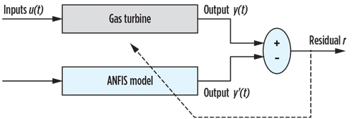
The principle of model-based residue generation is to compare the system behavior with the behavior of the model shown in Fig. 6.
|
Fig. 6. Fault-detection-based models. |
 |
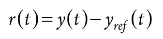
The residue is then calculated as the difference (possibly filtered) between actual output and the outputs estimated using the flowing calculation shown in Eq. 14:
 |
where:
r = Fault indicator (r ≠ 0 → failure and r = 0 → no failure).
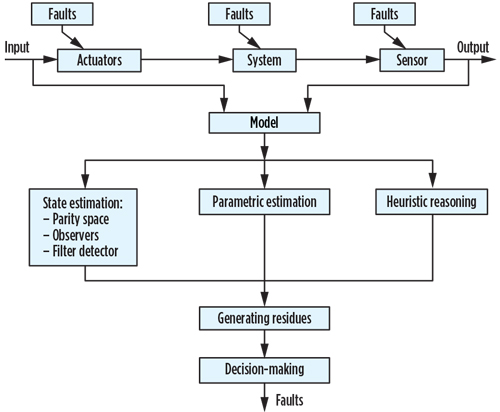
The residue generation is carried to compare measurements from the examined gas turbine with the estimates derived from the model. To generate the residues that will be used in the diagnostic system proposed for the examined gas turbine (Fig. 7), it is necessary to calculate the difference between the output of the industrial gas turbine and the model output designed (rQ, rP and rT).
|
Fig. 7. Diagram of model-based system. |
 |
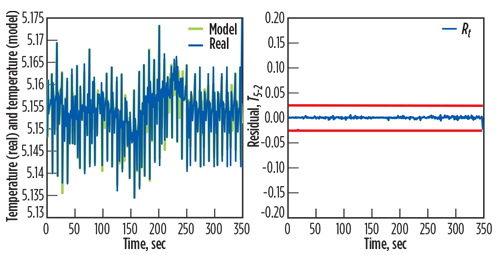
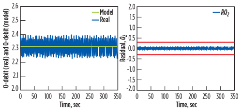
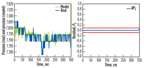
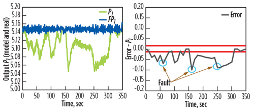
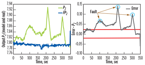
The residuals are the basic factors for fault detection during the monitoring of the gas turbine. The test validations are shown in Figs. 8, 9 and 10. These figures compare the results obtained between the output of the gas turbine model and the measured data of the real output. They also show calculated errors for the two responses.
|
Fig. 8. Actual output of T2 with the estimated T2’, with the associate residual rT(t). |
 |
|
Fig. 9. Actual output of Q2 with the estimated Q2’, with the associate residual rQ(t). |
 |
|
Fig. 10. Actual output P2 with the estimated P2’, with the associate residual rP(t). |
 |
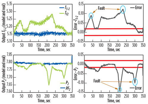
Other tests showed faults based on the measurements of the system and the model. Fig. 11 shows the generated residuals of the two outputs (temperature and outlet gas pressure), for Fault F1 (air leak downstream). This fault is detected within time interval (0 sec, 320 sec). Fig. 12 presents the generated residuals of one output (minimum inlet gas pressure) for Fault F2 (air filter clogged, or strangling admitted air). This fault is detected within time interval (0 sec, 348 sec). Fig. 13 shows the generated residuals of one output (maximum outlet gas pressure) for each fault.
|
Fig. 11. Residuals of two outputs (temperature and outlet gas pressure). |
 |
|
Fig. 12. Residuals of one output (minimum inlet gas pressure). |
 |
|
Fig. 13. Residuals of one output (maximum outlet gas pressure). |
 |
Takeaway. The major interest of this industrial maintenance research is to increase the safety of instruments and to ensure continuity of production. Conventional approaches raise problems with modeling and diagnosis efficiency. The artificial intelligence approach may bring promising solutions for prevention and monitoring.
In this work, the authors developed a fault diagnosis system for a gas turbine installed in a gas compression station using neuro-fuzzy ANFIS techniques. The obtained results show the effectiveness of this approach. GP
Literature cited
- Azar, A. T., “Adaptive network based on fuzzy inference system for equilibrated urea concentration prediction,” Computer Methods and Programs in Biomedicine, Vol. 111, No. 3, September 2013.
- Hafaifa, A., A. Z. Djeddi and A. Daoudi, “Fault detection and isolation in industrial control valve based on artificial neural networks diagnosis,” Journal of Control Engineering and Applied Informatics, Vol. 15, No. 3, 2013.
- Hafaifa, A., A. Daoudi and K. Laroussi, “Application of fuzzy diagnosis in fault detection and isolation to the compression system protection,” Control and Intelligent Systems, Vol. 39, No. 3, July 2011.
- Complete literature cited available online at GasProcessingNews.com.
- Hafaifa, A., G. Mouloud, and B. Rachid, “Fuzzy modeling and control of centrifugal compressor used in gas pipelines systems,” Applied Condition Monitoring: Multiphysics Modelling and Simulation for Systems Design and Monitoring, Vol. 2, 2015.
- Hafaifa, A., M. Guemana and A. Daoudi, “Vibration supervision in gas turbine based on parity space approach to increasing efficiency,” Journal of Vibration and Control, Vol. 21, June 2015.
- Halimi, D., A. Hafaifa, E. Bouali and M. Guemana, “Use modeling as part of a compressor maintenance program,” Gas Processing, September/October 2014.
- Guemana, M., S. Aissani and A. Hafaifa, “Use a new calibration method for gas pipelines: An advanced method improves calibrating orifice flowmeters while reducing maintenance costs,” Hydrocarbon Processing, Vol. 90, No. 8, August 2011.
- Hadroug, N., A. Hafaifa and A. Daoudi, “Valve actuator fault classification based on fuzzy system using the DAMADICS model,” Proceedings of 1st International Conference on Applied Automation and Industrial Diagnostics (ICAAID 2015), Djelfa, Algeria, March 29–30, 2015.
- Mohamed, B. R., A. Hafaifa and G. Mouloud, “Vibration modeling improves pipeline performance, costs,” Oil & Gas Journal, March 2015.
- Bosque, G., I. del Campo and J. Echanobe, “Fuzzy systems, neural networks and neuro-fuzzy systems: A vision on their hardware implementation and platforms over two decades,” Engineering Applications of Artificial Intelligence, Vol. 32, June 2014.
- Fuh, C.-F., R. Jea and J.-S. Su, “Fuzzy system reliability analysis based on level (λ, 1) interval-valued fuzzy numbers,” Information Sciences, Vol. 272, July 10, 2014.
- Konstandinidou, M., Z. Nivolianitou, C. Kiranoudis and N. Markatos, “A fuzzy modeling application of CREAM methodology for human reliability analysis,” Reliability Engineering & System Safety, Vol. 91, No. 6, June 2006.
- Zio, E., P. Baraldi, M. Librizzi, L. Podofillini and V. N. Dang, “A fuzzy set-based approach for modeling dependence among human errors,” Fuzzy Sets and Systems, Vol. 160, No. 13, July 1, 2009.
- Fragiadakis, N. G., V. D. Tsoukalas and V. J. Papazoglou, “An adaptive neuro-fuzzy inference system (ANFIS) model for assessing occupational risk in the shipbuilding industry,” Safety Science, Vol. 63, March 2014.
- Hurtado, J. E., D. A. Alvarez and J. Ramírez, “Fuzzy structural analysis based on fundamental reliability concepts,” Computers & Structures, Vols. 112–113, December 2012.
- Lakhmissi, C., H. Nadji and B. Mohamed, “Hybrid approach based on ANFIS models for intelligent fault diagnosis in industrial actuator,” Journal of Electrical and Control Engineering, Vol. 3, No. 4, 2013.
- Yubin, L., Q. Zhong and W. Guangyuan, “Fuzzy random reliability of structures based on fuzzy random variables,” Fuzzy Sets and Systems, Vol. 86, No. 3, March 16, 1997.
- Golob, M. and B. Tovornik, “Input–output modelling with decomposed neuro-fuzzy ARX model,” Neurocomputing, Vol. 71, Nos. 4–6, January 2008.
- Dong, M. and N. Wang, “Adaptive network-based fuzzy inference system with leave-one-out cross-validation approach for prediction of surface roughness,” Applied Mathematical Modelling, Vol. 35, No. 3, March 2011.
 |
Naji Hadroug is a member of the Applied Automation and Industrial Diagnostics Laboratory at the University of Djelfa in Algeria. He graduated from the University of Djelfa with an MS degree in industrial maintenance. Before pursuing his PhD in industrial automation, he worked on fault control for gas turbines using neuro-fuzzy systems. Dr. Hadroug’s work focuses
on the development of new methods and tools in control fault tolerance for industrial systems. He is also an author and coauthor of several publications and conference papers.
 |
Ahmed Hafaifa is a Full Professor in industrial process (automation/diagnosis) and reliability engineering at the Science and Technology Department of the University of Djelfa in Algeria. He teaches courses on advanced reliability engineering, diagnosis for engineering applications, and fuzzy control and reliability in industrial plants. He is conducting research work in applied automation at the Industrial Diagnostic Laboratory at the University of Djelfa, where he is also Director. His research interests include modeling and control in industrial systems, reliability engineering, fault detection and isolation in industrial processes, and intelligent systems based on fuzzy logic and neural networks. He has supervised several master’s-degree and PhD students, and written a number of papers for archived journals.
 |
Mouloud Guemana is an Associate Professor at the University of Médéa in Boumerdès, Algeria, where he has worked since July 2004. He holds an engineering degree and a PhD in industrial maintenance from the University of Boumerdès. He is an author and coauthor of many scientific papers and research projects. His research interests include industrial maintenance, reliability systems, dynamic systems, diagnostics and reliability optimization.


Comments