
Super-compact BOG recondensing system minimizes equipment lifecycle costs
K. Hayashi, K. Yarimizu and S. Furutani, JFE Engineering Corp., Tokyo, Japan
Processing boiloff gas (BOG) is a challenge for the hydrocarbon processing industry. The industry has been addressing the issue by installing BOG recondensing systems, which reduce power consumption by the BOG compressor.1 To further minimize the lifecycle cost of BOG processing equipment, the authors propose a considerable reduction in the size of the BOG recondenser.
Here, an innovative BOG recondenser with a volume of only 2% of conventional ones is introduced. Patents were filed for the recondenser. The unit’s recondensing performance and benefits, as well as the control system that ensures the safe and stable operation of the entire system, are also described.
Since it began importing LNG from Alaska in 1969, Japan has become the world’s biggest importer and consumer of LNG. Japan also has the largest number of LNG importing terminals in the world, along with rich experience in the design, construction and operation of these terminals.
During this period of nearly 50 years, the country has confronted various technical issues regarding LNG, and it has demonstrated the methods of overcoming these problems to the industry. The technology introduced here is one of the products based on this experience.
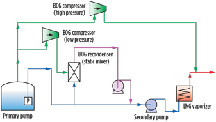
Conventional BOG processing: Power consumption. The tanks, piping and equipment that contain LNG are always subject to heat input because the temperature of the liquefied gas, at approximately –160°C, is far below ambient temperature. LNG is circulated through the piping and equipment to remove the input heat and maintain the equipment at cryogenic temperature. As a result, the heat is gathered to the LNG tank, and the LNG in the tank is partly evaporated by the collected heat and the direct heat input at the tank. This evaporated gas is the BOG (Fig. 1).
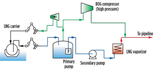 |
| Fig. 1. Process flow of LNG import terminal without BOG recondensing system. |
Due to its evaporation in the tank, the BOG is discharged to the connected pipeline to keep the tank under the design pressure. The BOG compressor pressurizes and sends the BOG out to the pipeline. However, the compressor requires huge power, as the pipeline operating pressure is generally very high (5 MPa or more). This increases the OPEX of the terminal.
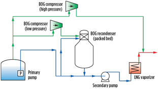
Conventional BOG recondensing system. A BOG recondensing system, which liquefies BOG by utilizing the cold energy of LNG, will greatly reduce the power consumption of the compressor, as pumping the BOG in the liquid phase requires considerably less power than compressing the same in the gas phase.
Several types of BOG recondensing systems have been commercialized. The packed-bed type (Fig. 2) is most widely applied. However, it requires a large and heavy recondenser, which consists of two portions with a skirt. The upper portion is the packed-bed section where the BOG is liquefied as it contacts with the subcooled LNG. The lower portion is the holdup section, which serves as a suction drum for the secondary pump. The skirt is required to provide the net positive suction head (NPSH) for the secondary pump.
 |
|
Fig. 2. Process flow of packed-bed BOG recondensing system. |
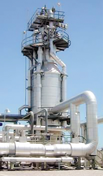
Due to its design, this type of recondenser is very high, as shown in Fig. 3. This height requires operators to climb up platforms for regular inspections and maintenance, which increases their workload and risk. It also requires a large crane whenever the operators need to replace the packing.
 |
|
Fig. 3. Packed-bed BOG recondenser. |
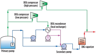
Another type of recondenser is the heat exchanger type (Fig. 4), which is more common in Japan. LNG flows into the shell, the BOG flows into the tubes, and the gas is condensed by subcooled LNG. This type of recondenser is also large because it needs a wide heat transfer area. The large shell and the dense-allocated tubes inside add to its weight.
 |
|
Fig. 4. Process flow of heat exchanger BOG recondensing |
As shown in Fig. 4, this type of recondenser requires two additional pumps in the system. One is for pumping LNG to the heat exchanger, and the other is for discharging the liquefied BOG to the secondary pump. This configuration will increase OPEX.
Inspection and maintenance are also challenging with this type of configuration. The operator must discharge all LNG in the shell to detach the tube bundle for inspection. Although LNG and BOG are clean and noncorrosive, authorities require scheduled inspections in some places, such as Japan.
New BOG recondensing system: Process description. This recondenser is a vertical pipe structure (Fig. 5). LNG flows into the recondenser, and BOG is introduced into the LNG through proprietary nozzles inside. The nozzles convert the BOG into very fine bubbles, and the bubbles are recondensed immediately.
 |
|
Fig. 5. Process flow of new BOG recondensing system. |
The nozzles were developed through trial-and-error laboratory tests with water and steam. Significant experiments were carried out to find the optimum arrangement of the nozzles and other parameters.
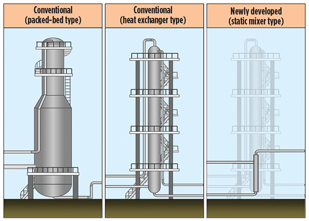
The dominant advantage of the new recondenser is its compactness. As shown in Fig. 6, the recondenser is smaller in size and weight than the conventional types. In a typical case (BOG recondensing capacity = 14 tph), the diameter is only 0.3 m and the length is 3 m. A heat exchanger-type BOG recondenser with the same capacity is 1 m in diameter and 12 m in height. This means that the new recondenser is only 2% of the volume of the conventional recondenser, and is approximately 1/15 the weight.
 |
|
Fig. 6. Conventional recondenser designs vs. new |
The significant compactness of the new recondenser design brings benefits in the construction and operation of the recondensing system. In the aforementioned typical case, CAPEX is reduced by approximately 20%, and the footprint is decreased by approximately 40%. OPEX is expected to be 60% lower than that of the heat exchanger-type recondenser because fewer pumps are required.
The new recondenser system is also less labor-intensive in many ways. It is virtually maintenance-free because of its simple internal structure. The control system is straightforward and does not require manual operation.
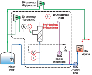
System configuration and control. The configuration of the system is shown in Fig. 7. The low-pressure BOG compressor sends the BOG to the recondenser, and the recondenser mixes the BOG with LNG to liquefy it. The BOG/LNG mixture pump sends the mixture to the secondary pump.
 |
|
Fig. 7. System configuration of new BOG recondensing system. |
The system control is quite simple. The LNG flowrate to the BOG recondenser is maintained at the set value by controlling the outlet flowrate of the BOG/LNG mixture pump. The set value is not affected by the BOG flowrate and is unchanged in principle. The value is reduced only when the LNG regasification rate becomes lower than the initial set value.
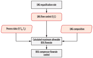
The maximum allowable BOG flowrate (i.e., the amount of BOG that can be recondensed) is calculated from the process data shown in Fig. 8. The flowrate of the low-pressure BOG compressor is always kept at or below the calculated allowable value. If the BOG generated is greater than the allowable value, the excess BOG is sent to the pipeline by the high-pressure BOG compressor.
 |
|
Fig. 8. Basic control philosophy of new BOG recondensing system. |
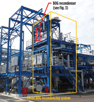
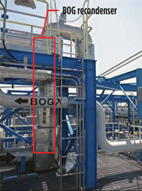
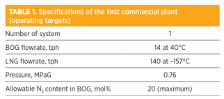
First commercial plant. The first commercial plant (Figs. 9 and 10) was installed in the Chita-Midorihama works of Toho Gas Co. Ltd. Its specifications are shown in Table 1. The commissioning of the plant was completed in June 2016, and its performance was confirmed to be in accordance with the design. Details of the test results are provided in the
following sections.
 |
|
Fig. 9. Overview of new BOG recondensing system. |
 |
|
Fig. 10. The new BOG recondenser. |
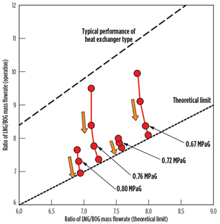
BOG recondensing performance. The actual BOG recondensing performance, represented by the ratio of LNG/BOG mass flowrate, is far better than the typical heat exchanger-type recondenser and close to the theoretical limit (Fig. 11). The theoretical limit is the minimum LNG/BOG ratio where all BOG can be recondensed completely, assuming 100% heat exchanger efficiency. The dots connected by the red lines in Fig. 11 indicate the state in which the operating LNG/BOG ratio is gradually reduced toward the theoretical limit while maintaining other conditions, such as pressure, temperature, etc. The series of dots demonstrate that the new recondenser, as a device, has the potential to perform at conditions very close to the theoretical limit.
 |
|
Fig. 11. BOG recondensing performance of the first |
Another beauty of the recondenser is the very small pressure loss. If the pressure loss is large, the pressure at the outlet of the recondenser will be reduced, and the LNG sensible heat for the recondensation will also be reduced. Therefore, the BOG recondensing capacity will be diminished.
Safe operation. The behavior of the entire recondensing system was tested in case the operating conditions deviated suddenly. When the BOG flowrate or the LNG pressure changed suddenly, the system maintained safe and stable operations.
The emergency shutdown sequence was also tested. The system is designed to initiate an emergency shutdown when the BOG is not completely recondensed and discharged downstream of the recondenser. The test conditions were created by manually reducing the LNG flowrate. The behavior of the system conformed to design specifications, and the system made an emergency shutdown in a safe manner.
Noise and vibration have been negligible throughout the commissioning and initial commercial operation. The continued absence of noise and vibration problems will minimize any potential issues related to these elements throughout the recondenser’s long lifecycle.
Takeaway. The BOG recondensing system that has been developed is much smaller and lighter than conventional recondensing systems. This advantage contributed to the reduction of lifecycle cost and footprint for the recondenser. Additionally, its maintenance-free structure and simple control philosophy will minimize the workload of the operators.
The first commercial plant has demonstrated excellent BOG recondensing performance that is close to the theoretical limit. The plant has also demonstrated continuous, safe and stable operation, even during a sudden fluctuation in operating conditions. Noise and vibration were measured at negligible levels. GP
ACKNOWLEDGMENTS
The authors express their gratitude to the codeveloper, Toho Gas Co. Ltd., which cooperated and contributed greatly to the design, construction and commissioning of the first commercial plant.
LITERATURE CITED
1Lemmers, S. P. B., “Simplify BOG recondenser design and operation—Part 1,” Gas Processing, June 2014; and Lemmers, S. P. B., “Simplify BOG recondenser design and operation—Part 2,” Gas Processing, August 2014.
 |
Kanetoshi Hayashi is group manager of the research center of engineering innovation for JFE Engineering Corp. He joined JFE in 1990 and has been responsible for the research and development (R&D) of processes and equipment in the energy and environmental areas since that time. His areas of expertise include heat transfer, mass transfer and fluid dynamics.
His R&D project involvement has included thermal energy storage, energy conversion and multi-phase/phase-change processes. He was a visiting researcher for Argonne National Laboratory in the US between 1997 and 1999. He earned his MS degree in mechanical engineering from the University of Tokyo, Japan in 1990.
 |
Keiji Yarimizu is a project engineer in the energy division of JFE Engineering Corp. and is responsible for project management of LNG import terminals. He has 20 years of experience in the design of underground LNG storage tanks and in the process engineering and commissioning of LNG import terminals. He has been involved in various LNG import terminal projects for power and city gas companies in Japan. Mr. Yarimizu earned his MS degree in mechanical engineering from Tokyo Metropolitan University, Japan in 1995, and joined JFE in the same year.
 |
Shigeya Furutani is a senior engineer in the energy division of JFE Engineering Corp., responsible for business development in the oil and gas midstream area, including the LNG value chain. He joined JFE in 1994 and has over 20 years of experience in engineering, construction and project management of onshore and offshore pipeline projects in Japan, Vietnam, Saudi Arabia and Hong Kong. He earned his MS degree in civil engineering from Kobe University, Japan in 1994, and is a registered professional engineer in Oregon, US.


Comments