
Design an alternate purge system for an LNG plant fired heater
S. Ahamad and R. Vallavanatt, Bechtel Corp., Houston, Texas
LNG trade is expanding globally at a rapid pace. Natural gas is brought to market either with a traditional pipeline or through an LNG supply chain. Gas is the cleanest-burning hydrocarbon fuel, producing lower levels of greenhouse gas emissions than either oil or coal. The economics of an LNG plant are driven by the capacity of the plant, the price of LNG sold, the cost of feed gas, the installed cost and the operational costs of the facility.
The total installed cost of fired heaters is also increasing quickly. The fired heater purge system proposed here can be installed for a fraction of the cost of widely available purge systems, while helping reduce heater installed cost. The proposed design also improves the operation of the plant by providing an efficient and cost-effective purge system.
Heater purge cycles. Prior to each fired heater startup, combustible gases that may have entered the fired heater during the shutdown period are purged from the firebox. A timed pre-ignition purge cycle should be repeated at every startup of the fired heater.
The default purge time period is typically 15 min for the volume of the target three-heater combustion chamber (radiant section) to change. In a typical refinery setup, where steam is readily available, low-pressure steam is injected into the radiant section for at least 15 min. Steam purging can be a problem in cold-weather locations due to steam condensing.
Traditionally, steam has been used in refineries and petrochemical plants for the purging of natural-draft-fired heaters. Unlike refineries and petrochemical plants, LNG plants are usually designed without a steam system. Instead, hot oil is used to meet the heating requirement of the plant.
Waste-heat-recovery units are also used at the turbine exhaust point to heat the hot oil and other process streams. A fired heater is generally used in lieu of waste heat recovery and as a startup and a backup. In LNG plants, where steam is generally not available, an air blower—an expensive alternative—can be used to introduce air to the radiant section for purging.
An inexpensive and safe way to purge a natural-draft heater using plant air in lieu of steam or an air blower is described here.
Type of fired heaters. Fired heaters can be categorized into four types based on type of draft:
- A natural-draft heater, the most commonly used type, uses a stack effect to induce the combustion air and remove flue gases.
- An induced-draft heater uses a fan to remove flue gases and maintain a negative pressure to induce combustion air. This type of draft system is used when the height of the stack is inadequate to meet the draft requirements of the heater.
- A forced-draft heater uses a combustion air fan to supply combustion air. A stack is still required to create a negative draft inside the furnace.
- A balanced-draft heater uses a forced-draft fan to supply combustion air and an induced-draft fan to remove flue gases. A balanced-draft system is used mostly with an air preheating system.
Purge requirements. A purge ensures that the concentration of any combustible hydrocarbon mixture present in a fired heater is reduced to a safe level before ignition by a purging medium.
Per API Standard 560, “Fired heaters for general refinery services,” the purge should continue for a minimum of three firebox volume changes within 15 minutes to consider the combustion cavity free of hydrocarbons. In forced-draft or balanced-draft heaters, the forced-draft fan can be used to purge the firebox in lieu of purge steam.
In the past, the practice was to purge the natural-draft-fired heater by allowing ambient air to pass through the system. The stack damper and the burner air register should be kept open for a period of 20–30 minutes for ambient air to pass through the heater and remove the combustibles. However, there is no proven method to establish that the time period provided for the purge is sufficient.
The purge air flowrate through the heater depends on ambient conditions at the site. Also, this method will not ensure the requirement of three volume changes in 15 minutes.
Purge using a fan. As mentioned previously, a fan can be used to purge a natural-draft-fired heater. This system requires the installation of a fan, as well as ducting from the fan to the floor of the heater.
The fan supplies the air through ducting to the heater for purging. However, the installation cost for this system is significantly higher than for the proposed eductor design. The typical equipment cost for a purge air system (fan and associated ducting) and the related control mechanisms can cost $350,000 or higher. The total installed cost could be close to $1 MM.
The cost of the purge fan system then becomes a significant factor in the overall heater installed cost. Furthermore, adding a piece of rotating equipment results in added maintenance and related costs.
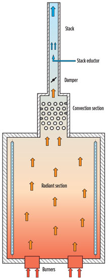
A new purge system for fired heaters. In any refinery, and especially in an LNG plant, the plant air is always available. This air is used in eductors as a motive force to purge the fired heater. The eductor is installed in the bottom section of the stack, preferably below the damper. The burner dampers and the stack damper must be fully open during fired heater purging.
As part of the burner lightup, when the required prelight tasks are completed, the burner management system allows the purge cycle to begin. Thereafter, the purge signal is activated and the plant air is introduced to the eductor. The plant air exits the eductor at sonic velocity, creating negative pressure (i.e., draft) below the eductor. In turn, the created draft pulls the air through burners and purges the firebox. The eductor should be designed to create sufficient draft as required for the purge air flowrate.
Basic design requirements of stack eductor. Following are some of the basic design features of an eductor purging system:
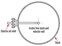
- Locate the eductor as close as possible to the base of the stack, and exactly in the center
- Ensure that the location of the eductor does not interfere with the operation of the stack damper; the damper should be able to fully open or close without interfering with eductor piping
- All piping and plugs exposed to flue gas should be made of stainless steel as a minimum; the material should be suitable for the maximum expected flue gas conditions
- Match the mark flange connection at the stack to ensure that the eductor discharge is pointed upward.
A typical design sketch of an eductor for a fired heater is shown in Figs. 1 and 2.
 |
|
Fig. 1. Fired heater with stack eductor |
 |
|
Fig. 2. Diagram of a typical stack eductor. |
Eductor design calculation. Following is a step-by-step calculation to design a stack eductor purge system for a fired heater:
- Calculation of purge air flowrate. As required by API 560, the purge system should be designed for a flowrate that provides a minimum of three firebox volume (vol) changes within 15 min. Local standards, which may require higher flowrates, should also be checked.
The required purge air flowrate is shown in Eq. 1: (1)
(1)
where:
Fa=Required purge air flowrate, ft3/hr
Vr=Radiant section (firebox) vol (purge vol), ft3
t=Purge time for one vol change, min. - Draft calculation for purge air flow. Once the required purge air quantity is known, the next step is to calculate the draft required to pull the purge air through the burner, the firebox, the convection section and the stack, as shown in Eq. 2:
Draft = ∆PB + ∆PCS (2)
where:
Draft=Draft required to pull purge air through the fired heater, in. water column (inWC)
∆PB=Pressure drop across burners, inWC
∆PCS=Pressure drop across convection section, inWC.
The purge air will experience pressure drop, mostly across the burner and the convection section. Pressure drop in other sections is negligible and can be ignored.
Pressure drop across the burners and the convection section should be calculated at the required purge air flowrate, Fa. These values are estimated based on heater design data.
Design flue gas pressure drop is available for the convection section at the design flue gas flowrate. Burner design air pressure drop is available at the design air flowrate. Values for ∆PB and ∆PCS can be calculated based on these design data. - Calculation of eductor throat diameter and air flowrate. The critical pressure, critical density and sonic velocity at the eductor throat (nozzle) can be calculated with Eqs. 3–7:
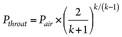 (3)
(3)
where k = 1.4 for air, use Eqs. 4–7:
Pthroat = 0.528 Pair (4)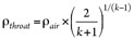 (5)
(5)
ρthroat = 0.634 ρair (6)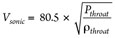 (7)
(7)
where:
Vsonic=Sonic velocity at throat, ft/s
k=Specific heat ratio (1.4 for air)
Pair=Air supply pressure to eductor, psia
Pthroat=Air pressure at eductor throat, psia
ρair=Air density at eductor supply pressure, lb/ft3
ρthroat=Air density at eductor throat, lb/ft3.
The area of eductor throat discharge is calculated using Eq. 8: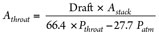 (8)
(8)
where:
Draft=Draft required to pull purge air through fired heater, inWC
Astack=Stack cross-section area, in.2
Athroat=Throat area, in.2
Patm=Atmospheric pressure, psia.
Multiply the area of throat by a factor of 1.2, allowing for inefficiencies, as shown in Eq. 9: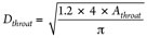 (9)
(9)
The flowrate of plant air through the eductor throat is calculated using Eq. 10:
Fpa = 25 × 1.2 × ρthroat × Athroat × Vsonic (10)
where:
Dthroat=Diameter of throat, in.
Fpa=Plant air flowrate through eductor throat, lb/hr.
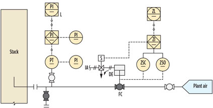
Overall requirements. Following control and instrumentation (Fig. 3), it is recommended to ensure the operation of the eductor by using several checklist points:
- For purge air flow verification, it is recommended to provide a pressure indicator (PI) downstream of the isolation valve. When the isolation valve is open, this PI will indicate a pressure very close to the supply pressure. This PI does not indicate any pressure if there is no flow through the line. Under a no-flow case, the isolation valve can be closed, causing no flow and fixing the problem.
- The stack damper is required to be fully open during purging. For a manually operated damper, the open position can be ensured by checking the damper positioner. For automatic dampers or dampers that can relay the position to a safety system, the damper open position can be interlocked as a permissive to start the purge. It can be interlocked to prevent the pre-purge period proceeding, unless the damper is in the correct position and remains there for the full purge period.
- Burner air registers must be fully open during purging. The open position of the air register can also be automated, and can be added as a pre-purge permissive. A positioner can be added to each of the air registers, which will relay the open position to the safety system.
- Eductor air flow failure at any time during the purge operation will initiate a safety shutdown of the purge cycle, and a new purge cycle must be started.
A typical instrumentation requirement on a plant air supply line for an eductor is shown in Fig. 3.
 |
|
Fig. 3. Instrumentation for eductor. |
Most of the fired heater instruments are relayed to a burner management system (BMS) and/or a distributed control system (DCS), which can be used for the purge permissive. If these conditions meet the permissible limit, then the purge can start. Following is a list of purge permissives for a typical natural-draft-fired heater. These initial starting conditions must be met before the heater purge system can be started:
- Burner upstream and downstream fuel gas block valves are closed; to be verified by close-limit switches
- Burner fuel gas vent block valve is open; to be verified by open-limit switch
- Pilot burner upstream and downstream block valves are closed; to be verified by close-limit switches
- Pilot burner vent block valve is open; to be verified by open-limit switch
- No pilot flames detected; to be verified by ionization rod on pilot flame
- No burner flames detected; to be verified by ultraviolet scanner on main flame
- Stack damper is open completely; to be verified by open-limit switch
- Burner’s air register is open
- No interlock is active.
The purge is initiated after the purge permissives are established. The purge timer will start after several requirements are met:
- Plant air block valve will open; to be verified by open-limit switch
- Plant air pressure is above set pressure; to be verified by pressure transmitter
- A light should turn on, indicating that a purge is in progress; the heater must be purged for the required time, as established by calculation.
During this purge time, no alarms, shutdowns or abnormal conditions are allowed to occur. If this happens, the purge is suspended and must be restarted from the beginning. A purge failure alarm should be provided. The anomaly must be corrected, and the alarm reset must be pressed to clear the purge failure alarm. After the purge is completed, the fired heater is ready for lightup.
Case study parameters. A case study was conducted on the purge of a fired heater with the following parameters:
- Heater dimension:
- Radiant section diameter inside refractory = 17 ft
- Radiant section height = 28 ft
- Radiant section volume = 6,355 ft3
- Calculation of purge air flowrate:
- Time required for 1 vol change = 5 min
- Air flowrate required for purging = 76,265 ft3/hr = 5,498 lb/hr (based on ambient air density of 0.072 lb/ft3 at 90°F)
- At fired-heater design conditions:
- Air flowrate at heater design case = 34,286 lb/hr = 475,580 ft3/hr
- Flue gas rate at heater design case = 36,429 lb/hr = 1,511,993 ft3/hr (air and flue gas flow data is taken from heater design simulation results)
- Average flue gas density in convection section = 0.024 lb/ft3 (at flue gas average temperature of 1,117°F in convection section)
- Draft at hearth level (pressure drop across burner) = 0.36 inWC
- Convection loss = 0.32 inWC
- At purge conditions:
- Pressure drop through burners = 0.0093 inWC
- Convection loss = 0.0008 inWC
- Draft required at heater floor for purge flow = 0.0101 inWC
- Stack diameter = 60 in.
- Stack cross-section area = 2,827 in.2
- Eductor supply air pressure = 87 psia
- Critical pressure of air at nozzle throat = 45.9 psia
- Density of eductor air at supply pressure = 0.45 lb/ft3
- Critical density of air at nozzle throat = 0.285 lb/ft3
- Sonic velocity = 1,023 ft/s
- Area of eductor nozzle discharge = 0.0107 in.2
- Diameter of nozzle = 0.128 in. (3.3 mm)
- Purge air flowrate to the eductor = 94 lb/hr.
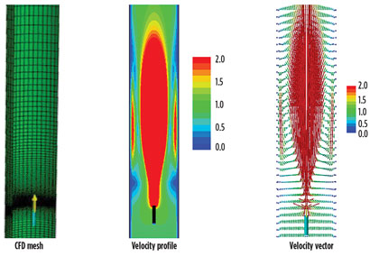
Verification by CFD analysis. A computational fluid dynamics (CFD) analysis was carried out for one of the fired heaters. The result of the CFD analysis was found to be very close to calculation values (Fig. 4).
 |
|
Fig. 4. Snapshot of results from CFD simulation. |
Further operating data was collected to verify the draft created by the eductor. Operating data clearly indicated that the draft created by the eductor matched the calculation results.
Results. Purging the fired heater, prior to each fired heater startup, is a critical safety requirement. Any combustible gases present inside the firebox must be removed prior to ignition.
The innovative design of a fired heater purge system presented herein is simple to implement and provides purge results with full reliability. This design is more cost effective compared to the next available option of using a purge fan.
This air eductor design has been verified by CFD results, and the air eductor has been used and proven on several natural-draft-fired heaters. Implementation of this design makes the fired heater design more cost effective and also improves its operation. GP
 |
Sultan Ahamad is a senior fired heater specialist at Bechtel Corp. in Houston, Texas. He has more than 17 years of experience in the design, engineering and troubleshooting of fired heaters and combustion systems for the refining, petrochemical and LNG industries. He graduated from the Indian Institute of Technology in Roorkee, India, with a degree in chemical engineering. He is a member of the American Petroleum Institute’s subcommittee on heat transfer equipment.
 |
Rimon Vallavanatt is a senior principal engineer at Bechtel Corp. in Houston, Texas. He has more than 40 years of experience in the design, engineering and troubleshooting of fired heaters, thermal oxidizers, boilers and flares. He graduated from the University of Kerala in Trivandrum, India, with a degree in mechanical engineering. He also received a degree in industrial engineering from St. Mary’s University in San Antonio, Texas. Mr. Vallavanatt is a registered professional engineer in the state of Texas and has served on the American Petroleum Institute’s subcommittee on heat transfer equipment for the past 30 years.


Comments