
Retrofit an LPG plant for improved output and ethane recovery
A. K. Shatla, El-Wastani Petroleum Co., Cairo, Egypt;
and A. A. Abdelwaly, Cairo University, Cairo, Egypt
An LPG plant in Damietta, Egypt, operated by El-Wastani Petroleum Co. (WASCO), contains a turboexpander LPG recovery unit. Due to the increased demand for ethane and LPG in Egypt, a retrofit was recommended for the WASCO plant to increase LPG recovery and produce ethane as a new product.
A conceptual design is presented here, along with a preliminary economic study for retrofitting the plant. The retrofit study was based on two proprietary ethane-recovery (ER) processes and was modeled on commercial process simulation software.*
The results of the study showed that the ultra-high ER (UHER) process—a modification of an established ER process—gave a better return on investment and lower payback time, and was more attractive for implementation.
Introduction. Vast reserves of natural gas exist in Egypt, with strong potential for additional discoveries. The western desert regions, the Nile Delta, and the Mediterranean Sea have shown great promise for further increasing Egypt’s gas production in the near future. However, low levels of NGL recovery in domestic gas processing plants force Egyptian petrochemical companies to import their feedstocks at high prices due to high transportation costs. However, domestic gas processing companies could provide a large percentage of those feedstocks if NGL recovery levels are increased.
WASCO owns and operates a network of wells and a gas gathering system in the Nile Delta area. The gas stream is directed to a central processing facility (CPF) located at Damietta. The WASCO CPF was originally designed to process 160 MMscfd of feed gas (with a molecular weight of 19.13) and 4 Mbpd as raw condensate (with a condensate/gas ratio of 25 bbl/MMscf) to produce 245 tpd of LPG product for the local market, 5 Mbpd of stabilized condensate and 153 MMscfd of sales gas for the Egyptian national gas grid. In 2014, plant processing capacity increased to 200 MMscfd of feed gas.
WASCO plant processing facilities are segregated into two stages:
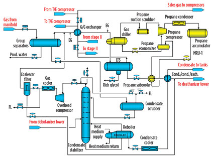
- Stage 1: The process equipment installed in Stage 1 includes group separators, a gas dewpoint reduction facility that uses a mechanical refrigeration unit (MRU), a glycol injection unit, a regeneration unit and a condensate stabilization unit.
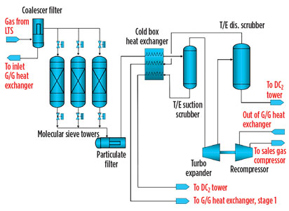
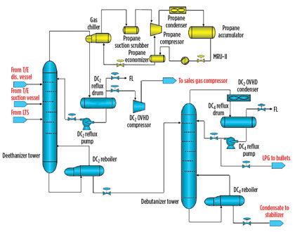
- Stage 2: The process equipment installed in Stage 2 includes a molecular sieve dehydration unit, a turboexpander, deethanizer and debutanizer fractionation towers and LPG storage bullets.
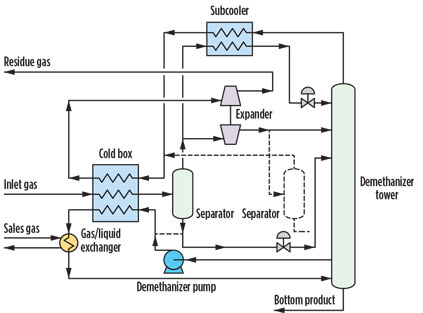
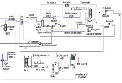
Fig. 1 shows a process flow diagram of Stage 1, while Figs. 2 and 3 show a flow diagram of Stage 2.
 |
|
Fig. 1. Flow diagram of WASCO plant Stage 1. |
 |
|
Fig. 2. Flow diagram of WASCO plant Stage 2 (molecular sieve unit and |
 |
|
Fig. 3. Flow diagram of WASCO plant Stage 2 (fractionation towers). |
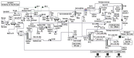
Modeling the existing plant. A model of the plant has been built using commercial software with the following conditions:
- Raw gas flow from wells: 182 MMscfd
- Raw condensate flow from wells: 3.9 Mbpd.
Fig. 4 shows a process flow diagram of the model.
 |
|
Fig. 4. Flow diagram of the existing plant model. |
The model results were compared with actual design and production data, which showed that the model provides good matches with both design and history production data. The retrofitting process was carried out on this static model as the best representation of the actual plant.
Retrofit using ethane recovery. The key changes in the plant retrofit were in the turboexpander unit downstream of the molecular sieve unit, where the main cryogenic process takes place.
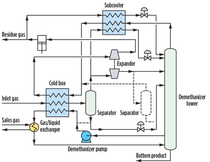
Fig. 5 shows the plant design after being retrofitted to use a proprietary ER process, where new modifications are shown in bold and unused modifications are represented by dotted lines.
 |
|
Fig. 5. Schematic drawing of modifications using the ER process. |
The key changes were:
- A demethanizer tower was added where the methane-free NGL product is recovered as a bottom product
- Gas from the turboexpander suction vessel was split into two streams: one to the turboexpander and the other to a reflux stream for the demethanizer tower
- A new heat exchanger (subcooler) was added to provide a cold reflux stream to the demethanizer tower
- A new demethanizer pump was added to pump NGL through the cold box and the gas/liquid exchanger to provide bottom heat for the demethanizer tower
- A new gas/liquid exchanger was added to transfer heat from hot sales gas to NGL from the demethanizer tower and used as a side reboiler.
The retrofit design was then modeled in a static model using commercial software. Fig. 6 shows a process flow diagram of the model. The model was built according to the following steps:
- Gas from the cold box to the turboexpander suction vessel was maintained at the same temperature as the original case (–40°C)
- Gas from the suction vessel was split into two streams, with a split ratio of:
- Stream 1 to turboexpander: 53% of the gas from the suction vessel
- Stream 2 to subcooler: 47% of the gas from the suction vessel.
 |
|
Fig. 6. Flow diagram of the turboexpander using the ER process. |
This optimum ratio was chosen based on several factors:
- A higher ratio for Stream 1 with the same outlet temperature from the subcooler (Stream 3) would increase ER, but the temperature of the residue gas would also increase, and so it would not be sufficient to cool the gas to the suction scrubber to –40°C (temperature cross in the cold box would occur)
- A lower ratio for Stream 1 would reduce ER, which also means that a higher ratio for Stream 2 would cause the turboexpander power to increase more than the maximum design power, which would require a new turboexpander
- The temperature of Stream 3 from the subcooler was optimized to –61°C to give the highest ER
- A distillation column was added to perform as a demethanizer with 30 trays (the normal number of trays for demethanizer towers is 45–30) and with operating pressure optimized at 300 psig (the normal operating pressure for demethanizer towers is 500 psig–300 psig) to give higher ethane recovery
- To save demethanizer reboiler power, a side stream from the tower is recycled through the cold box, which helps to cool the inlet gas stream, which is then heated to 19°C in the gas/liquid exchanger and partially vaporized before it reenters the tower bottom to provide the heat required for fractionation and reduce methane content in the bottom product.
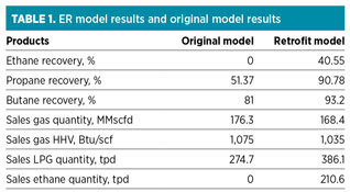
ER retrofit model results. Table 1 shows the ER model results and compares them with the original model before retrofitting, which indicates that:
- The model produced ethane as a new product, and ER increased from 0% to approximately 41%, producing approximately 210 tpd of pure ethane
- Both propane recovery and butane recovery increased, leading to an increase in LPG production of approximately 112 tpd
- Both sales gas quantity and heat of combustion (HHV) decreased due to increasing NGL recovery.
 |
A comparison of plant equipment performance before and after the retrofit showed that the following equipment exceeded the design capacity and needed to be replaced:
- Deethanizer tower
- Deethanizer reflux pumps
- Deethanizer condenser
- Deethanizer reflux drum
- Deethanizer reboiler
- Condensate/condensate exchanger
- Turboexpander suction vessel.
Retrofit using ultra-high ER. The key modification in this retrofit was applied to the turboexpander area, as in the ER model. Fig. 7 shows the plant design after being retrofitted to use a proprietary ultra-high ethane recovery technology. New modifications are shown in bold, and the unused modifications are represented by dotted lines. The key changes were:
- A demethanizer tower was added where the methane-free NGL product is recovered as a bottom product
- Gas from the turboexpander suction vessel was split into two streams: one that goes to the turboexpander and the other that is a reflux stream for the demethanizer tower
- A small portion of residue gas was withdrawn, condensed, subcooled and then flashed in the demethanizer top tray to perform as a reflux
- A new three-pass heat exchanger was added to provide a cold reflux stream to the demethanizer tower
- A new demethanizer pump was added to pump NGL through the cold box and the gas/liquid exchanger to provide bottom heat for the demethanizer tower
- A new gas/liquid exchanger was added to transfer heat from hot sales gas to NGL from the demethanizer tower; this exchanger is used as a side reboiler.
 |
|
Fig. 7. Schematic drawing of modifications using the UHER process. |
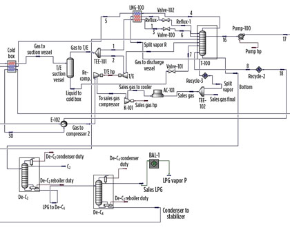
The modifications for the UHER method were the same as those used in the ER method, except for the withdrawn portion of the residue gas that is subcooled and refluxed through the demethanizer tower. The ER retrofit design was modeled in a static model, using commercial software. Fig. 8 shows a flow diagram of the model.
 |
|
Fig. 8. Flow diagram of the UHER model. |
The model was built using the same steps as the ER model, except that a portion of the sales gas (5.7%) is recycled back to the subcooler, where it is cooled to –81°C and then flashed in the demethanizer top tray. The recycled gas ratio and its subcooled temperature are optimized to give the highest ethane recovery.
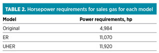
The recycled gas represents an extra load on the sales gas compressor’s hp. However, this extra load is covered with the existing hp of the sales gas compressors in the LPG plant (12,710 hp). Table 2 shows the horsepower requirements for each model.
 |
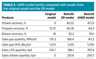
UHER retrofit model results. Results for the UHER model are shown in Table 3. These data were compared with the original model before retrofitting and with the ER model results, which indicated that:
- The model produced ethane as a new product, and ethane recovery increased in the ER mode from 40% to approximately 47%, producing 246 tpd of pure ethane
- Both propane and butane recovery increased, leading to an increase in LPG production of about 50 tpd more than the ER model
- Both sales gas quantity and HHV decreased due to increasing NGL recovery.
 |
A comparison of plant equipment performance before and after the retrofits showed that the equipment exceeded its design capacity and needed to be replaced, just as with the ER model.
Economic evaluation. For a conceptual design, it is convenient to use a preliminary method for capital cost estimates. The two methods used widely for estimating the cost of equipment and adjusting historic costs are:
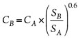
- The rule of six-tenths: Approximate costs can be obtained if the cost of a similar item of different size or capacity is known, as shown in Eq. 1:
 (1)
(1)
where:
CB=The approximate cost (USD) of equipment having size SB
CA=The known cost (USD) of equipment having corresponding size SA (same units as SB)
SB/SA=The ratio known as the size factor (dimensionless). - The cost indices: Cost indices are useful when basing the approximated cost on factors other than current prices. If the known cost of a piece of equipment is based on 1998 prices, for example, this cost must be multiplied by the ratio of the present-day index to the 1998 base index to adjust the value to present-day dollars, as shown in Eq. 2:
 (2)
(2)
where:
C=Current cost, dollars
CO=Base cost, dollars
I=Current index, dimensionless
IO=Base index, dimensionless
In this study, these methods were used to estimate the cost of the new equipment needed for each retrofit model. The estimate was performed according to the following steps:
- Use prices for existing equipment as reference prices
- Update these prices to year 2014, using the Chemical Engineering Plant Cost Index (CEPCI)
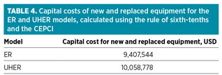
- Compare the new equipment capacities with reference capacities, and use the rule of sixth-tenths to determine their cost.
Table 4 shows the capital costs of both the ER and UHER models.
 |
The next step was to calculate the total fixed capital investment (FCI), which included other expenses required to install, construct and operate the new equipment. A number of techniques were available for estimating the FCI. These methods varied from a simple single factor to a detailed method using a code of accounts that involved item-by-item costing.
In preliminary estimates, methods were divided roughly into two categories. One group consisted of factored methods in which a series of factors were applied to items in each method, beginning with purchased or delivered equipment costs. The other group consisted of functional units or step-counting methods.
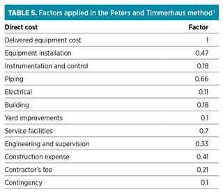
In this study, the Peters and Timmerhaus method was applied. This widely used method gives adequate estimates in the preliminary range of accuracy. Many factors are applied, beginning with the delivered equipment costs, to determine the total FCI. Table 5 summarizes these factors.
 |
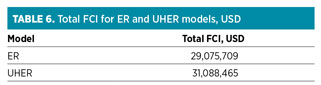
By applying these factors to the delivered equipment costs of the ER and UHER models, FCI was estimated, as shown in Table 6.
 |
Profitability analysis for retrofit models. To determine the profitability of the different retrofit models, the following steps were used:
- Determine the annual sales revenue for the existing plant
- Determine the annual sales revenue for each retrofit model
- Compare the annual sales revenue of each retrofit model with the existing plant revenue
- Determine the increase in annual revenues representing the annual net profit for each retrofit model
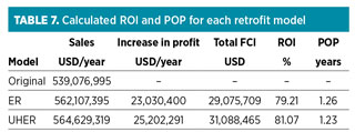
- Calculate the return on investment (ROI) and pay-out period (POP) for each retrofit model, using Eqs. 3 and 4:
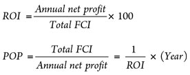 (3) (4)
Table 7 summarizes the results of applying these steps using product prices in 2014. The UHER model showed the highest ROI and lowest POP, which made it superior to the ER model.
 |
Recommendations. Commercial simulation software was used to evaluate the new proposal for retrofitting the existing LPG plant. New models were built for use in debottlenecking the existing process equipment and for rating the new process equipment needed for the retrofitted plant.
Modeling the existing LPG plant and the retrofitted plants helped to evaluate the profitability of the retrofitted plant from an economic point of view. Also, the study could be used in conceptual engineering and in contractor/licensor evaluations. GP
Acknowledgment
This research was supported by El-Wastani Petroleum Co. and its workers, engineers and managers.
Note
*The proprietary processes in this case study are Ortloff’s Gas Subcooled Process for ethane recovery (ER) and Ortloff’s Recycle Split Vapor Process for ultra-high ethane recovery (UHER). The process simulation software is AspenTech’s Aspen HYSYS technology.
Literature cited
1Couper, J. R., Process Engineering Economics, Marcel Dekker, New York, New York, 2003.
2Biegler, L. T., I. E. Grossmann and A. W. Westerberg, Systematic Methods of Chemical Process Design, Prentice Hall, Upper Saddle River, New Jersey, 1999.
3Bahnassi, E., A. Rahman Khouri, P. Alderton and J. Fleshman, “Achieving product specifications for ethane through to pentanes plus from NGL fractionation plants,” AICHE Fall Conference, Cincinnati, Ohio, 2005.
4Dimian, A. C., Integrated Design And Simulation Of Chemical Processes, Elsevier, Amsterdam, The Netherlands, 2003.
 |
Ahmed Khames El-Shatla has worked as a gas processing engineer at El-Wastani Petroleum Co. in Egypt since 2011. He has participated in the design review, commissioning and startup of several gas processing projects. Mr. El-Shatla holds a BSc degree in petroleum engineering from Suez Canal University in Egypt. He can be reached at hmed_pet_eng2010@hotmail.com.
 |
Abdelwaly Abdallah Abdelwaly is a professor of petroleum engineering at Cairo University in Egypt. He has supervised on several MSc and PhD theses, and is the author of over 60 technical papers on oil and gas. Dr. Abdelwaly holds a PhD in petroleum engineering from Cairo University in Egypt.


Comments